TiC-modified CNTs as reinforcing fillers for isotropic graphite produced from mesocarbon microbeads
2021-11-05LINXiangbaoCHENHuiWUJingWUZhigangLIRunLIUHongbo
LIN Xiang-bao,CHEN Hui,*,WU Jing,WU Zhi-gang,LI Run,LIU Hong-bo,*
(1.College of Material Science and Engineering, Hunan University, Hunan, Changsha 410082, China;2.Hunan Changyu Science and Technology Development Co., Ltd.Hunan, Changsha 410063, China)
Abstract:Multi-wall carbon nanotubes (CNTs) were modified by nano-TiC using a pressureless spark plasma sintering technology.The TiC-modified CNTs (T-CNTs) were added to mesocarbon microbeads (MCMBs) to prepare high performance isostatically pressed graphite materials.The structures of the T-CNTs and the prepared isotropic graphite materials were characterized by XRD,SEM and TEM.The mechanical and thermal properties of isotropic graphite reinforced by T-CNTs were measured by a micro-controlled electronic universal testing machine,laser thermal conductivity meter and thermal expansion coefficient meter.Results showed that the nano-TiC was successfully grown on the surface of CNTs.Compared with the isotropic graphite prepared from MCMBs without T-CNTs,the isotropic graphite with T-CNTs has a significant improvement in physical properties (density,open porosity and volume shrinkage).Its flexural strength and degree of graphitization increased by 70% and 10%,respectively,and the thermal properties were also improved to some degree.
Key words:Spark plasma sintering;TiC modified carbon nanotubes;Mesocarbon microbead;Isotropic graphite
1 Introduction
Graphite produced by isostatic pressing technology is commonly referred to isotropic graphite.Isotropic graphite has the advantages of good isotropicity,high density,high temperature resistance,thermal shock resistance,low neutron absorption cross section,and high temperature strength[1–3].It is widely used in the manufacture of semiconductors,photovoltaic materials[4],neutron regulator and structural components in high-temperature gas-cooled reactor (HTGR)[5].Generally,there are two ways to prepare isotropic graphite,the conventional method and self-sintering method[6].The graphite obtained by the conventional method is manufactured with aggregates and binders.For example,microcrystalline graphite and coke are used as aggregates,and coal-tar pitch as the binder[7].While the process of the self-sintering method is more facile,which usually utilizes carbonaceous mesophase with self-sintering properties as the raw material without any binder.In the self-sintering method,mesocarbon microbeads (MCMBs) are widely used as the raw material[8,9].The excellent capabilities of MCMBs make it become an outstanding precursor for the preparation of high performance carbon and graphite materials.
With the rapid development of science and technology,the industry has increasingly requirements for high performance isotropic graphite materials.However,the brittle character and structural defects of graphite (such as chaotic structure and pores) limit its further applications[10–13].Therefore,the preparation of isotropic graphite materials with high flexural strength and low porosity has become a means to broaden their applications.The solution for aforementioned issues includes the use of different raw materials,reduction of the particle size of the raw materials and repeatedly immersing and baking,etc[14–16].In these aspects,we have accomplished lots of work using pitch(coal tar pitch and medium temperature pitch) modified MCMBs and different particle size MCMBs[17–19].
In addition to the above,many researches with regard to modification of MCMBs have been carried out in order to produce high-property carbon and graphite materials.Cheng et al.[20]used carbon nanotubes (CNTs) as the nucleating agent to prepare CNT/MCMB composites through thermal coagulation.The maximum flexural strength of this material after carbonization reached 79.6 MPa.Shen et al.[21]mechanically mixed CNTs with MCMBs by ultrasonic agitation,the maximum flexural strength of isotropic graphite was improved by 20%.Apart from CNTs,TiC was also used as a catalyst and enhancer in the manufacture of graphite with superior mechanical properties and thermal properties[22,23].Farhad Saba et al.[24,25]added TiC-modified CNTs to the Al-matrix composite.Finally,the yield strength of the composite reached 84.36 MPa,which was 55% higher than that of pure Al (54.49 MPa).Although the performance had been greatly improved,the production process was too cumbersome.
In this work,TiC-modified carbon nanotubes (TCNTs) were prepared by novel pressureless spark plasma sintering (SPS)[24].Compared with the traditional high temperature and high vacuum process for producing TiC,the SPS method was more efficient,simpler and safer[26–28].The T-CNT/MCMB composite was obtained by uniformly mechanically mixing TCNTs with MCMBs by continuous ultrasonic agitation,followed by isostatic pressing.The aim of this work is to utilize the respective capabilities of CNTs and TiC to jointly enhance the mechanical and thermal properties of the final product.
2 Experimental
2.1 Preparation of T-CNT/MCMB composites
Raw materials used in this experiment were titanium powder (purity 99.9%,325 mesh,Aladdin),multi-walled CNTs (purity 95%,length 10–30 μm,diameter ≤ 8 nm,Nanjing Xianfeng Nanomaterials)and mesocarbon microbeads produced by Taiwan Sinosteel Carbon Chemical Co.,Ltd.The physical parameters of MCMBs are listed in Table 1.

Table 1 Physical parameters of MCMBs.
The preparation of TiC-modified CNTs could be divided into 3 steps.First,Ti powder and CNTs weremixed into hexane at a mass ratio of 4∶1 (atomic ratio 1∶1).The mixture was stirred for 1 h in an ultrasonic bath,then subjected to wet ball milling for 24 h at a rotation speed of 350 r min−1.Second,a certain amount of original CNTs ultrasonically dispersed for 60 min were added into above mixture (mass ratio:mixture∶CNTs=3∶2),ball-milled for another 1 h at 250 r min−1,and then vacuum dried for 24 h.Finally,the dried samples were sintered pressurelessly under discharge plasma for 5 min at 1 050 °C to obtain TiC-modified CNTs (T-CNTs).
Subsequently,T-CNTs were added to a certain amount of ethanol for ultrasonic dispersion for 30 min and 150 g of MCMBs was added into the ultrasonic bath and stirred for another 60 min.Finally,as-obtained mixture was vacuum dried at 70 °C for 24 h.Consequently,a series of T-CNT/MCMB composites in powder form with various T-CNT weight contents of 0,0.10%,0.25%,0.40%,0.60% and 0.75% were prepared.
2.2 Forming,carbonization and graphitization of T-CNT/MCMB composites
The green body of T-CNT/MCMB composites was shaped by cold isostatic pressing (CIP) molding with a mold of an inner space of Φ40 mm×100 mm,at a molding pressure of 200 MPa for 5 min.After that,the green body was heated to 1 000 °C for carbonization at a certain heating rate under the protection of N2.Finally,graphitization of the carbonized body was carried out under Ar atmosphere at 2 700 °C with a first heating step to 1 000 °C at a constant power of 10 kW,a follow-up heating step to 2 700 °C at a rate of 5 °C min−1,and a cooling step to room temperature naturally to produce the isotropic graphite.
2.3 Characterization of the isotropic graphite samples
The volume density and open porosity (Popen) of the isotropic graphite samples were measured by the Archimedes drainage method.X-ray diffraction(XRD) patterns of the samples were recorded using a MiniFlex diffractometer with CuKαradiation.The element composition of T-CNTs was analyzed by Xray photoelectron spectroscopy(XPS).XPS measurement was performed on a Thermo Scientific ESCALAB 250Xi using AlKα as the excitation light source.Thermogravimetric analysis (TG) was also carried out in air condition with a heating rate of 20 °C min−1in the temperature range of 30-1 000 °C for the pristine CNTs and T-CNTs.The flexural strength of graphitized samples with different T-CNT contents was tested by a three-point bending method using a CTM-2500 universal material testing machine (the specification was 5×10×50 mm3,and the loading rate and span were 1 mm min−1and 40 mm,respectively).The microscopic morphology of the samples were observed by transmission electron microscopy (TEM,JEM-3010) and scanning electron microscopy (SEM,FEI Quanta 200).
The thermal diffusion rate and thermal conductivity of graphitized T-CNT/MCMB samples were measured by a LFA467 laser thermal conductivity meter (the graphitized samples were machined into 5×5×25 mm3in two different directions of axial and radial directions).The thermal expansion coefficient was measured by a STA449C thermal expansion instrument,the temperature range was 20–500 °C,the heating rate was 5 °C min−1.The coefficients of thermal expansion in two different directions were calculated.
3 Results and discussion
3.1 Structural analysis of T-CNTs
Fig.1 compares the XRD profiles of CNTs and T-CNTs.As it can be seen,the pattern of CNTs has a broad (002) characteristic diffraction peak.However,the existence of crystalline TiC is confirmed by the sharp peaks located at 36.03°,41.86°,60.70°,72.66°and 76.44° corresponding to the (111),(200),(220),(311) and (222) crystal planes of TiC[29],respectively.This shows that Ti reacts with carbon to form TiC when Ti is used to modify CNTs.It is worth noting that the peak intensity of (002) plane of T-CNTs is weakened apparently,which is due to the decreasing orderliness of carbon ascribed to the reaction of Ti with CNTs.The diffraction peak at 45° corresponds to the (100) crystal plane of CNTs.The peak intensity of(100) crystal plane is greatly affected by sintering temperature and the mixing ratio of Ti/CNTs.Generally,as the content of Ti and the sintering temperature increase,the peak gradually becomes weak until it disappears[26].The element composition analysis results of T-CNTs are listed in Table 2.
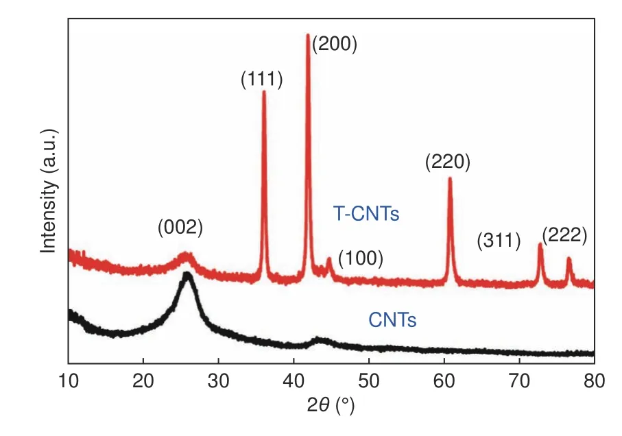
Fig.1 XRD patterns of CNTs and T-CNTs.

Table 2 Element composition of T-CNTs.
The TEM images of T-CNTs are shown in Fig.2.It can be found from Fig.2(a) that the TiC particles have been successfully grown on CNTs.In addition,the TiC nanoparticles are scattered on the tube walls of CNTs with a size of 10-30 nm .The darker regions located in the images are TiC nanocrystals (nanoblocks or nanolayers),which could be demonstrated by the EDS pattern.Simultaneously,the structural characteristics of CNTs maintains well after pressureless SPS.The TiC nano blocks and layers have different formation mechanisms[24].One way is that the crushed carbon from ball-milling treatment and Ti sources (clusters/atoms) are deposited on the defect sites on the surfaces of CNTs through shallow-diffused/attached effect,following the in-situ formation of TiC nanolumps after pressureless SPS sintering,as shown in Fig.2(b).Another way is that the deep-diffused Ti atoms directly spread onto or into the walls of CNTs by various thickness to generate the TiC nanolayers.Six-member rings of graphene in CNTs in some areas are slightly destroyed in some areas during ball milling to create defects,which are larger than the size of the Ti atom (the atomic radius of Ti is 0.145 nm).Ti atoms are abnormally active at high tempereture and thereby could diffuse directly into the interlayer space of CNTs (interlayer spacing 0.34 nm[30]) through defects during sintering.The formation of such TiC nanolayers between CNT walls could be witnessed from Fig.2(c).The diameter of TCNTs gets significantly larger (greater than 8 nm) compared with CNTs,indicating the presence of TiC nanolayers in this region.

Fig.2 TEM images of T-CNTs.(a) Local morphology of T-CNTs.(b) Partial enlargement of TiC nanoblocks on T-CNTs.(c) Partial enlargement of TiC nanolayers on T-CNTs.The illustrations in (b) and (c) are the EDS spectra at the region illustrated by the red arrows.
From the TG curves shown in Fig.3,it can be seen that there is distinct difference in thermal properties between pristine CNTs and TiC-modified CNTs.The weight loss of pristine CNTs starts off around 480 °C,and the loss rate rises obviously in the temperature range of 540–620 °C with a weight loss of nearly 99% in the end.The maximum weight loss temperature of T-CNTs is around 640 °C,and the weight loss is 30.76%.The weight loss temperature of T-CNTs is improved by about 100 °C,which implies that nano-TiC formed on the surface of CNTs after sintering could protect CNTs from oxygen,leading to an increase of the oxidation temperatures of T-CNTs.The TG curve of T-CNTs shows an increase in mass around 400 °C,which is due to the oxidation of the TiC layer (TiC and O2react to form Ti3O5at 380 °C,Ti3O5eventually reacts to generate TiO2with the elevation of temperature[31]).
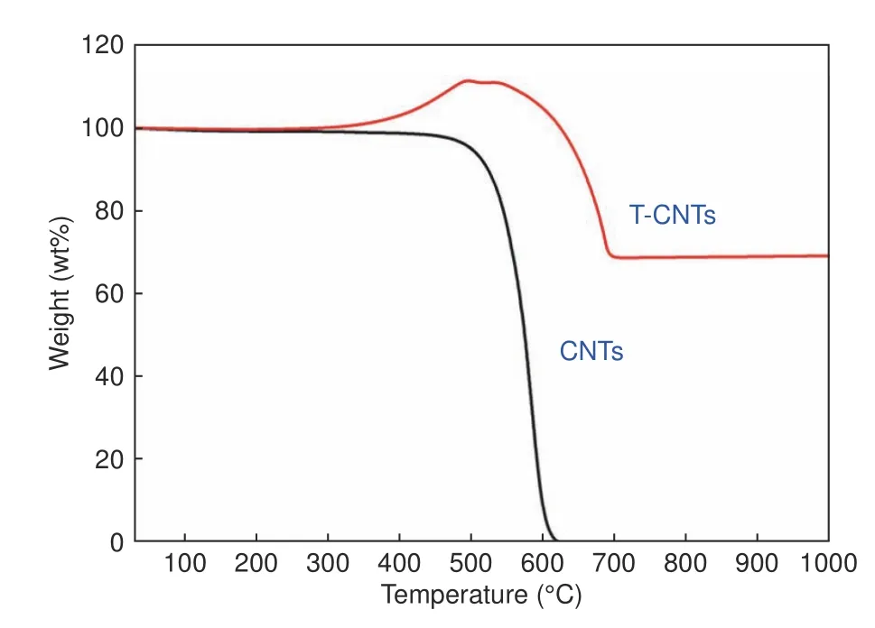
Fig.3 TG curves of CNTs and T-CNTs in air.
3.2 Mechanical and thermal properties of isotropic graphite
The various performance curves of MCMBs with different T-CNT contents are shown in Fig.4.From Fig.4(a),as the content of T-CNTs increases,the bulk density and volume shrinkage of the composites exhibit maxima.The bulk density reaches the maximum of 1.848 g cm−3at 0.40 wt% T-CNTs.However,the bulk density of the samples decreases rapidly when the T-CNTs content exceeds 0.40 wt%,which is due to the fact that the content of T-CNTs is too high and ultrasonic stirring is not sufficient to uniformly disperse them in MCMBs,leading to local agglomeration of T-CNTs.A similar situation is also reflected in Deng's work[32].The volume shrinkage has a similar trend to the bulk density (the blue line in Fig.4 (a)).When the content of T-CNTs increases,the volume shrinkage increases from 32.86% to 36.37%,then decreases beyond 0.40%.Fig.4(b) shows the open porosity of T-CNT/MCMB composites,which reduces from the initial 14.56% to 8.48% with increasing the T-CNT content,indicating a significant reduction in the number of internal holes (openings and vias).A reasonable explanation is that an appropriate amount of T-CNTs promotes the sintering of MCMBs,thereby increasing the bulk density and decreasing the number of pores.Obviously,these are beneficial to the improvement of product performance.
The flexural strength of the graphitized samples is shown in Fig.4(c).The graphite samples prepared by pure MCMBs (without ethanol treated) has a flexural strength of 14.29 MPa.The composites with TCNTs exhibit significantly improved flexural strength.The T-CNT/MCMB graphite with a T-CNT content of 0.40 wt% reaches a maximum bending strength of 24.58 MPa,which is increased by 72%.Subsequently,as the content of T-CNT further goes up,the flexural strength begins to gradually descend.Nevertheless,compared with the reported work of the CNT enhanced MCMB composites[21],T-CNT/MCMB composites exibit superior enhancement.The stress-strain curves of pure MCMB graphite simple and TCNT/MCMB graphite simples with various contents of T-CNTs are shown in Fig.4(d).All samples exhibit the linear elastic behavior,and the flexural modulus could be calculated by the slope of the curve.After adding T-CNTs,the elongation at break and the fracture strength of isotropic graphites are greatly increased.
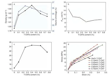
Fig.4 Effect of the T-CNT content on the properties of composites;(a) The bulk density and volume shrinkage curves;(b) The open porosity of the composites;(c) The flexural strength of composites and (d) The stress-strain curves of composites.
The work of mechanically mixed pristine CNTs and MCMBs to manufacture isotropic graphite has also been completed.The combination properties of isotropic graphite samples are listed in Table 3.From the comparison,we could find that although the addition of CNTs improves the performance of the samples,the introduce of TiC further improves the performance of isotropic graphite simples.The results indicate that T-CNTs are more conducive to sintering of isotropic graphite than CNTs.

Table 3 The combination properties of different samples.
Fig.5 demonstrates the effect of the content of TCNTs on the thermal properties of graphite samples.The thermal conductivity (λ) and thermal diffusivity(α) of the samples can be calculated by the formula as follows:
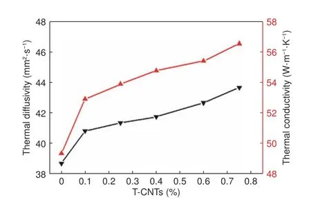
Fig.5 Effect of the T-CNT content on thermal diffusivity and thermal conductivity of composites.

Whereρis the sample density and c is the specific heat capacity of the samples.As it can be seen from Fig.5,with increasing the T-CNT content,the thermal diffusivity and thermal conductivity increase from from 38.699 to 43.672 mm2·s−1and from 49.347 to 56.550 W·m−1K−1,respectively.It could be deduced that,the thermal conductivity of the isotropic graphite material is improved with the help of TiC and CNTs.On one hand,the thermal conductivity of CNTs is quite high (>3 000 W m−1K−1)[33].On the other hand,the thermal conductivity of carbon graphite material increases exponentially with the enhancement of graphitization degree[34].When the thermal conductivity is increased,the temperature gradient and thermal stress in the sample could be significantly decreased during heating.This will facilitate its omnifarious role in thermodynamics.
The coefficient of thermal expansion (CTE) values and the CTE-based isotropy ratios of the isotropic graphite samples are listed in Table 4.The graphite samples have an isotropic microstructure with the random orientation of spherical particles.The isotropy ratio of pure MCMB isotropic graphite is 1.07.After the addition of T-CNTs,the isotropic ratio of samples is as low as 1.02.In another words,T-CNTs does not have an adverse impact on the isotropic structure.The CTE values of T-CNT/MCMB are low due to the change of thermal diffusivity and thermal conductivity.As it is well known that the higher the thermalconductivity of the sample is,the more uniform the temperature in all parts of the sample is.

Table 4 CTE and isotropic ratios of graphite samples with different T-CNTs contents.
3.3 Structural analysis of isotropic graphite after graphitization
Fig.6 shows the XRD patterns of different CNT/MCMB graphite samples after graphitization.Fig.7 shows the XRD patterns of the graphitized samples with different T-CNT contents.Obviously,the sharp and strong peak located at 25.6° corresponds to the (002) plane of graphite,the (100) diffraction peak is clearly separated from the (101) diffraction peak,and the (004) and (110) diffraction peaks could also be observed.These indicate that all samples have a high degree of graphitization.The characteristic peaks of TiC are too weak to be detected due to its relatively low content.However,from the local enlarged XRD patterns of Fig.7,the (111)and (220) diffraction peaks of TiC begin to emerge when the T-CNT content exceeds 0.25%,and the intensity of the diffraction peaks becomes strong with increasing the T-CNT content.This evidence supports that TiC also retains in the graphite matrix.The graphitization degree of CNT/MCMB and T-CNT/MCMB graphite samples are listed in Table 5 and Table 6,respectively.With the increase of the CNT content,the graphitization degree of CNT/MCMB composites exhibits a maximum of 70.9%.After TCNTs are added,the graphitization degree increases sharply from 64% to 75.6%,which increases slightly with the T-CNT content,which is attributed to the effect of catalytic graphitization of TiC[35].
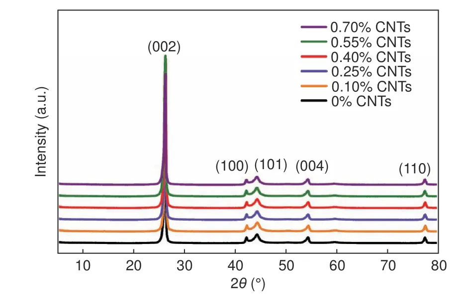
Fig.6 XRD patterns of different CNT/MCMB graphite samples after graphitization.

Fig.7 (a) XRD patterns of different T-CNT/MCMB graphite samples after graphitization and (b) the partial enlarged view of XRD patterns.

Table 5 Degree of graphitization of CNT/MCMB graphite samples calculated by XRD results.

Table 6 Degree of graphitization of T-CNT/MCMB graphite samples calculated by XRD results.
The strengthening mechanism of T-CNTs is analyzed by the fracture morphology of graphitized TCNT/MCMB samples,as depicted in Fig.8.It can be observed that the sections could be divided into three types:(i) voids formed as the results of the breakage of samples and the shrinkage of particles during sintering (Fig.8(c)),(ii) interparticle breakage produced a rough and convex morphology produced by interparticle breakage and (iii) a smooth cleavage plane generated by innerparticle breakage,as shown in Fig.8(d).If the interfacial strength between the particles is stronger than the particle strength,the particles will break,and a large number of cleavage faces are generated (innergranular fracture occurs instead of the intergranular mode).The cleavage happens between (002) planes,on account of the weak van der Waals force between graphite layers[21].The higher the interfacial strength is,the better the mechanical properties of the sample are.Therefore,if a large number of cleavage planes are observed in the cross-sectional morphology of samples,the mechanical strength and the binding force between the particles will be confirmed to be stronger.Comparing Fig.8(a)and (b),it is found that the sample of pure MCMBs has hardly any cleavage planes in the cross section.The entire particle is even completely detached,as shown in Fig.8(c),indicating that the adhesion and interface strength between the particles of the sample prepared by pure MCMBs is extremely weak and inferior.Conversely,many smooth cleavage planes are observed after 0.40% T-CNTs are added into the sample of MCMBs (Fig.8(b)).Thus,greater interface strength is obtained with the addition of T-CNTs,which is also considered to have higher mechanical strength.
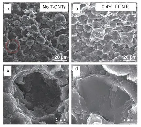
Fig.8 SEM images of the composite cross section.(a) Sectional morphology of MCMB sample.(b) Cross-sectional morphology of samples with 0.40% T-CNTs added.(c) Holes formed by the detachment of particles when they are broken (the dotted line in a) and (d) Smooth cleavage surface.
For T-CNT/MCMB composites,the particle interface of the MCMBs exhibits better mechanical behavior because of the addition of T-CNTs.With the effect of ultrasonic agitation,T-CNTs are uniformly dispersed on the surface of MCMBs.For T-CNTs,CNTs have a good chemical compatibility with MCMBs and TiC and CNTs synergistically promote sintering,making the particles more compact and stronger.From Fig.9(a) and (b),it can be clearly seen that the tails of the T-CNTs are sintered integrally with the surface of the MCMBs without a clear boundary.The distinct rough and smooth portions seen on the left and right sides of T-CNTs demonstrate that adding T-CNTs prevents interparticle breakage when subjected to external forces.The presence of nano-TiC in this region could be confirmed from Fig.9(d).The presence of silky T-CNTs on the surface of cleavable MCMB particle in the region 1 of Fig.9(e) could be clearly observed,which also proves that the separation between MCMB particles is effectively hindered,resulting in the cleavage of the MCMB particles.Regions 2 shows that the fracture of the particles is not due to the existence of microcracks in the particles (Fig.9(f)),but that the T-CNTs give rise to a cleavage of innerparticle resulted from the higher interfacial strength than the particle strength.

Fig.9 SEM images of the interface with T-CNTs.(a) SEM image of T-CNTs to prevent interparticle breaks.(b) A partial enlarged view of Fig.a;(c,d) EDS mapping in the dotted line in Fig.b.(e) Particles in the fracture.(f) The area labeled 2 in Fig.e is partially enlarged.
4 Conclusion
T-CNTs as the reinforcing filler of isotropic graphite were successfully prepared by the pressureless SPS method.The synergistic effect between CNTs and TiC causes a significant change in the structure and properties of isotropic graphite.In the process of carbonization and graphitization,the presence of T-CNTs promotes bonding between MCMB particles and enhances the interfacial strength.As a result,the breakage of interparticles is effectively suppressed.After graphitization,with the increase of the T-CNT content,the tensile strength of samples is elevated and the maximum increment is 70%,the degree of graphitization is increased by 10%,and the thermal conductivity is also improved.And that,when T-CNTs is added with a content of 0.40%,the overall performance of the material is the best.
Acknowledgements
The authors gratefully acknowledge the financial support for this work provided by National key research and development plan (2017YF0310905),the Natural Science Foundation of China (51402101) and Hunan Provincial key research and development plan(2018GK4012,2018GK1030).
杂志排行
新型炭材料的其它文章
- Properties and microstructures of a matrix graphite for fuel elements of pebble-bed reactors after high temperature purification at different temperatures
- Microstructure of high thermal conductivity mesophase pitch-based carbon fibers
- 高导热聚酰亚胺石墨膜/环氧树脂复合材料的制备与性能表征
- One-pot modified“grafting-welding”preparation of graphene/polyimide carbon films for superior thermal management
- Thermal conductivity of graphite nanofibers electrospun from graphene oxide-doped polyimide
- A mini review:application of graphene paper in thermal interface materials
