The far-field plasma characteristics of LHT40 low-power Hall thruster for commercial aerospace applications
2021-10-31XinweiCHEN陈新伟ZuoGU顾左JunGAO高俊
Xinwei CHEN (陈新伟), Zuo GU (顾左), Jun GAO (高俊),
Shangmin WANG (王尚民), Tao CHEN (陈焘), Ning GUO (郭宁),Sanxiang YANG (杨三祥) and Chao LIU (刘超)
Science and Technology on Vacuum Technology and Physics Laboratory, Lanzhou Institute of Physics,Lanzhou 730000, People’s Republic of China
Abstract To achieve a better insight into the far-field plasma spatial distribution and evolution characteristics of the 300 W class low-power Hall thruster (LHT) for commercial aerospace applications, a dedicated and integrated plasma diagnostic system composed of seventeen Faraday cups (FC)and two triple Langmuir probes (TLP)is established to investigate the timeaveraged in situ spatial distribution characteristics of far-field ions and electrons.The ion current density (ICD), plasma potential, plasma density, and electron temperature at 1000 mm downstream of 300 W class LHT for commercial aerospace applications in the azimuthal angle range of −90° to 90° were investigated under the conditions of different anode mass flow rates and discharge voltages.The results demonstrated that ICD, beam divergence angle, and mass utilization efficiency increased with increasing anode mass rate.The double-wings phenomenon was observed in the spatial distribution of ICD at large angles from the thruster axis, which is attributed to charge exchange collisions at increasing vacuum backpressure.The plasma electron temperature, electron density, and plasma potential parameters derived from the TLP decreased rapidly in the angle range from 0° to 30° and did not exhibit significant variations above 30°,which was also in good agreement with the results of the measured divergence angle of the FC.The discrepancy of average ion speed was calculated.The maximum error is better than 31.5%which checks the consistency between the TLP’s results and that of FC to some extent.
Keywords: low power Hall thruster, plasma characteristics, commercial aerospace, plasma diagnostic system
1.Introduction
It is generally known that electric propulsion has the advantages of high specific impulse compared with chemical propulsion, which can significantly save the mass of propellant and reduce the launch cost [1].Among several electric propulsion systems, Hall thrusters (HT) have many advantages such as simple structure, low thrust, high specific impulse,long life, high integration, and the high thrust-to-power ratio[2,3],which have realized a wide range of space applications and are mainly used for various orbital missions such as attitude control, orbital hoisting, and deep space exploration.In recent years, compared to large communication satellite platforms that have achieved in-orbit applications using a variety of HT in the 1–5 kW power range [4, 5], the microsatellites [6] have drawn significant attention from satellite manufacturers because of their wide range of applications and high economic profitability, and have made rapid developments.With speeding up the emergence of low earth orbit(LEO) Internet constellations and the demand for orbital high-precision maneuvers, the well-known commercial space companies represented by OneWeb [7] and SpaceX [8] have vigorously developed LEO Internet constellations with lowpower Hall thruster (LHT) as propulsion systems for highprecision station keeping and orbit insertion.Attracted by the enormous demand for propulsion systems in commercial aerospace, the 300 W class LHT with an outer diameter of 40 mm (LHT40) was specifically developed by the Lanzhou Institute of Physics (LIP).
Nevertheless, LHT [9, 10], whose primary performance parameters, such as specific impulse, efficiency, and thrust,depend significantly on the structure of the beam plasma,has large surface-to-volume ratios resulting in poorer performance of LHT than medium and high-power HT.Therefore, the correlation between the plume characteristics and the dimensions of the LHT is highly essential to improve the scaling relationship of the LHT and is of great value for the successful integration of thrusters and spacecraft on-orbit and plume shielding.The plume generated by the electric thruster causes interaction between the spacecraft and the surrounding environment, reducing the performance of the spacecraft subsystems and on-board sensors.The plume containing energetic particles, electrons, neutral atoms, etc will have a variety of adverse effects on the spacecraft: (1) space charge effects result in a charged spacecraft surface; (2) various charged particles change the electrical and thermal properties of the spacecraft surface;(3)plume deposition will contribute to the performance degradation of solar cell panel, thermal control surfaces,and optical windows,etc.Many studies have been conducted in identifying the performance and efficiency of LHT [11–14] with Faraday probe [15–17] and cylindrical Langmuir probe [18–20] which are commonly used to perform medium and high-power HT beam plasma studies.But,a single Faraday probe [15–17] combined with a moving mechanism was employed in previous studies, which cannot determine the simultaneous spatial distribution characteristics of beam plasma.In addition, there are rarely studies on the far-field plasma spatial distribution and evolution characteristics of LHT.The plume plasma characteristics of LHT are an external manifestation of LHT.The plume characteristics of LHT are of great interest to study because of their large surface area to volume ratio.Reconstructing the spatial plasma parameter distribution is of great value for understanding the operating mechanism of LHT.
In this work, a dedicated and integrated plasma diagnostic system (PDS) composed of seventeen Faraday cups(FC) and two triple Langmuir probes (TLP) is established to investigate the time-averagedin situspatial distribution characteristics of far-field ions and electrons of the 300 W class LHT for commercial aerospace applications.The ion current density (ICD), plasma potential (Vsp), plasma density(Ne), and electron temperature (Te) at 1000 mm downstream of LHT in the azimuthal angle range of −90° to 90° were investigated under the conditions of different anode mass flow rates and discharge voltages.
2.Experimental set-up
2.1.LHT40 HT
The LHT40-V1, composed of an anode, discharge chamber,magnetic circuit, and a hollow cathode, etc, is the primary version of the 300 W class LHT developed independently by the LIP, which is a type of stationary state plasma thruster.The picture of the LHT40-V1 HT is shown in figure 1.
The discharge chamber consists of a BN-SiO2annular discharge channel with an external diameter of 40 mm and a width of 10 mm.The propellant gas is uniformly injected inside the channel through the gas distributor and the anode,which consists of a non-magnetic stainless steel ring placed at the bottom of the discharge channel and adjacent to the outer ceramic wall.The magnetic field is generated by electromagnetic coil components(four outer coils, one internal coil,one internal trim coil, and magnetic screen, etc).The magnetic field lines of LHT40-V1 are concave and symmetric about the discharge chamber centerline, which is similar to the NASA-173Mv1 HT[21].Furthermore, the peak of radial magnetic field magnitude of the channel middle diameter(Br)located at the exit of the thruster discharge channel is approximately 140 G and the distribution of magnetic field magnitude at its channel middle diameter shows a positive gradient, as shown in figure 2.The cathode is a 3 A emitting current LaB6hollow hot cathode, located outside the four excitation coils.The typical operating parameters of LHT40-V1 HT are shown in table 1.
2.2.Plasma diagnostic system (PDS)
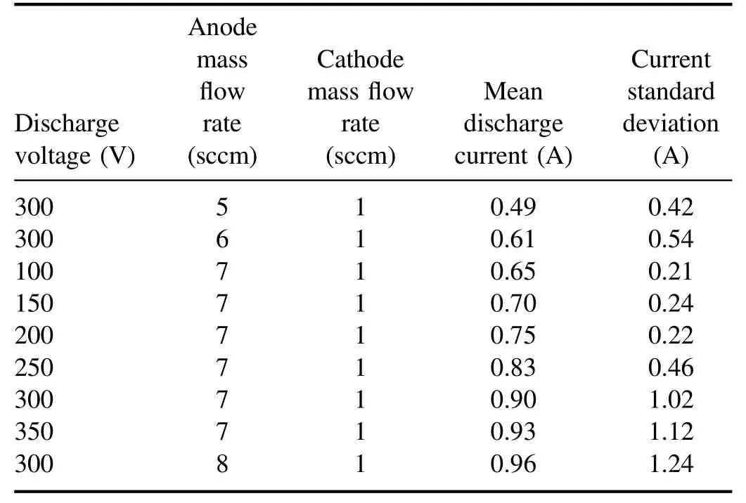
Table 1.Typical operation parameters of LHT40-V1 Hall thruster.
The dedicated and integrated PDS [22] consists of seventeen FC,two TLP,a rotary rake,an integrated control system,and an advanced post-processing system used to perform investigation of ICD,plasma potential,plasma density,and electron temperature.The rotary rake controlled by the motor is rotated around thez-axis defined by the thruster exit plane(the thruster coordinates are defined as shown in figure 3),and its rotation radius is 1000 mm.The rotation angle range(θ)of the rake is ±90° with rotation precision ±0.1°.The FC is distributed at 0°, ±10°, ±15°, ±20°, ±25°, ±35°, ±45°,±60°, ±75° positions of the rake, as shown by the yellow arrows in figure 3(b) and two TLP are symmetrically distributed at the 0° axis of the rake on both sides, which are at an angle of 10 with theY-axis of the thruster exit plane.The experiment was conducted in the vacuum system (chamber TS-6C) of LIP, which consists of a vacuum chamber with a diameter of 4.2 m and a length of 10 m and equipped with six external cryogenic pumps(1×10⁴l s−1for nitrogen)and 20 internal cryogenic pumps (1.49×10⁴l s−1for xenon gas).The no-load ultimate vacuum pressure of the vacuum system is better than 5.0×10⁻⁵Pa, and the operating pressure is better than 1×10⁻³Pa at a xenon mass flow rate of 8 sccm.One KF-40 ion gauge , which is parallel to the thruster exit plane, is mounted on the vacuum wall.The schematic of the vacuum facility and measuring apparatus is shown in figure 3(a).The relative positions of the PDS and thruster in the vacuum chamber are shown in figure 3(b).
2.2.1.Faraday cups.The FC is composed of a collector,gathering the ions coming from the plasma source,a polarized shield, acting as a filter for the electrons, and an ammeter measuring the current from the probe collector to the vacuum chamber ground,as shown in figure 4.The main output of an array of FC is the ICD distribution(ICAD).The FC collector and external shield (EXT SHLD) are set to −40 V.The collection area of a FC is 100 mm2.The FC can be utilized to obtain the total beam ion current(Ii,tot).Whenr>10d(rand
drepresent the distance between the entrance hole of the probe and the exit plane of the thruster,and outer diameter of the thruster exit cross-section), the plasma plume can be considered to originate from the center of the thruster exit plane (a point source) [23].The total ion current [24, 25] is therefore equal to the integral over the ICDjihemisphere,i.e.

whereR, θ, andjidenote the distance of the probe collection surface from the center of the thruster exit cross-section, the angle between the central axis of the collection surface of the probe, and the ICD is collected by the probe, respectively.Ii,totwas calculated by the central FC (at 0°) during the rake rotation in the range of ±90° in this paper.
In this case, the plume divergence half-angle (PDHA,θdiv) is defined as the plume boundary containing 90% of the total ion current (Ii,90%) [25, 26], as shown in equation (2)

2.2.2.Triple Langmuir probe.The TLP used here, derived from Chen and Sekiguchi’s design [27], consists of three cylindrical tungsten wires (P1, P2, P3) with a diameter of 4 mm and a length of 57 mm.The distance between each two of the three tips is 8 mm.The TLP placed in the plasma bulk consists of three voltage-biased electrodes and allows the evaluation of plasma characteristic parameters such as plasma potential (Vsp), plasma density (Ne), and electron temperature(Te).The picture and principle scheme of TLP is shown in figure 5.The TLP, composed of two bias electrodes (P1, P3)to which a fixed voltage of 32 V is applied and an additional third electrode (as a floating electrode), has the advantage of instantaneous availability of plasma parameters without a complex scanning circuit comparable to that of single Langmuir probe.The TLP is widely used in plasma diagnostics for pulsed plasma thrusters, HT, ion thrusters,and other thrusters.Plasma potential (Vsp), plasma density(Ne), and electron temperature (Te) are derived by a specially developed post-processing program.
The electron temperature (Te) and electron number density (Ne) can be represented as equations (3) and (4)[22], respectively

HereV21andIrepresent the voltage between probe electrodes P1 and P2 and the current between electrodes P1 and P3,respectively.Thek,e,S, andmirepresent the Boltzmann constant,the single electron charge,the ion collection area of the probe, and the mass of the xenon atom, respectively.
The plasma potential (Vsp) can be written as the below[22]:

whereV21represents the potential difference between probe electrodes P1 and P2,−V1refis the acquired voltage between probe electrode P1 and the external reference, respectively.
3.Results and discussion
The estimation of the plasma parameters within the far-field plume of the 300 W LHT (LHT40-V1) is displayed for diverse working conditions.The ICD (Ii), beam divergence angle (θ), mass utilization efficiency (ηm), plasma potential(Vsp),plasma density(Ne),and electron temperature(Te)were investigated under various discharge voltages (100–350 V)and anode mass rates(5–8 sccm).The xenon propellant with a purity of 99.9995% was delivered to the anode and cathode through a dedicated mass flow controller with an accuracy of 1% of full scale (10 sccm).For each operating condition, the discharge current oscillation was recorded.Comparing the discharge current and discharge current oscillations with different probe positions in the plume, it was observed that there was no influence of the discharge behavior regardless of the probe positions.Before the beam plasma diagnosis, the thruster was carried out for a continuous discharge period up to 2 h.The thruster was essentially considered to reach thermal stability,due to the discharge current remaining constant.During the plume test, the entire period of each operating condition (θ from −90° to +90°) was about 5 min.
3.1.FC measurement results
3.1.1.Influence of the anode mass flow rate.The influence of the anode mass flow rate on the plasma parameters of the far-field plume was investigated at a fixed anode voltage of 300 V (Ud=300 V), a cathode mass flow rate of 1 sccm(mc.=1 sccm),and an excited current of 3.2 A(Iec=3.2 A).The range of the rotary rake is ±90° and the angular resolution of the data collected during the rake rotation is 3°.The ICD distribution of the thruster is obtained by the discrete ICDs of the probes at different locations using a linear differential smoothing algorithm.Figure 6 shows the spatial distribution profile of the ICD with anode flow rate(ma.)from 5 to 8 sccm(interval 1 sccm)discharge voltage for a cathode mass flow rate of 1 sccm and a discharge voltage of 300 V.In figure 6, the probe position represents the specific physical distribution and the angle represents the rotation angle in respect to theZ-axis (as shown in figure 3).
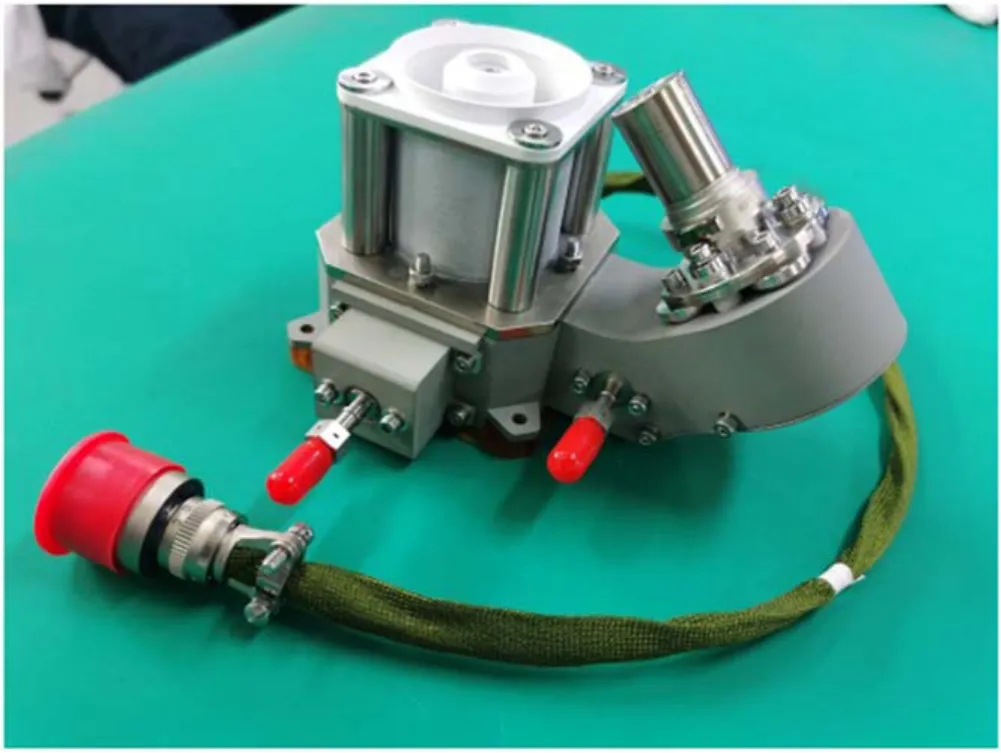
Figure 1.The picture of the LHT40-V1 Hall thruster.
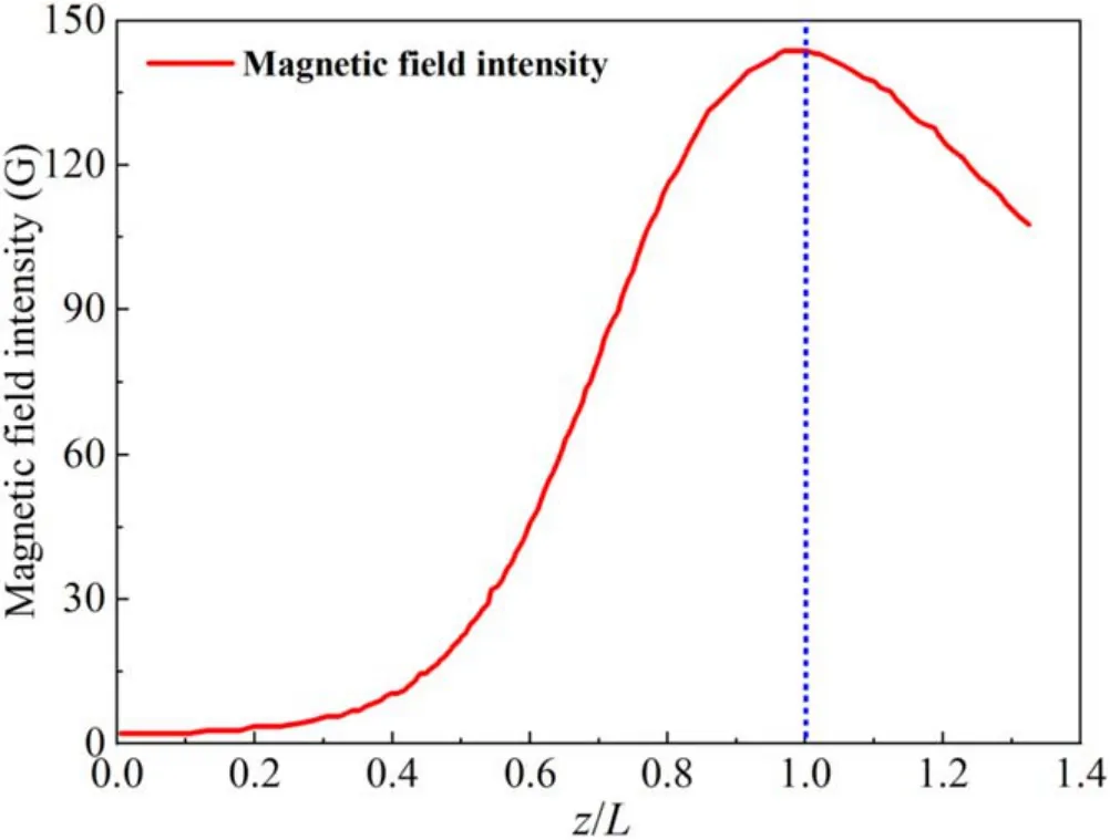
Figure 2.The distribution of magnetic field strength at the channel middle diameter of the LHT40-V1 Hall thruster (L represents the channel length,and z represents the distance from the anode surface,z/L is a dimensionless number).
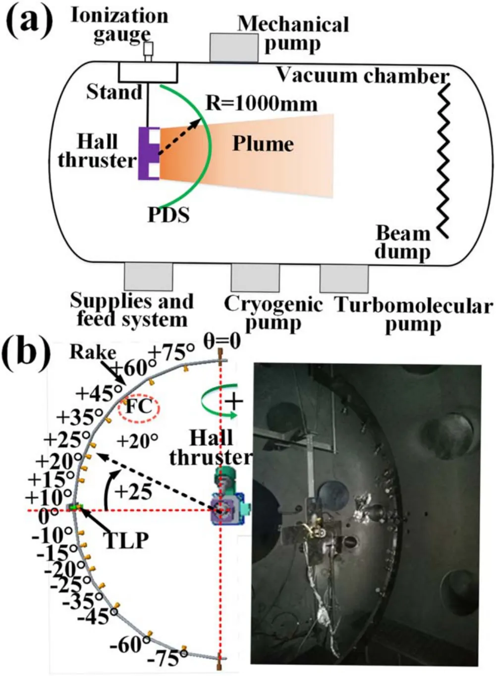
Figure 3.Schematic of the vacuum facility and measuring apparatus(a), the relative positions of the PDS and thruster in the vacuum chamber (b).
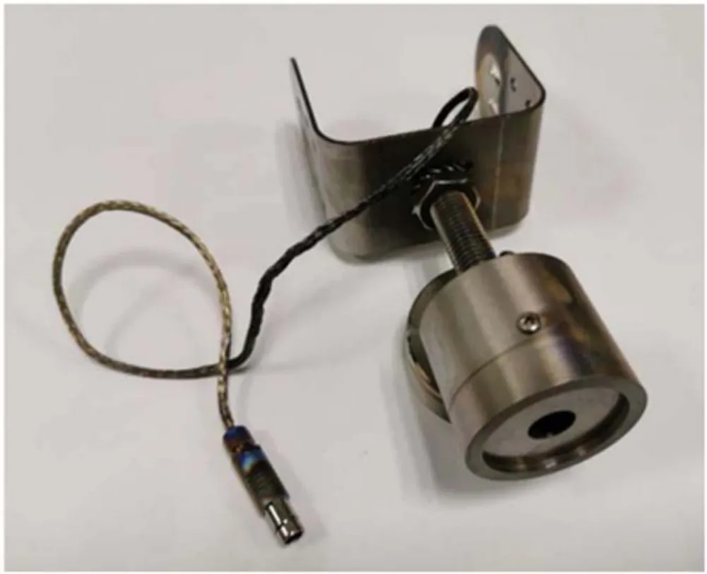
Figure 4.The picture of FC.
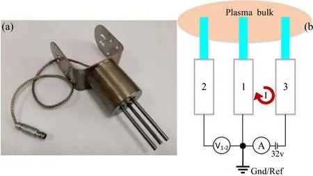
Figure 5.The picture (a) and principle scheme (b) of TLP.
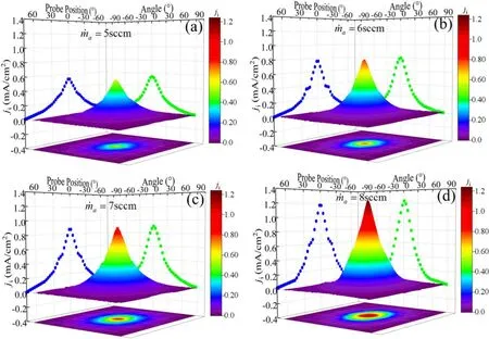
Figure 6.The distributions of ICD with different anode mass flow rates under cathode mass flow rate of 1 sccm and discharge voltage of 300 V.
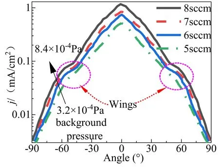
Figure 7.The distributions of ICD with different background pressures.
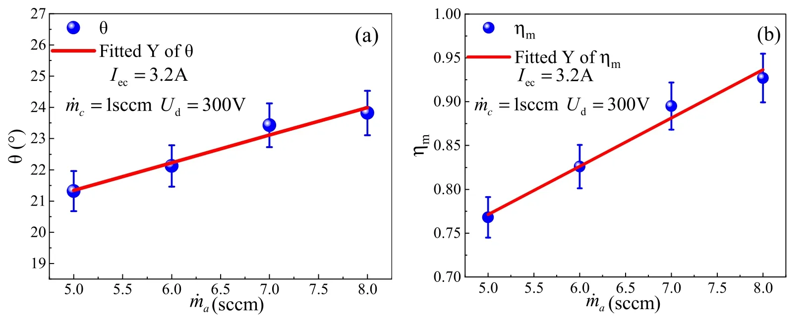
Figure 8.The profiles of beam divergence angle (a) and mass utilization efficiency (b) with anode mass flow rates under the cathode mass flow rate of 1 sccm and discharge voltage of 300 V.

Figure 9.The distribution of ion current density with discharge voltage under cathode mass flow rate of 1 sccm and anode mass flow rate of 7 sccm.
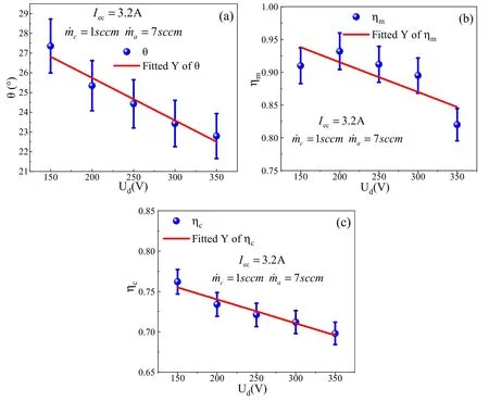
Figure 10.The profile of beam divergence angle (a), mass utilization efficiency (b), and current utilization efficiency (c) with different discharge voltages under cathode mass flow rate of 1 sccm and anode mass flow rate of 7 sccm.
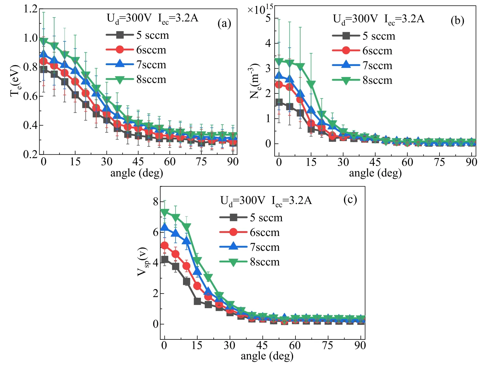
Figure 11.The profiles of electron temperature (a), plasma density (b), and plasma potential (c) with different anode mass flow rates at different angles.
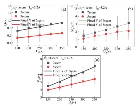
Figure 12.The profiles of electron temperature (a),plasma density(b),and plasma potential(c)at different discharge voltages with TLP 0°position.
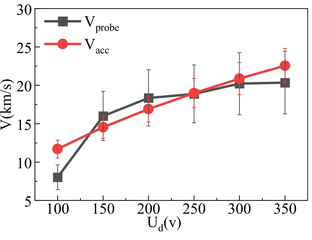
Figure 13.The curves of average ions velocity with the different discharge voltages.
As can be seen from figure 6, the ICD is symmetrically distributed with the center of the thruster.The maximum value of ICD is located at the thruster axis.The ICD decreases sharply off-axis (e.g.the ICD is 0.78 mA cm−2when FC is located atφθ= =0,0 in figure 6(b).However, the ICD decreases to 0.28 mA cm−2when the angle increases to 42°).As the anode mass flow rate increases from 5 to 8 sccm, the ICD increases from 0.54 to 1.26 mA cm−2, an approximate percentage increase of 133.3%.The main reason for the analysis may be that with the increasing density of neutral atoms in the HT discharge channel, the probability of collision of electrons and atoms increases.To some extent,the more frequent the probability of collisions between electrons and atoms, the higher the number of ions in the plume.The ICD increases with increasing anode mass flow rate under other constant conditions.
Besides,the wings were observed at approximately±60°for each operating condition and this structure has been identified as a result of the backpressure effect [23] and the shape of this ion current is similar to other medium and high power HT plume profiles [28–30].The distribution of ICD with different background pressure is shown in figure 7.As the anode mass flow rate increases, the back pressure gradually increases and the ‘wings’ phenomenon becomes more and more obvious.It was also noticed that the ICD distribution profile widens with increasing anode mass flow rate.This phenomenon has been observed in plume measurements of the multiple HT, e.g.SPT-100 [28],PPS1350-G [29], and BHT-600 [30].The problem [23] was attributed to the charge exchange (CEX) collisions as a consequence of the increase of the vacuum chamber background pressure as the anode mass flow rate increases for a certain pumping speed.The CEX collision is the result of a fast-moving xenon ion () colliding slow-moving neutral atoms (xeslow), giving a fast atom (xefast) and a slow ion ().In the HT plume, the large curvature of the magnetic field lines[21]leads to thegradual increase in the off-axis region of the radial electric field gradient, which further contributes tobeing accelerated to large angular positions.So, background pressure is an essential consideration in measuring ICD.As the anode mass flow rate increases,the probability of CEX occurring is greater.Therefore, the total ion current is overvalued as the background pressure rises,leading to an overvaluation of the thruster performance.
The mass utilization efficiency (ηm) is an important parameter to evaluate the design of HT and represents the percentage of neutral atoms converted to ions, which is expressed in equation (6) [23, 25].

wherem.i,Iiandm.adenote the mass flow rate of ions in the beam,ion current(considering only single charged ions),and atom mass, respectively.
As can be seen from figure 6,the ICAD is approximately symmetrical with the center of the thruster.TheIi,totwas calculated by the central FC (φ= 0) during the rake rotation in the range of ±90° in this paper.Besides, the total ion current (Ii,tot-2) was also derived from the ICD measured by the remaining FC.The difference betweenIi,totandIi,tot-2was less than 1%.Given that the ‘wings’ are located at a large angle (characterized by a minor ICD), the method of direct integration in the process of calculating the total current is employed.
The profiles of beam divergence angle and mass utilization efficiency with anode mass flow rates under the cathode mass flow rate of 1 sccm and discharge voltage of 300 V are shown in figure 8.As can be seen from figure 8,the anode mass flow rate increases from 5 to 8 sccm, the mass utilization efficiency increases from 77% to 93%, which is consistent with the ICAD at different anode mass flow rates in figure 6.The beam divergence angle increases from 21.3° to 23.8°, which is associated with the increase in the backpressure of the vacuum chamber due to the increase in the anode mass flow rate further causing an increase in the CEX collisions, improving the beam loss efficiency (θcos2).
3.1.2.Influence of the discharge voltage.The influence of the discharge voltage on the plasma parameters of the thruster far-field plume was investigated at the fixed anode mass flow rate of 7 sccm (ma.=7 sccm), cathode mass flow rate of 1 sccm(mc.=1 sccm),and an excited current of 3.2 A(Iec=3.2 A).The contours of the spatial distribution of the ICD with the discharge voltage for discharge voltages from 150 to 300 V (50 V interval) are shown in figure 9.
As expected, it can be noticed from figure 9 that the ICAD of the thruster shows axisymmetric characteristics under each operating condition,with the maximum ICD at the thruster axis and decreasing off-axis in ascending order.Interestingly, as the anode voltage increases from 150 to 300 V,the ion current at the axis keeps increasing.However,when the anode voltage continues to increase to 350 V, the shape and magnitude of the ion current do not continue to increase, but a maximum occurs.
One of the main reasons analyzed is that the high discharge voltage operation favors the generation of multicharged ions, where the number of charged ions at large angles of the axis increases.It was also observed in the studies conducted by Reid [31], Dannenmaye [32].Another reason could be that the electric field distribution inside the thruster discharge channel is affected by the increase in discharge voltage,which causes the ionization zone inside the thruster to move toward the anode position and the acceleration region to be enlarged [33].A small fraction of the ions at low potentials are accelerated to large angular positions.
The profiles of beam divergence angle and mass utilization at different discharge voltages under cathode mass flow rate are shown in figure 10.As can be seen from figure 10,discharge voltage increases from 150 to 350 V,the beam divergence angle decreases from 27.36° to 22.8°, mass utilization efficiency decreases from 91%to 82%and current utilization efficiency (ηc=Ii,tol/Id) decreases from 76% to 68%.It could be attributed to increasing the discharge voltage, the ionization zone inside the discharge channel shifting upstream and the acceleration region widening leading to an increase in the proportion of multi-charged ions in the beam.Therefore, the increase in electron temperature leads to an increase in electron leakage to the anode, a decrease in the ion current ratio, and a decrease in mass utilization efficiency.The current utilization efficiency decreases with increasing discharge current, which supports this deduction.
3.2.TLP measurement results
Given that the FC measurements show that the thruster plume plasma is symmetrically distributed to the central axis.During the experiments, the TLP measurements of the plasma parameters were scanned in the range of 0°–90°.Since the angle between the TLP is 10°,to satisfy the probe scan range of 0°–90°,the rake rotation is rotated 0°,5°,20°,25°,40°,45°,60°,65°, 80° respectively.
3.2.1.Influence of the anode mass flow rate.The effects of the anode mass flow rate (from 5 to 8 sccm) on the plasma potential (Vsp), plasma density (Ne) and electron temperature(Te)of the thruster far-field plume were investigated at a fixed anode voltage of 300 V (Ud=300 V), a cathode mass flow rate of 1 sccm(mc.=1 sccm),and an excited current of 3.2 A(Iec=3.2 A).The experiment results of the TLP are shown in figure 11.
It is evident from figure 11 that the plasma(Vsp),plasma density(Ne),and electron temperature(Te)show a decreasing trend with the increasing angle at the same mass flow rate.Besides, the three parameters have the largest values at the thruster axis position(0°),sharply decrease with an increasing angle when changing from 0° to 30°, and the values of each parameter decreasing from 30° to 90° gradually become smaller.At different anode flow rates, the electron temperature, electron density, and plasma potential decrease sequentially in the range of 0°–30° as the anode flow rate decreases, and the differences between the three values are not significant from 30° to 70°.This is mainly due to the increase of the beam plasma parameter as the anode flow rate increases,the neutral atoms in the discharge channel increase,and the ionization rate increases (details of the measurement results are presented in section 3.1.1).From the FC measurements, it is evident that the beam divergence angle at different anode flow rates is mainly concentrated in the range of 0°–30°,which means that the beam plasma is mainly located within 30°.Therefore, the plasma electron temperature,electron density,and space potential decrease rapidly in the range of angles from 0°to 30°,and there is no significant change in parameters beyond 30° which also verifies the consistency of the FC and TLP probe measurements.
3.2.2.Influence of the discharge voltage.The profiles of plasma electron temperature (Te), electron density (Ne), and plasma potential (Vsp) at different discharge voltages with TLP 0°position are shown in figure 12.It is observed that the plasma electron temperature (Te), electron density (Ne), and space potential increase with increasing discharge voltage at the same mass flow rate.Besides, the plasma electron temperature, electron density, and space potential change faster with different anode voltages as the anode mass flow rate increases.The probable reason for the analysis is that as the discharge voltage increases,the higher the electric field of the thruster discharge channel, the higher the ion kinetic energy of the plasma.The electron temperature at higher voltages may be due to the higher kinetic energy of the ejected ions which neutralize electrons emitted from the cathode to maintain quasi-neutrality.
ICD (θj( )), plasma potential (Vsp), and plasma density(Ne)were obtained by FC and TLP,respectively.The average ion speed(AIV)was deduced from the measured data of TLP and FC.The AIV (Vprobe) (considering only single charged ions) can be represented as equation (7)

From the principle of HT operation,it is well known that the ions are accelerated through the electric field.The maximum AIV(Vacc)by the electric field of ions(considering only single charged ions) can be represented as equation (8)

To check the consistency between the TLP results and FC results,the AIV(Vacc,Vprobe)obtained by the two methods were calculated and compared.Figure 13 shows the profiles of the AIV with the different discharge voltages at the fixed anode mass flow rate of 7 sccm, cathode mass flow rate of 1 sccm, and an excited current of 3.2 A.
As can be seen from figure 12, the range of AIV calculated by different methods for different discharge voltages is from 8 to 22.3 km s−1.Besides,the AIV increases gradually with the increase of discharge voltage.The discrepancy of AIV calculated by the two methods is less than 10%with the discharge voltage from 150 to 350 V.The maximum error is better than 31.5%for a discharge voltage of 100 V, which checks the consistency between the TLP’s results and that of FC to some extent.The main reason for this error may be the low ionization efficiency of the thruster and the ineffective acceleration of the ions in the plume at this discharge voltage, both of which combined lead to a large error in the plasma parameters calculated by the probe.
4.Conclusions
The dedicated and integrated PDS composed of seventeen FC and two TLP is established to investigate simultaneously and instantaneously the far-field time-averagedin situplasma characteristics of 300 W class LHT for commercial aerospace applications.The ICD(Ii),beam divergence angle(θ),plasma potential (Vsp), and plasma density (Ne), as well as electron temperature (Te) in the range of −90° to 90° at an angle of 1000 mm downstream of the thruster exit, were investigated under the conditions of anode mass flow rate(5–8 sccm)and discharge voltage (100–350 V).The ICD, beam divergence angle, and mass utilization efficiency increase with anode mass flow rate.The wings were also observed, which is related to the increase of the anode mass flow rate and the increase of the background pressure leading to the increase of the CEX collisions.The beam divergence angle and mass utilization efficiency decrease with discharge voltage, which may be attributed to the fact the high discharge voltage operation favors the generation of multi-charged ions.The plasma electron temperature, electron density, and space potential decrease rapidly in the range of angles from 0° to 30°, and there is no significant change in parameters beyond 30°,which also verifies the thruster beam divergence angle is less than 30° under various operating conditions and the consistency of the FC and TLP probe measurements.The discrepancy of AIV was calculated by the two methods.The maximum error is better than 31.5%for a discharge voltage of 100 V, which checks the consistency between the TLP’s results and that of FC to some extent.The experimental data provide insight into the physics of the plasma of the crossfield discharge of the LHT, provide experimental data boundary input to the thruster plume model.At the same time,it is also of great importance for the optimal design and space flight application of the thruster.
Acknowledgments
The authors would like to acknowledge National Natural Science Foundation of China (Nos.12005087 and 61901204), the Science and Technology Plan of Gansu Province (No.20JR10RA478), the Military Test Instruments Program (No.2006ZCTF0054) and the Key Laboratory Funds for Science and Technology on Vacuum Technology and Physics Laboratory (No.HTKJ2019KL510003).
杂志排行
Plasma Science and Technology的其它文章
- Numerical study of the grid erosion of field emission electric propulsion
- Investigation of variable aperture on the performance and lifetime of ion thruster
- Experimental study of a porous electrospray thruster with different number of emitterstrips
- Design and fabrication of a full elastic submicron-Newton scale thrust measurement system for plasma micro thrusters
- A plasma equilibrium model for rapid estimation of SF-MPDT performance
- Numerical simulation of the effects of protrusion on DC arc anode attachment
