A plasma equilibrium model for rapid estimation of SF-MPDT performance
2021-10-31YifengFU傅一峰ChengZHOU周成PengWU吴鹏ZhongkaiZHANG张仲恺ZunZHANG张尊andHaibinTANG汤海滨
Yifeng FU (傅一峰), Cheng ZHOU (周成), Peng WU (吴鹏),Zhongkai ZHANG (张仲恺), Zun ZHANG (张尊) and Haibin TANG (汤海滨),4,5
1 School of Space and Environment, Beihang University, Beijing 100191, People’s Republic of China
2 Beijing Institute of Control Engineering, Beijing 100094, People’s Republic of China
3 School of Astronautics, Beihang University, Beijing 100191, People’s Republic of China
4 Key Laboratory of Spacecraft Design Optimization & Dynamic Simulation Technologies, Ministry of Education, Beijing 100083, People’s Republic of China
5 Laboratory of Space Environment Monitoring and Information Processing, Ministry of Industry and Information Technology, Beijing 100083, People’s Republic of China
Abstract In this work, a zero-dimensional plasma model for self-field magnetoplasmadynamic thrusters(SF-MPDTs) is proposed, which is based on the ion-number balance equation and energy balance equation, and can calculate the average electron temperature and the average ion temperature inside the discharge chamber conveniently.At the same time, the model can also predict the thruster performance, and the thruster performance predicted by the model is compared with experimental results, which proved the reliability of the model.
Keywords: SF-MPDT, plasma equilibrium, diffusion equation, thruster parameters
1.Introduction
Magnetoplasmadynamic thrusters(MPDTs)are a typical type of electromagnetic propulsion that basically uses the Lorentz force induced from the magnetic field and the electric current to accelerate the ionized propellant such as argon and xenon.Its high power modes (>100 kW) can achieve a large thrust(~10 N) and higher specific impulse (~5000 s) [1].MPDTs can be divided into two main categories according to whether they use applied magnetic fields, namely, self-field MPDTs(SF-MPDTs) and applied-field MPDTs (AF-MPDTs) [2].In the early rise period of MPDT development,SF-MPDT is the most commonly type [3], whose structure and operating principles are shown in the figure 1(a).During the operation of SF-MPDTs, electric arcs are formed by discharging between the cathode and the anode, which ionizes the propellants, among others, H2, N2, Ar, Xe, Li [4], producing a high-temperature, high-density plasma.There will be a large radial current (~kA) passing through the plasma, which will generate a circumferential induced magnetic field between the cathode and the anode,and an axial Lorentz force is generated through the interaction between the magnetic and the current[5].The structure and operating principle of the applied-field MPDT are shown in figure 1(b).Compared to the SF-MPDT,the AF-MPDT has an applied magnetic nozzle, which is provided by an external electromagnetic coil or some permanent magnets [6].The addition of the applied magnetic field provides a new acceleration mechanism for the thruster[3], allowing it to achieve higher performance parameters at lower power levels [7].
The thruster lifetime is currently the most critical factor that limiting the thruster performance for both AF-MPDTs and SF-MPDTs[8].Since the cathode is immersed in a hightemperature, high-density plasma environment and there is a high-current arc discharge between the cathode and the anode, the accelerated ions in the plasma will have bombardment on the cathode surface, sputtering the cathode material into the thruster plume and causing erosion to the cathode, which is the main reason for limiting the MPDT lifetime [9].The cathode erosion is related not only to the current magnitude and distribution, but also to the plasma parameters in the thruster discharge chamber [10] (electron temperatureTe,ion temperatureTi, ion number densityni), so it becomes important to diagnose the plasma parameters in the discharge chamber.However, because of the high-power operations of MPDTs, the plasma density and heavy particle temperature inside the discharge chamber are high (typicallyn0~1020m−3,Ti~0.5 eV [11]), which makes the electric probe diagnosis impossible for the plasma inside the discharge chamber.The spectral diagnosis is influenced by the plasma in the plume region [12], so it is also difficult to diagnose the plasma inside the thruster.The microwave interferometer diagnosis requires the destruction of the thruster structure and it may produce high testing cost [7].In summary,none of these diagnostic methods are applicable to the plasma inside the discharge chamber.
Therefore, a zero-dimensional plasma model aiming at calculating the plasma parameters based on the plasma equilibrium equation is proposed in this work.By solving the plasma equilibrium equation for a given thruster operating condition(thruster geometry, power, propellant type, flow rate, specific impulse),the average plasma parameters (electron temperature and ion temperature) within the discharge chamber can be calculated.The plasma parameters in the discharge chamber are assumed to be axisymmetric.The solution can provide a reference for evaluating the thruster performance parameters such as cathode corrosion, discharge condition, and sheath voltage.At the same time, the model can also predict the thruster performance conveniently by establishing a quantitative relationship between the thruster specific impulse and the plasma parameters (electron temperature, ion temperature, number density) inside the discharge chamber for a given part of the thruster operating parameters (chamber geometry, power, propellant type, flow rate).It is possible to predict the thruster specific impulse base d on a reasonable plasma parameter interval we assumed(Te~ 1 −10 eV,Ti~ 0 −1 eV,n0~1020m−3[7])and to predict thrust efficiency of the thruster.The prediction results of the model are in good agreement with the experimental results.This model can provide a reference for the pre-design of thrusters.
2.Analytical modeling
2.1.Preview of the model
The discharge chamber structure discussed in this model is based on the cylindrical SF-MPDT discharge chamber configuration and the propellant of the thruster is Ar.The geometric configuration of the discharge chamber is shown in figures 2 and 3.The discharge chamber is a coaxial cylinder with the length of the outer cylinder anodeLand the length of the inner cathodelc.The outer diameter and anode inner diameter of the discharge chamber are denoted byrc,Ra,respectively.The propellant flows into the discharge chamber from the left side and ionizes in the discharge chamber to produce plasma.The plasma is accelerated by Lorentz force at the outlet of the discharge chamber and ejected from the right side of the chamber with velocityup.Let the plasma density at the axis of the discharge chamber ben0and the propellant mass flow rate beΓm,andmi,me,Pinstand for the ion mass, the electron mass and the thruster power, respectively.We also have the propellant number density flow rate Γ0= Γm/mi.Now we have the following assumptions:
(a) Let the ions be all monovalent ions, neglecting the contribution of the higher valence ions to the ionization rate, and neglecting the recombination electron–ion collisions inside the plasma [13].
(b) Let the length and radius of the cathode be much smaller than that of the anode, i.e.lc≪L,rc≪Ra.According to that, the volume and surface area occupied by the cathode can be ignored, that means ignoring the loss of heavy ions on the cathode surface.According to this assumption,there are two ways of ion loss inside the discharge chamber, one is the recombination of ions and electrons on the contact surface of the plasma and the thruster, including the anode wallA2and the upstream end wallA1inside the discharge chamber as shown in figure 2, and the other is the ejection of ions and electrons at the outlet of the discharge chamber.
(c) Let the plasma acceleration region be located at the exit of the thruster [14], so the plasma axial velocity is low inside the discharge chamber,and the velocity does not vary a lot along the axial direction,so it can be assumed that the plasma inside the discharge chamber is uniformly distributed along the axial direction [15], so the number density satisfies ( )=n n r, and the plasma density at the central axis of the discharge chamber is assumed to ben0.
(d) Since the plasma inside the discharge chamber has a low axial velocity, the plasma distribution inside the discharge chamber can be described by the diffusion equation with a source term [16], while we use the average electron temperatureTeand ion temperatureTias the plasma parameters inside the discharge chamber.
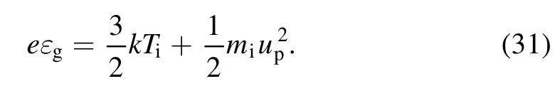
(e) Assuming that the ion temperature inside the discharge chamberTiis equal to the neutral gas temperatureTgand the ion axial velocity at the outlet of the thrusteruiis equal to the axial velocity of neutral gasug,i.e.ui=ug=up[13].Here bothTiandTgare unknown parameters and will be determined by the model equation.Thus, the specific impulse at the outlet of the thrusterIspcan be obtained fromwheregis the acceleration of gravity.
(f) Let the ionization rate of the propellent at the outlet of the discharge chamber beηand assume that the unionized neutral gas in the discharge chamber is uniform [13] with a number density ofng=ηn0.This assumption is reasonable,which means that a portion of the neutral gas will be ionized at the outlet of the discharge chamber [17].
In this work, the ion-number equilibrium equation and the energy balance equation within the discharge chamber are established, both of which are the function ofTe,Ti, and we can getTeandTiby solving these equations.At the first, we give these two equations below directly.
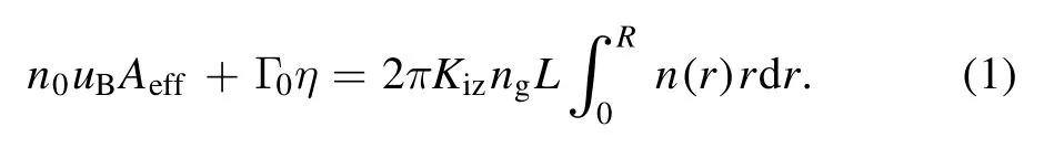
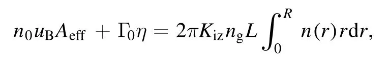
Ion-number equilibrium equation:
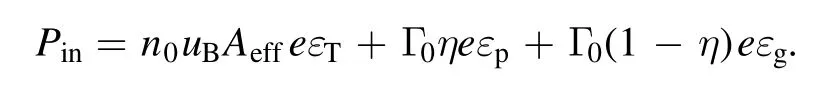
Energy balance equation:

Among them, the left side of the ion-number balance equation indicates the number of ions lost in the discharge chamber per unit time, which is equal to the number of ions produced in the chamber per unit time expressed at the right side.The left side of the energy balance equation is the energy injected into the plasma per unit time(thruster power),and the right side is the energy lost by the particles in the thruster per unit time.In the following part, we will introduce these two equations separately.
2.2.Ion-number balance equation
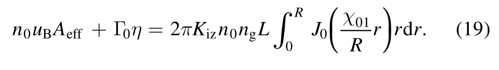
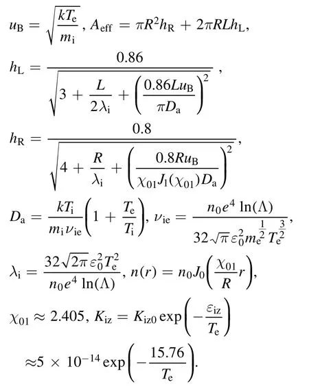
According to equation (1) and the assumption (b), it can be seen that the loss of ions at the wall surface comes entirely from the anode surface as well as from the left end surface of the discharge chamber.The first term on the left side of the equationn0uBAeffrepresents the recombination of electrons and ions at the wall of the discharge chamber,andn0denotes the ion number density at the axis of the discharge chamber,uBdenotes the Bohm velocity, andAeffdenotes the effective loss area of the anode wall.


and
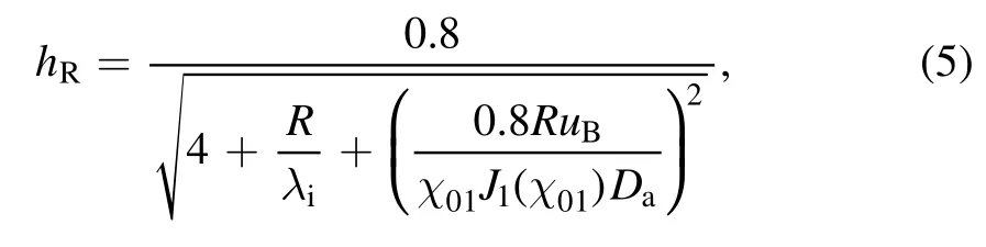
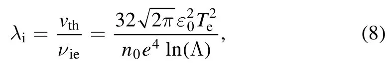
whereλidenotes the ion mean free path, andχ01≈2.405 denotes the first root of the zero-order Bessel function,andJ1denotes the first-order Bessel function, andDadenotes the ambipolar diffusion coefficient, and its expression is
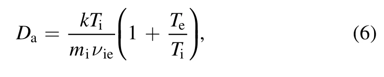
whereυieis the ion–electron Coulomb collision frequency
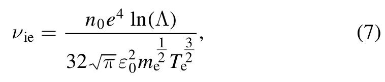
where (Λ)lnis the Coulomb logarithm, which is generally taken as(Λ) ≈ln 10.The high pressure condition [16]mentioned above means that the mean free path of the ionλiis much smaller than the characteristic spatial scale of the system, i.e.whereLsdenotes the characteristic length of the system.Since the propellant ionization rate in high-power SF-MPDTη≥0.9, the Coulomb collisions between ions and electrons play a dominant role, and the mean free path of Coulomb collisions between electrons and ions is mainly considered

This makes it obvious thatn0uBAeffdenotes the number of electron–ion pairs flowing to the wall of the discharge chamber per unit time,all of which are lost in the recombination collision at the surface of the chamber wall.This gives us the analytical expression for the first term on the left side of the equation,which as a function ofTi,Te.
The second term on the left side of the ion-number balance equation (1) denotes the number of electron–ion pairs ejected from the outlet of the discharge chamber per unit time,andΓ0is the particle flux inside the discharge chamber,andηis the ionization ratio of particles.Γ0is determined by the propellant mass flow rateΓmfrom Γ0= Γm/mi.The left two terms indicate the loss of ions in the discharge chamber per unit time.
The right-hand side of the ion balance equation indicates the number of ions produced in the discharge chamber per unit time,and ions are produced from the ionization collision between electrons and neutral particles in the discharge chamber.Kizis the rate coefficient of ionization collision between electrons and neutral particles, the expression is
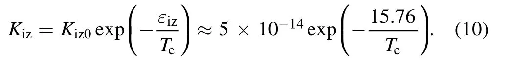
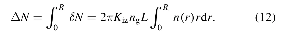
εizis the first ionization energy of the argon atom, which is 15.76 eV [19].In a cylindrical spherical shell with radiusr,lengthLand thicknessrd , the number of ions produced by electron ionization collision per unit timeδNis given by

Therefore, the number of ions produced per unit time in the whole discharge chamberΔNis
Therefore,our aim now is to obtain the spatial distribution of the ion number density in the discharge chamber.Since we assume in assumption (d) that the plasma velocity inside the discharge chamber is low and the density is uniform along the axial direction, we can use the diffusion equation inside the discharge chamber.

Expanding equation (13) in an axially homogeneous axisymmetric column coordinate system

This is a Bessel equation, which has the following solution

Considering the boundary conditions, at the cylindrical plasma boundary, i.e.at the sheath boundary of the anode wall surface,combined with the empirical solution mentioned above, we have

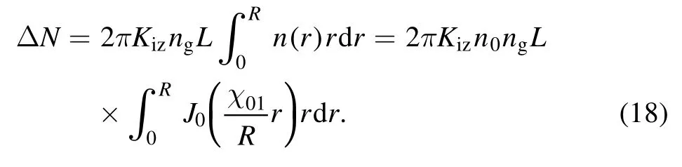
Generally in a typical MPDT discharge chamberhR~10−4,so we can obtainwhereχ01≈2.405is the first zero point of the zero-order Bessel function.From this point, we approximately obtain the ion number density distribution within the discharge chamber as

Substituting the above equation into theΔN, we can obtain
This is the source term on the right side of the equation,which represents the number of ions produced per unit time inside the discharge chamber.Thus,the complete ion number equilibrium equation can be written as
2.3.Plasma energy balance equation
In equation (2) where the left-hand side of the equationPinrepresents the thruster power, which is equal to the total power injected into the plasma.The right side of the equation represents the total energy loss per unit time of the plasma.The total energy loss per unit time of the plasma in the discharge chamber is divided into three parts: the energy contained by the electron–ion pairs loss at the wall,the energy carried out at the exit by the electron–ion pairs, and the energy carried out at the exit by the neutral gas.The first term on the right siden0uBAeffeεTindicates the total energy loss by the electron–ion pairs at the wall, and we have

εcdenotes the collisional energy loss when generated a single electron–ion pair, including the energy loss from ionization,excitation and polarization collisions, which is expressed as[16]
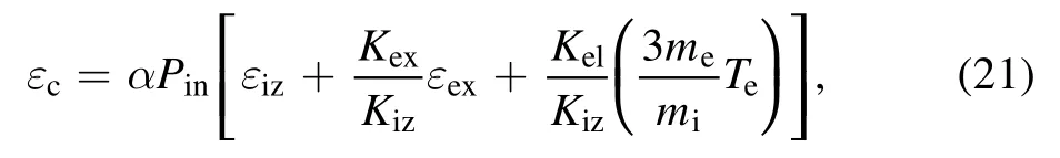
where the energy loss per electron–ion pair produced is proportional to the input power with the proportionality factorα=4.2 ×10⁻⁶W−1.εiz= 15.76 Vis the first ionization energy of the argon atom,andεex= 12.14 V is the excitation threshold of an argon atom, andis the average energy loss per electron during the polarization scattering process.Kizis the ionization rate coefficient and has been given above.Kex,Kelare the excitation rate coefficient and polarization collision rate coefficient, respectively.The experimentally fitted data ofKexandKelare shown below [19]

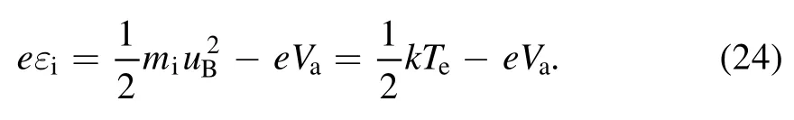
εidenotes the kinetic energy carried by ions bombarding the wall,which comes from the sum of the kinetic energy of ions before entering the sheath and the kinetic energy gained by ions crossing the sheath.This part of energy will be lost in the wall,while the average kinetic energy of irregular motion for a single ion is equal to the average kinetic energy of irregular motion for a single neutral atom after ion and electron recombination because the ion temperature is equal to the neutral atom temperature in the steady-state case.Thus the kinetic energy of the irregular motion of the ion does not change before and after collision with the wall, i.e.the ion temperature remains unchanged before and after the collision,and the kinetic energy carried by the irregular motion will not be counted as energy loss.In SF-MPDT, the voltage of the anode sheath layerVais usually very low [20, 21] (about 1 −2 V) and has little relationship with the thruster power.As a result,the anode sheath voltage is set to a constant value in this paperVa=1 V.In the weak sheath layer formed on the anode surface, the ions enter the sheath layer at a speed of Bohm speed and are decelerated by the sheath electric field in the sheath layer, and the energy of each ion reaching the anode surface is
We supposed that all electrons entering the sheath will be lost at the wall, so the energy lost by all electrons is equal to the average energy carried by a single electron multiplied by the electron flux flowing to the wall.Assuming that the electrons satisfy the Maxwell distribution,the average energy carried by a single electron can be found by the following method.Taking a plane asxoy, and the average energy carried by a single electron is equal to the energy flux carried by electrons divided by the electron flux flowing through thexoyplane along thexaxis, i.e.
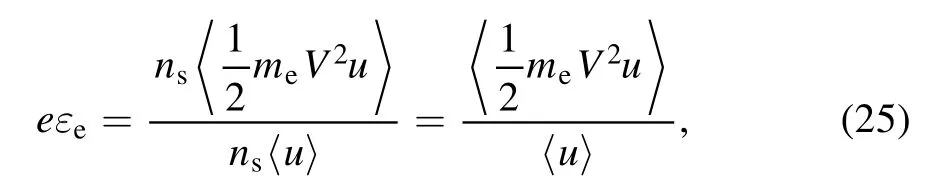
whereV2=u2+v2+w2is the square of the velocity of the electron, andu v w, , are the velocities alongx,y,z.The numerator in the above equation can be written as
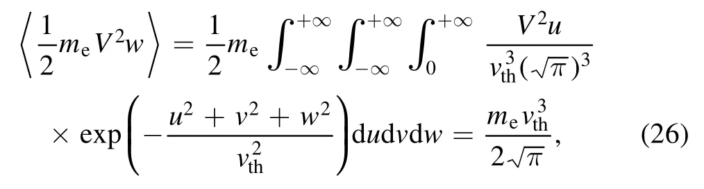
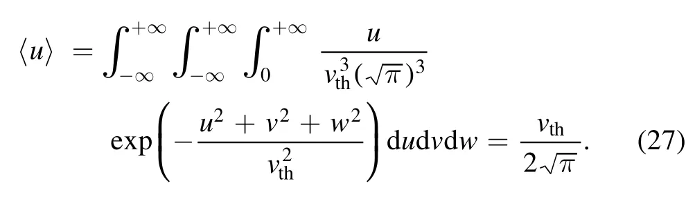
So we can obtain
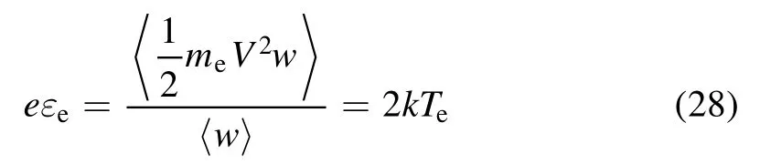
and finally we have

Let us now focus on the second term on the right-hand side of the energy balance equation,where the energy carried away by an electron–ion pair at the outlet of the discharge chamber is
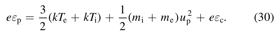
The right-hand side of equation (30) includes the kinetic energy of irregular thermal motion, the kinetic energy of directed motion, and the collisional loss of the generation of electron and ion, respectively.Similarly, the energy taken away by an Ar atom at the exit is
Therefore, the second and third terms on the right-hand side of the energy balance equation (2) represent the energy taken away by the plasma and the neutral gas at the outlet per unit time respectively, both of them are the function ofTi,Teaccording to the above analysis.
2.4.Summary of the model
The plasma equilibrium model within the discharge chamber is summarized as follows.
(1) Ion-number equilibrium equation
where
(2) Plasma energy balance equation
Among them

It can be seen that when the thruster powerPin,the plasma exit velocityup,the particle flux rateΓ0,the ionization rateη, the plasma density in the center of the discharge chambern0and the thruster geometry are determined, both equations are the functions ofTe,Ti.Therefore, we could obtain the average electron temperature and average ion temperature in the discharge chamber by solving the set of plasma balance equations if the above input parameters are determined.At the same time, we can also estimate the chamber pressure by using whereptis the total pressure at the center of the discharge chamber, andpi,pe,pgare the pressures at the center of the discharge chamber for the ionic fluid,the electronic fluid and the neutral gas,respectively,andTg=Tiis the temperature of the neutral gas.WhenTe,Tiare known, we can estimate the pressure inside the discharge chamber based on the above equation.


Table 1.Operation parameters of examples.
Also, we can see that when the thruster geometryR,L,input powerPin,propellant mass flow rateη, central plasma densityn0are all determined,we could obtain the relationship between plasma parametersTe,Tiand plasma outlet velocityupin the discharge chamber.If a reasonable estimate ofTe~ 1 −10 eV,Ti~ 0 −1 eV are determined, we could obtain a reasonable interval for the specific impulse of the thruster, and then bythe thrust efficiency interval is calculated.Thus, the plasma equilibrium model allows us to predict the thruster performance, which can provide a reference for the design of thrusters.
3.Results and discussions
From the above discussion we get that there are two main applications of the model.
(1) Under the thruster parametersR,L,Pin,Γm,η,n0,Ispare determined,the model could be used to calculate the average electron temperatureTeand average ion temperatureTi.
(2) With known thruster parametersR,L,Pin,Γm,η,n0,Isp,we could solve for the specifci impulseIspand the efficiencyχof the thruster with estimatedTe,Ti.
In the first subsection, four typical operating conditions were selected, and the average electron temperatureTeand average ion temperatureTiof the plasma inside the discharge chamber were obtained from the model.We compared theseTe,Tiwith experimental or simulation results.In the second subsection, a SF-MPDT of NASA Glenn Research Center(GRC) were taken into consideration.A range of operating conditions were considered and the specific impulseIspand the efficiencyχwere obtained in a variety of thruster powerPinand mass flow ratesΓm.
3.1.Calculation of the temperature in the discharge chamber
In this part, three simulation examples [13, 22] and one experimental example [23] were selected and the operating parameters of these four examples were input into the model to calculate the average electron temperatureTeand the average ion temperatureTi,andTe,Tiare compared with the experimental or simulated data in the [13, 22, 23].
In the calculation process, the following parameters of the thrusterR,L,Pin,Γm,η,n0,Ispwere given in advance,andTe,Tican be solved by the plasma equilibrium equation.The results are exhibited in the following table 1.
The experimental data and results of calculations of four examples are shown in table 1.It is suggested that the average electron temperature and the average ion temperature calculated by the model are in good agreement with the experimental or simulation results in the reference.Therefore, the model is more reliable for the estimation of electron temperature and ion temperature in the discharge chamber.
3.2.Prediction of thruster specific impulse and thruster efficiency
From the mention above, the specific impulseIspand efficiencyχof the thruster can be predicted from the equilibrium model proposed as a reference for the design of the thruster.In this subsection,the plasma equilibrium model will be used to calculate the specific impulse and efficiency with the variation of the thruster power of GRC-MPDT, and the results will be compared with that in the experiment [24].
The method is described as follows, fristly the thruster discharge chamber geometryR,L, the thruster powerPin,the gas supply folw rateΓm,the average ionization rateηof the neutral gas and the plasma densityn0in the center of the discharge chamber should be determined, and the electron temperatureTeand ion temperatureTiin the discharge chamber are needed to be estimated asTe~1– 10 eV,Ti~0– 1 eV in general.Consequently, the above parameters are substituted into the plasma equilibrium equation and the thruster specific impulseIspcould be estimated, and then the thruster efficiency can be obtained by[25].Since the plasma equilibrium model contains two equations,solvingIspwith a definite solutionTe,Tiwill probably result in the two equations not being satisfied at the same time,so the shooting method is used to determineIsp.Specifically, theTeandTiwere obtained bychanging the differentIspwith the equilibrium equation.When it falls in the estimated interval, the process was finished, at which time we obtained the thruster specific impulse we want.It is suggested that the thruster specific impulse and efficiency obtained by this method can well reflect the real thruster parameters.
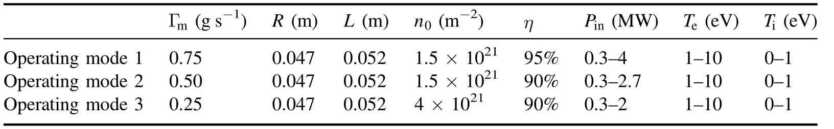
Table 2.Operation parameters of examples operating modes.
Considering the discharge chamber with short and thin cathodes, the difference between the radii of the inner diameter of the anode and the outer diameter of the cathode was treated as a reasonable estimate of the radius of the discharge volume of the chamber, so the geometry of the chamber is taken as=R0.047 m and=L0.052 m, and the other parameters of the thruster are listed in table 2.
After determining the input parameters and the estimated interval ofTeandTi,the next calculation process is to select a lower plasma outlet velocityupand then calculateTeandTi.If the calculation result is not within the estimated interval, one could increaseupand repeat the above steps until they fall within the estimated interval.The minimumupwe obtained in this process is considered as the reasonable estimated plasma outlet velocity.Then we could useto obtain the specific impulseIspand the efficiencyχof the thruster [26].
The calculation results and the experimental data of GRC-MPDT are shown in figures 4 and 5,here the dots with green triangle, blue square and red circle stand for the experimental data under the working condition Γm=0.75 g s−1, 0.50 g s−1, 0.25 g s−1respectively, and the other dots with blue half-triangle, blue half-square and pink halfcircle stand for the calculation results of the model under the operation conditionΓm=0.75 g s−1, 0.50 g s−1, 0.25 g s−1respectively.Figure 4 shows the variation of thruster specific impulse with power, and figure 5 shows the variation of thruster efficiency with power.In figure 4,it is suggested that the model calculation results of the thruster specific impulse versus power were in good agreement with the experimental results.While for the relationship between thruster efficiency and power, the model results are in good agreement with the experimental results under the two operating conditions with the gas flow rateΓ =−0.75 g s01and−0.25 g s ,1and the model calculation results are higher than the experimental results under the operating conditionsΓ =0.50 gs .0−1This is probably due to the method of calculating thruster efficiency,i.e.the formula (33)

Figure 1.Schematic with applied and induced fields and currents and electromagnetic forces of (a) SF-MPDT and (b) AF-MPDT.
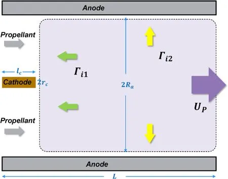
Figure 2.Section view of the chamber.

Figure 3.Three-dimensional view of thruster.
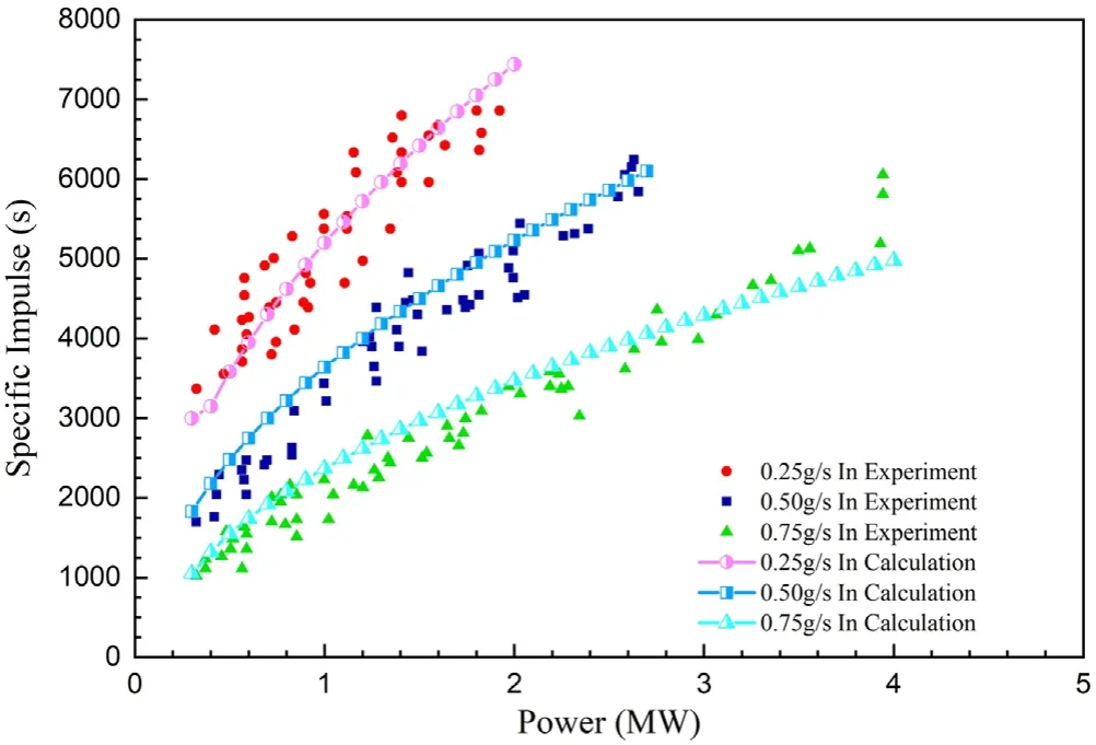
Figure 4.Specific impulse versus power.
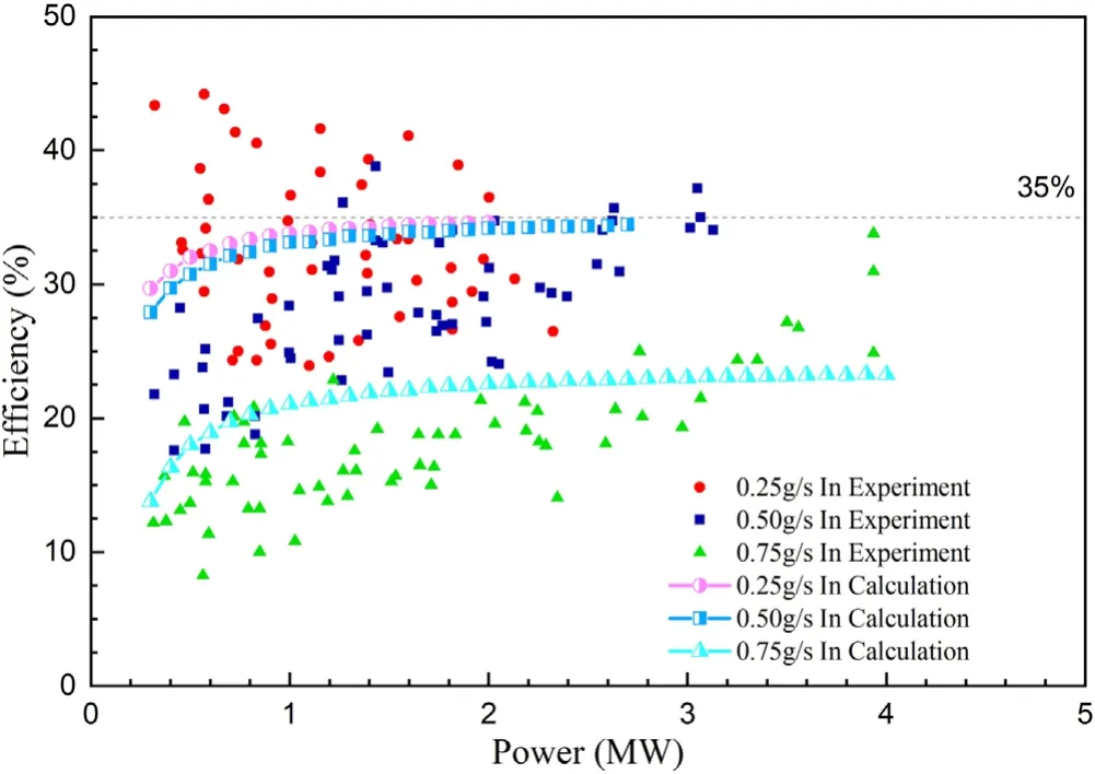
Figure 5.Efficiency versus power.

As shown in figure 4, the thruster specific impulse calculated by the model is slightly higher than the experimental data when the thruster is at lower power(Pin≤1.2 MW)under the operating condition of the thrusterΓm=0.50 g s−1.However, the efficiency is proportional to the quadratic of the specific impulse asχ∝and thus the difference between the model calculation and the experimental measurement is magnified in figure 5, which leads to the result that the model calculated efficiency for the operating conditionsΓm=0.50 g s−1are higher than the experimental efficiency in the lower power range (Pin≤1.2 MW).
In conclusion, the calculated results of the plasma equilibrium model agree well with the experimental measurements in all the operating conditions as described above,which indicates that the model can estimate the performance of the thruster reliably and thus provide a reference for the design of the thruster.
4.Summary and conclusion
In this work,a model based on the equilibrium equation of the plasma inside the discharge chamber is proposed, which could estimate the average electron temperature and the average ion temperature inside the discharge chamber conveniently.In addition, the model can estimate the specific impulse and efficiency of the thruster.The model is used to calculate the plasma parameters under several operating conditions and the results are in good agreement with the experimental or simulation data.Meanwhile, this paper illustrates the reliability of the model in predicting the thruster performance by calculating the variation curves of specific impulse and efficiency versus power for a selected thruster under different operating conditions.In summary, this model has great practical value in calculating plasma parameters and predicting thruster performance.
Acknowledgments
This work was supported by National Natural Science Foundation of China (No.11872093).
猜你喜欢
杂志排行

Plasma Science and Technology的其它文章
- Special issue on selected papers from CEPC 2020
- Surface treatment of titanium dioxide nanopowder using rotary electrode dielectric barrier discharge reactor
- Application study on plasma ignition in aeroengine strut–cavity–injector integrated afterburner
- Microanalysis of a ductile iron by microchip laser-induced breakdown spectroscopy
- Study on water treatment effect of dispersion discharge plasma based on flowing water film electrode
- Decontamination of infected plant seeds utilizing atmospheric gliding arc discharge plasma treatment