Hydrogen isotopic replacement and microstructure evolution in zirconium deuteride implanted by 150 keV protons∗
2021-10-28ManZhao赵嫚MingxuZhang张明旭TaoWang王韬JiangtaoZhao赵江涛PanDong董攀ZhenYang杨振andTieshanWang王铁山
Man Zhao(赵嫚) Mingxu Zhang(张明旭) Tao Wang(王韬) Jiangtao Zhao(赵江涛)Pan Dong(董攀) Zhen Yang(杨振) and Tieshan Wang(王铁山)
1School of Nuclear Science and Technology,Lanzhou University,Lanzhou 730000,China
2Institute of Fluid Physics,CAEP,Mianyang 621900,China
3Sino–French Institute of Nuclear Engineering and Technology,Sun Yat-Sen University,Zhuhai 519082,China
Keywords: zirconium deuterides,isotopic replacement,proton implantation,microstructure evolution
1. Introduction
A neutron generator based on the deuteron–triton (D-T)reaction has many applications in measurement cross-section for nuclear reactions,fusion reactor material irradiation,neutron activation analysis,and other industry fields.[1–3]The tritiated metallic film where the D-T reaction occurs is one of the important components of a neutron generator.[4,5]In recent years, zirconium tritiated (ZrTx) is chosen as a candidate material for the target film because of the excellent hydrogen storage properties[6,7]and higher thermal stability than titanium tritiated (TiTx).[8,9]However, the neutron beam flux and duration are influenced by the target film properties during D ions implantation. It is known that tritium replacement by implanted deuterons will result in the decrease of tritium concentration which reduces the intensity of the 14 MeV neutron.[10,11]Furthermore, the D ions implantation can significantly influence the integrity of structural components with the formation of voids, surface swelling, blistering and even crack,exfoliation in the tritium target.[12–15]Thus,the knowledge of the hydrogen isotopes effect and the microstructural changes of the target,is of essential importance for the assessment of the target lifetime.
In the previous studies,Doyle and Blewer have observed the exchange of hydrogen isotopes in titanium compounds and established several models to explain.[16–18]Hugheyet al.have also discussed the physical mechanisms of tritium replacement by implanted deuterons.[11]Further, Karamaniset al.have conceived a collisional displacement model to explain tritium release from TiTxtarget.[19]Many attempts have also been made to investigate the effects of hydrogen isotopes irradiation on the target structure.[20,21]Yang and Liuet al.have observed the cracking feature and phase transformation of titanium hydride film under irradiation of energy density close to 0.5 J/cm2.[22]Astrelinet al.[23]have investigated the blistering process on the surfaces of long-lifetime neutron-generating targets irradiated by an intense 200 keV proton beam. However, there were no sufficient studies on the interaction between hydrogen isotopes and ZrTximplanted with massive D ions, especially the isotopic exchange and hydrogen damage in this new kind of target film candidate.
Deuterium and tritium,as two different isotopes of hydrogen, have similar chemical properties. Therefore, the properties of the tritium target were often studied by proton implantation to avoid neutron generation.[11,23,24]In this work, the phenomena of isotopic replacement and microstructure evolution in ZrDxunder 150 keV protons implantation were studied instead of ZrTxtarget irradiated by deuterium ions. The depth profiles of retained H and D in the zirconium deuteride film were obtained by elastically recoil detection analysis(ERDA)combined with time of flight-secondary ion mass spectrometry (ToF-SIMS), which is one of the most useful methods to evaluate the concentration of hydrogen isotopes in materials.An analytical model was proposed to analyze the experimental data. Furthermore, the x-ray diffraction (XRD) analysis and scanning electron microscope(SEM)/energy dispersive xray spectroscopy(EDS)were conducted to understand the microstructure variation induced by proton implantation.
2. Experiment
2.1. Preparation of ZrDx films
Molybdenum(Mo)film with a thickness of about 0.5µm was deposited on the polished silicon substrate by magnetron sputtering method as diffusion suppression layer. Then, this Mo film with Si substrate was rinsed with mixed acid (nitric acid and sulfuric acid) and washed in deionized water subsequently. To remove surface contamination, the film was cleaned with acetone in the ultrasonic cleaner for 30 minutes and dried under a nitrogen atmosphere. After that, the ZrDxfilm (~3.4 µm) was grown on the molybdenum layer by one-step reactive magnetron sputtering at 573 K substrate temperature and 250 V DC substrate bias. High purity argon(99.999%)gas and deuterium(99.999%)gas were used as the sputtering gas and reactive gas, respectively. A metallic Zr target of high purity (99.95%) was utilized as sputtering targets to deposit the ZrDxfilms. The base pressure was about 10−5Pa.The total pressure of the(Ar+D2)gas mixture was set at 0.4 Pa,while the rate of Ar flow and D2flow was 10 SCCM and 20 SCCM,respectively.
2.2. Proton implantation
For proton implantation experiments, the samples were mounted on a sample holder with a conductive adhesive tab in the chamber at the 400 keV ion implanter (NEC Corporation) of Xiamen University. They were exposed to 150 keV protons beams with the different fluence of 1×10¹⁶, 3×1016,1×1017,and 1×10¹⁸protons/cm2. A proton beam with a current below 50 µA/cm2was implanted to all specimens at an angle of 90°against the target specimen under high vacuum conditions. The chamber vacuum of 5×10⁻⁴Pa can generally be achieved by using molecular pumps during ion beam implantation. The proton beam was raster scanned over each specimen to produce uniform damage during the irradiation.The temperature of the sample holder was controlled at room temperature (RT) by a water cooling system as continuously monitored by a thermocouple placed near the sample.
As presented in Fig.1,the displacement damage and protons deposition distribution profile of 150 keV proton beam implantation at the fluence of 1×10¹⁸protons/cm2have been calculated by SRIM-2008. It can be clearly seen that the maximum penetration depth of 150 keV protons in ZrDxfilm is~855 nm and the maximum damage values at the Bragg peak position are calculated to be~3.6 dpa.
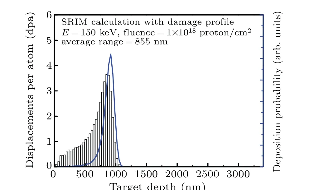
Fig. 1. The depth-dependent damage distribution and protons deposition peak of 150 V proton calculated by SRIM results.
2.3. Characterization methods
The H and D concentrations within the near-surface layer(about~0.3µm)were measured by ERDA using at 1.95 MeV helium ion beam with a 75°incident angle, and the energy spectrums of emittedαparticles were measured by an Au–Si surface barrier detector at the scattering angle of 30°in laboratory coordinate system. In addition, the composition of the film was determined by RBS with a 1.305 MeV proton ions beam perpendicular to the sample surface. The ERDA and RBS spectra were transformed into depths profiles using the SIMNRA program.[25]Based on the RBS and ERDA measurements, the average atomic ratios of D/Zr and H/Zr at the near-surface layer (~0.3 µm) were obtained as presented in Table 1. And the results of the original sample were similar to those with an implantation fluence of 1×10¹⁶protons/cm2and were not listed separately.
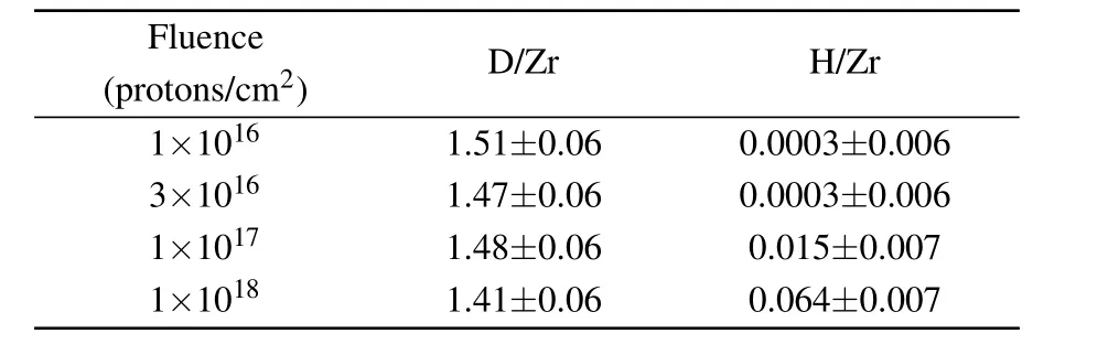
Table 1. The average atomic ratios of D/Zr and H/Zr were obtained by ERDA at the near-surface layer (~0.3 µm) on different implantation fluence.
To determine more accurate depth profiles of the film H, D and Zr concentrations at greater depths, ToF-SIMS measurements[26]were conducted with a ToF-SIMS V spectrometer (ION-TOF GmbH, M¨unster, Germany) equipped with a Bi liquid metal primary ion source. 30 keV Bi+beam with a current of 1.34 pA was used as the analyzing beam,which was rastered over a 50×50µm area. In the negative ion signal mode,for D and H in ZrDx,2 keV Cs+ions with a current of about 100 nA were applied because of its significant enhancement of negative ions yield. In addition, a time-offlight detector was employed to measure the secondary ions from the surface and the data collection time is 5000 s. Additionally,in the positive ion signal mode,a 2 keV O+2ions beam at a current of 400 nA spread across 300×300 µm2with the sputtering time of 1000–2000 s was performed to analyze the depth profile of metal ions. The chamber pressure was maintained at about 3.1×10⁻⁷Pa during each acquisition. ION -TOF Surface Lab software (ION-TOF GmbH, M¨unster, Germany,version 6.0)was used to analyze the original data.
TOF-SIMS provides well-resolved concentration depth profiles, and the shortcomings of absolute quantification could be compensated by ERDA measurement. Therefore,the SIMS counts were multiplied by a correction factor ofNERDA/NSIMS(50−300nm)to get the absolute H and D depth profiles. Here, SIMS counts at a depth range of 50–300 nm were chosen to avoid the H/D absorption peak at the surface.
The surface morphology of the film surface was observed by SEM/EDS.The XRD patterns of the ZrDxsamples before and after protons implantation were recorded using CuKαline by D/max-2400 (Rigaku Corporation) with a grazing incidence angle of 1°, operating at 40 kV voltage and 40 mA current to obtain the phase structure features especially within the implanted surface of ZrDxsamples. And the XRD patterns were analyzed by MDI Jade 6.0.
3. Results and discussion
3.1. Depth profiles analysis
The depth profiles of H/Zr and D/Zr atomic ratios measured by a combination of SIMS and ERDA are shown in Fig. 2. A swift dip is found in the region of 0–50 nm, which is caused by surface absorption of H from the air and has no relation to the proton implantation. It can be seen from Fig. 2(a) that the atomic ratio of H/Zr increases with proton fluence. At the lower fluence, it indicates that hydrogen distributes homogeneously throughout the thickness of the ZrDxthin film.For fluence in the range from 1×10¹⁷protons/cm2to 1×10¹⁸protons/cm2,a slight decrease of the H/Zr atomic ratio is found in the range of about 600–750 nm. In addition, two flat H/Zr depth profiles can be observed,and the crucial change happens to 600–750 nm. This is less than the implanted range simulated by SRIM software as shown in Fig. 1. The difference is mainly ascribed to the fact that the SRIM code does not consider the H atoms diffusion in lattice or be trapped by defects. Some implanted protons are trapped in defect areas induced by proton irradiation and forms the higher profile region, which grows up and shifts to deeper with the implantation fluence. While many H atoms cannot be trapped and stay at interstitial positions temporarily,and then would diffuse to a low concentration zone driven by concentration gradient in the full film according to Fick’s law,[27,28]which is consistent with the previous investigations.[29–31]
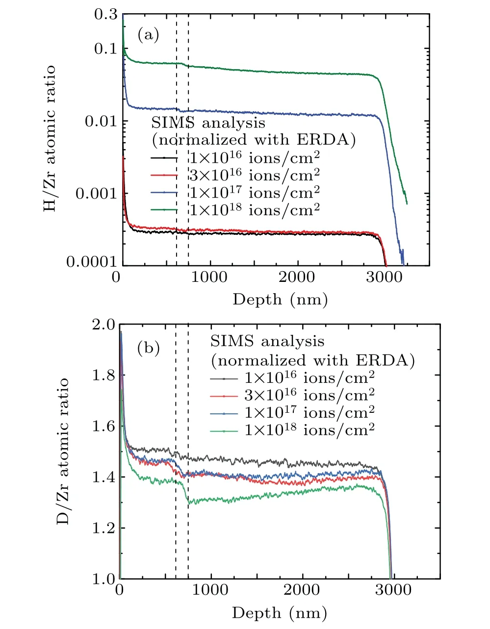
Fig. 2. Depth profiles of H/Zr (a) and D/Zr (b) by SIMS normalized with ERDA at various implantation fluence.
In addition,as shown in Fig.2(b),the atomic ratio of D/Zr decreases with proton irradiation, which is caused by both forming of zirconium hydride and the release of free D by diffusion. A sharp decline appears at about 600–750 nm,which corresponds to the severe irradiation damage region (Fig. 1).It can be explained by the decomposition of deuteride(Zr-Dx)and the decrease of the D/Zr ratio caused by proton damage at the end range. For these values of deuterium concentration here, theαandγphases are guessed to form, where the D (H) atoms are in the quasi-free and semi-stable state,respectively.[32,33]Thus,resulting in the D(H)atoms are easy to diffuse and deuteride(hydrides)is not easy to recombine in this region.
It is evident that the H concentration increases,while the D concentration decreases in the whole ZrDxfilm with proton fluence. Because D and H have the same chemical properties, the exchange between H and D atoms could happen in the whole film with some probability. Zr-Hxcould be therefore formed in proton implanted ZrDxfilm. But inside of the proton range,Zr-Dxdecomposition was caused by irradiation,and the exchange probability was significantly enhanced due to the free Zr recombines with H. This similar replacement phenomenon of hydrogen isotopes has also been demonstrated by Doyle.[16]Consequently,it is confirmed there was obvious replacement behavior in the ZrDxfilm during protons implantation from the depth profile.
3.2. Model of isotopic replacement behavior
In order to further investigate the replacement behavior of hydrogen isotopes with the increase of proton fluence, the atomic ratios of H/Zr and D/Zr in the range of 0.3–0.5µm are averaged. This range is determined to avoid the influence of surface effects and irradiation damage. For the depth deeper than 0.6µm,as shown in Fig.2(b),a dramatic decrease of the D/Zr ratio occurs because of severe damage indicated in Fig.1(SRIM). The experimental values of average atomic ratios of D/Zr and H/Zr as functions of proton fluence are presented in Fig. 3, in which the H/Zr is multiplied by 10 to show the data more clearly.Obviously,an increase of the proton fluence from 1×10¹⁶to 1×10¹⁸ions/cm2leads to an increase of H/Zr from 0 to 0.0626,whereas the D/Zr decreases from 1.51±0.06 to 1.39±0.06,with a total decline of D/Zr about 0.12.

Fig. 3. The proton fluence dependence of the average atomic ratio of D/Zr, H/Zr and (H+D)/Zr in the surface layer (0.3–0.5 µm) of ZrDx film. The dotted and dashed lines are theoretical fitting of retained D/Zr and H/Zr atomic ratios.
In previous work, Hughey indicated that the loss of tritium away from range-end can be attributed to beam enhanced detrapping of tritium from its bound sites and subsequent refilling of the vacant sites with implanted deuterons.[11]In Blewer and Doyle’s works,[16–18]a decay modelND=Ns·exp(−σ·nH) was explicitly proposed to explain the deuterium amount remaining in the lattice after a proton fluencenH. According to these models,we assume
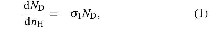
whereNDis the D/Zr ratio at proton fluencenH,andσ1is the deuterium detrapping cross-section, which describes the deuterium detrapping probability when irradiated by protons.This leads to a solution as following:

whereNsis saturated D/Zr ratio before proton implantation.This fact(Fig.3)indicates that the decay equation reproduces excellently the experimental results.
For the H/Zr ratio, Doyleret al.[16]assumed that additional hydrogen coming to the rest in the saturated region would find available trapping sites when the previously trapped deuterium is detrapped, and free atoms which could not be trapped would escape from the target surface. And they believed that the summation of two types of hydrogen isotopes should be constant at the saturated region,i.e.,ND+NH=Ns,which leads to dNH/dnH=−dND/dnHand is different from the result observed in this experiment. In our work,the number density of trapping sites~0.12NZr(NZris the atomic density of Zr in ZrDxfilm) is obtained through the detrapping process induced by proton irradiation at maximum proton fluence of 1.0×10¹⁸ions/cm2. However, only~0.06NZrsites are occupied by incoming proton. This difference at high ion fluence may result from structure modifications caused by ion irradiation. As the protons fluence increased, the concentration of gas-filled voids within the sub-surface layer increases,and interconnected porosity starts to develop after certain fluence.[12]This leads to the recombination and release of a fraction of the molecular hydrogen. Therefore,according to our experiment results, the amount of retained protons is described separately by Eq.(3)as follows:

which means the increase of H/Zr ratio per unit flux of protons is proportional to the available trapping sites (Ns−ND),whereσ2is defined as trapping cross-section of the proton by trapping sites. Combining Eqs.(2)and(3),we get

Equations(2)and(4)give the variation behavior of D/Zr ratio and H/Zr ratio with an increase of proton fluence. As shown in Fig. 3, the trends of D/Zr and H/Zr ratio with the increase of proton fluence are described reasonably by this model for the isotopic replacement process in our experimental conditions. Here, the number density of saturated trapping sitesNsis 1.48±0.02NZr. For the best fitting, and deuterium detrapping cross-sectionσ1and trapping crosssection of the proton by trapping sitesσ2are determined to be(6.5±2.0)×10−20cm2and(2.2±0.2)×10−20cm2, respectively.
It has been reported that the deuterium detrapping cross-section for D pre-implanted SiC with 5 keV H+2is 2.6×10⁻¹⁸cm2,which is much larger than that for ZrDxwith 150 keV.[34]This is consistent with the trend that the replacement cross-sections decrease monotonically with increasing implant energy, which was illustrated by Blewer’s work.[18]It is considered that the formation of more voids and vacancy clusters at high implant energy leads to the increase of free D atoms in recapture probability. It suggests that the implant energy is one of the factors in determining the amount of deuterium detrapping. The speculation also needs more fully test to investigate.
It could also be concluded that the deuterium detrapping process dominates the hydrogen isotope retention in target film because the deuterium detrapping cross-sectionσ1is 2–4 times of the trapping cross-sectionσ2, which means more deuterium is detrapped,and only the half of available trapping sites are occupied by incoming proton. However, this phenomenon was not observed by Doyler and Bleweret al.[16,18]because the proton energy range in their work was 1–14 keV,which is lower than 150 keV used in our work. In our experiment,the target temperature was at room temperature,which was higher than−120°applied in Blewer’s work. Therefore,hydrogen atoms’ mobility is increased in the experimental conditions of this work,and the enhanced mobility also means the higher escaping amount from the sample surface.[29]This also shows that the isotopic replacement phenomenon is dependent on the beam energy, target materials as well as the target temperature.
3.3. XRD analysis
The XRD patterns of ZrDxspecimens implanted with various proton fluences are shown in Fig.4,the observed diffraction peaks at 32.24°, 36.00°, 52.09°, 54.84°, and 62.38°correspond to (111), (200), (220), (202), and (311) planes, respectively. It can be seen that no additional peaks were found in all the irradiated specimens, and (220) reflection peak has almost disappeared in the diffraction pattern when the proton fluence is 1×10¹⁸. Taking into account the previous investigation,[22,31]it is reasonable to conclude that the lowenergy particles irradiation does not lead to the generation of a new phase in ZrDx, while partial lattice distortion may be caused by the introduction of defects at higher fluence. To further evaluate the microstructure effects of proton implantation in the injected region surface, the calculated crystallite size and microstrain along (111) are given in Table 2.[35,36]With ion fluence increasing from 1×10¹⁶to 3×10¹⁶protons/cm2,the crystallite size increases slightly, but the crystallite size indicates a decreasing trend and microstrain rise by further increasing the proton fluence.However,there is little overall significant difference in values compared with the un-irradiated samples. And according to the previous studies,[22]such results are reasonable due to the limited irradiation effects of low energy protons on the microstructural property of zirconium alloy in implanted region.
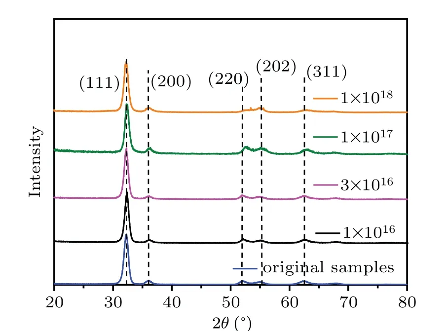
Fig.4. The XRD patterns normalized of the ZrDx samples before and after protons implantation.

Table 2. Structural parameters of(111)plane on various implantation fluence.
3.4. Surface morphology
The surface morphologies of ZrDxspecimens implanted with different proton fluence are shown in Fig. 5. With the increase of protons fluence from 1×10¹⁶to 1×10¹⁷, there is no observable morphological difference in the implantedproton specimens compared to the original, suggesting little mechanical damage due to the proton implantation. This is in agreement with the phenomenon observed in previous studies.[29,30]However, the circular flaking areas with a diameter of about 100µm homogenously distribute in the ZrDxsurface are visible when the implantation fluence increases to 1×10¹⁸proton/cm2(Fig. 5(e)). Compositional analysis of these circular flaking areas is carried out by using energy dispersive x-ray spectroscopy (EDS) presented in Fig. 5(e), and results confirm that the Si substrate (purple area) was completely exposed.

Fig.5. SEM images of ZrDx implanted protons at different dose,(a)without implantation,(b)1×10¹⁶ protons/cm2,(c)3×1016 protons/cm2,(d)1×1017 protons/cm2,(e)1×1018 protons/cm2 under different magnifications,and EDS analysis result was shown as insert in(e).
As mentioned in the previous section,the probability for H atoms trapped by defects in the implanted region is quite less, compared to the number of implanted protons. Most of the H atoms would diffuse to a deeper region,even to substrate at higher fluence, as can also be seen from the depth profiles of H in Fig.2(a). It is noticed that the lattice size of Si crystal grain is 72.48%larger than that of Mo,which could contribute to forming a large amount of mismatch dislocation between the deposited material and the substrate during the growth of the Mo layer on the Si substrate’s surface.[37,38]These H atoms tended to diffuse to these structures and be captured, which could lead the number of H atoms to congregate so that the H micro-bubbles nucleated at the interface. With increasing implantation fluence to 1×10¹⁸protons/cm2, the growing H clusters might eventually reach excessive compressive stress that the pressure disrupted the bubbles to release the H atoms inside,ending with the surface flaking area development. And the growth process of surface damage was similar to the previous results,[15]but in this study,the H atoms were accumulated at the substrate interface due to the intrinsic defects introduced in the preparation process of the target, rather than the defects induced by irradiation. Consequently, the creation of long-living targets requires the selection of suitable alternative substrate materials,such as Nb and Cu.
4. Conclusions
The influence of 150 keV protons implantation on the hydrogen isotopes replacement behavior and microstructure of ZrDxfilm have been investigated with fluence range from 1×10¹⁶to 1×10¹⁸protons/cm2. The D/Zr and H/Zr depth profiles were analyzed by ToF-SIMS combined with RBS and ERDA measurements. The depth profile results demonstrate that the H and D concentrations show a decline at 600–750 nm corresponding to the severe radiation damage region(SRIM).Furthermore,the D/Zr concentration decreases with increasing the proton fluence to 1×1018.A modified model is established to analyze well the retention and decay curves of H and D in ZrDx,which demonstrates the probability is approximately 2–4 times for detrapped deuterium than for H atoms trapped by defects in implanted region.
It is found that no new phase is detected in all irradiated specimens from XRD results and the (220) plane almost disappears when the proton fluence is 1×10¹⁸protons/cm2. Circular flaking zones with a diameter of about 100 µm on the ZrDxsurface are observed from SEM when protons fluence increases to 1×10¹⁸protons/cm2. And EDS results reveal that the Si substrate is exposed from circular flaking zones. The phenomenon may be ascribed to the increase of compressive stress excessive from induced by the H atoms congregation because of metal substrate mismatch dislocation at the interface.This degradation on the film surface could generate a decrease in the performance of the neutron production target. Attention should be paid to the microscale property of suitable substrate materials for a long-living target.
猜你喜欢
杂志排行

Chinese Physics B的其它文章
- Physical properties of relativistic electron beam during long-range propagation in space plasma environment∗
- High winding number of topological phase in non-unitary periodic quantum walk∗
- Widely tunable single-photon source with high spectral-purity from telecom wavelength to mid-infrared wavelength based on MgO:PPLN∗
- Control of firing activities in thermosensitive neuron by activating excitatory autapse∗
- Adaptive synchronization of chaotic systems with less measurement and actuation∗
- Dynamics analysis of a 5-dimensional hyperchaotic system with conservative flows under perturbation∗