Insights into the regulation mechanism of ring-shaped magnetoelectric energy harvesters via mechanical and magnetic conditions∗
2021-10-28YangShi师阳NiLi李妮andYongYang杨勇
Yang Shi(师阳) Ni Li(李妮) and Yong Yang(杨勇)
1School of Mechano-Electronic Engineering,Xidian University,Xi’an 710071,China
2Research Center for Applied Mechanics,Xidian University,Xi’an 710071,China
Keywords: magnetoelectric effect,boundary conditions,magneto-elastic coupling,external stimuli
1. Introduction
The emerging industrial revolution involves the internet of things(IoT),which is the key technology for enabling smart cities.[1]However, although this technology would promote innovation in society, as we would create a network between everything and realize remote distance control of electronic devices,some challenges exist in bringing the IoT to fruition.For example,this concept assumes the very wide implementation of distributed electronic devices to capture data,[2,3]each of which will require energy to run. Batteries in various forms are currently the primary power source for operating these devices. Despite many advantages,batteries are not the ultimate solution because they require periodic replacement or recharging. One of the promising solutions to these issues is harvesting ambient forms of energy,much of which would otherwise be wasted, to power the sensors. Among the various sources of energy,magnetic field is an attractive alternative source because they are available in most of the locations where the wireless sensor networks will be used.
Recently, laminate magnetoelectric (ME) composites,formed by elastically combining piezoelectric and magnetostrictive materials, have been demonstrated as a potential choice for harvesting magnetic signals due to strong strain-mediated ME coupling.[4–6]In the ME effect, an electric field or voltage through the piezoelectric effect is resulted from the mechanical strain induced by an external magnetic field. The strength of the ME coupling in laminated composites depends mainly on the intrinsic property of components,[7]interfacial mechanical coupling,[8–10]and the boundary conditions.[11]Up to date,various investigations have been performed to achieve higher ME coupling coefficient by selecting magnetostrictive and piezoelectric components with excellent properties.[12,13]On the other hand,a great deal of researches have been devoted to further enhance ME coefficient via varying the configuration of ME composites.[14,15]Among various configurations, the diskring, ring-shaped and cylindrical composites show considerable advantages due to improved interfacial mechanical coupling. Unlike the conventional laminated plate or beam, the ring-shaped or cylindrical structures can transfer normal stress instead of shear stress via interface and thus improve the interfacial mechanical coupling.[16]In addition,some advanced fabrication methods, such as electro or electroless depositions,have been successfully used in preparing the ring-shaped composites.[17]This can eliminate the use of epoxy bonding layer or electrodes, and is thereby believed to be advantageous. Wanget al.[8,18]theoretically revealed that ME effect can be substantially enhanced by increasing the curvature of a piezoelectric/piezomagnetic cylinder, and an imperfect interface can annul small unwanted resonance for better device operation. Gao and Zhang[19]modeled the nonlinear ME coupling of a giant magnetostrictive/piezoelectric composite cylinder based on a standard square constitutive model. Most recently, Kumar and Arockiarajan[20]presented an analytical ME model in a cylindrical coordinate system incorporating the temperature effects on the individual composite constituents.These theoretical models have significantly contributed to the theory of ME effect in ring-shaped structures.
Nearly, all prior works on ring-shaped ME composites focused on studying ME coupling with consideration of an open-circuit condition, thus they can only apply for sensing applications rather than harvesters. For the energy harvester using ring-shaped composites,however,the power conversion performance has not got enough attention. There are still considerable difficulties and challenges in the practical application of the ring-shaped magnetic energy harvester. Initially,it has been indicated that available ME effect can be observed only when the intrinsic frequency of structure closes to the frequency of ambient magnetic field.[21–23]However,the magnetic fields from the wireless sensor networks always have random distributions of frequency components, which makes it difficult to match the frequencies of the harvester and ambient magnetic field. Therefore, exploring new regulation mechanism of ME performance becomes one of important issue to be addressed. Mechanical boundary conditions may directly influence the strain distribution in the ring-shaped composites,and improve the performance of energy harvester. The insight into the ME coupling under different mechanical boundary conditions is currently lacking in any of the above mentioned references nor available in the state-of-the-art literature.Moreover,the material parameters(i.e.,elasticity modulus and piezomagnetic coefficient) of magnetostrictive materials are very sensitive to the external stimuli like bias magnetic and stress loadings.[24–28]This enables a new theoretical mechanism for tunable or active manipulation of ME performance of the energy harvester.[29]However, the nonlinear coupled effects of such external stimuli on ME coupling of the ringshaped composites have not been well investigated since most of the theoretical models were established using linear constitutive relations of constituent materials.
The objective of this paper is to model ring-shaped ME energy harvesters and to reveal regulation mechanism via mechanical and bias magnetic conditions. The theoretical model for the energy harvesters based on ring-shaped ME composites is established and the basic equations are introduced in Section 2. Then analytical solutions for the ME coupling in ring-shaped composites and nonlinear field-dependent material parameters are derived in Section 3. In Section 4,some results are presented for tuning the ME performance via boundary conditions and external stimuli. Finally,some conclusions are made in Section 5.
2. Problem description
Figure 1 shows a magnetic energy harvester based on a ring-shaped ME composite. The ME composite is presumed to be assembled from an outer piezoelectric ring concentric to an inner magnetostrictive cylinder. Taking into account the symmetry of the cylindrical structure,a cylindrical coordinate system(r,ϕ,z)is adopted, in which the coordinate directionr,ϕandzwill be designated as 1,2 and 3,respectively,so that the tensor coefficients can keep the same values in a cylindrical coordinate system as those in a Cartesian system. The piezoelectric material is polarized alongzdirection and magnetostrictive material is magnetized along the same direction.Herea,bandcare radiuses as denoted in Fig.1. The ambient ac magnetic field alongzdirection could induce a mechanical strain from the magnetostrictive phase that transfers to the piezoelectric phase via interfacial coupling. Then a change in polarization of the piezoelectric phase results from piezoelectric effect, which is expected to be harvested by an external resistanceRl. Note that in practical applications, the postprocessing electric circuit is very crucial for ME harvesters.Adequate power management circuits have to be applied in electromagnetic energy harvesting to produce appropriate supply performance. In the current work we intend to study clearly how mechanical and magnetic conditions affects ME coupling. Thus,only one-load electric circuit[30,31]is considered,which,however,may not hinder us from evaluating and comparing ME performance under different stress and magnetic loadings. As the height of the cylindrical structure is assumed to be much less than its radius in the current analysis,the only nonzero components of the stress tensor areσrrandσϕϕ. Since for the harmonic motion, all the fields have the same time dependence exp(jωt). This factor will be dropped in the analysis. For macro-scale magneto-electro-elastic media,both flexo-effect and surface effect can be neglected.[32,33]In a cylindrical coordinate system(r,ϕ,z),when such media were operated under the conditions that the body force, free charge density and current density are absent, the mechanical governing equations for the dynamics of the axisymmetric cylindrical ring can be expressed as[34]whereuris radial displacement, andρis the effective mass density of the ring-shaped composites.
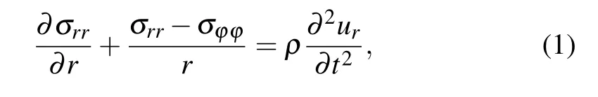

Fig.1. Schematic diagram of magnetic energy harvester based on ringshaped ME composites.
The linear constitutive equations for the stress tensorpσi jand the electric displacementD3in the piezoelectric layer,and stress tensorsmσijin the magnetostrictive layer can be written in terms of displacement as follows:
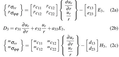
where the left superscriptspandmrepresent piezoelectric and magnetostrictive layers,respectively;ci jkl,eij,di j,anda33are elastic,piezoelectric,piezomagnetic,and dielectric constants,respectively;E3andH3are the components of electric field and magnetic field,respectively.
3. ME coupling in ring-shaped composites
3.1. General solutions for mechanical variables
For solving mechanical variables,we substitute the above constitutive equations into Eq. (1), and rewrite the governing equation in the form of

whereAiandBiare the integration constants determined from interfacial and boundary conditions.J1(·) andY1(·) are the first and second kind Bessel functions. The stresses and electric displacement in the composites are then obtained with combining the above solutions and constitutive relations.
3.2. Mechanical interfacial and boundary conditions
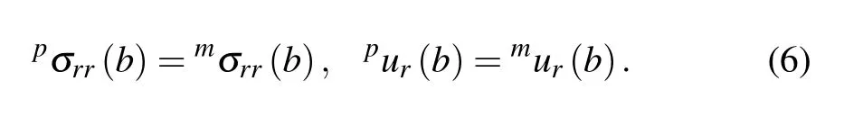
Since the thickness of the interfacial layer caused from adhesives may be very thin compared to the composites, the interface can be classified as a bonding layer-free interface.Thus, perfect interfacial conditions are considered in this study,given by
Some conventional boundary conditions are listed in Table 1, which include stress-free and clamping (zero displacement) separately on the inner and outer radii of the magnetostrictive and piezoelectric layers,respectively. Note that one of the great advantages of the ring-shaped structure is that one can apply normal stress on the inner and outer boundaries,without the concern of interface failure caused by shear stress.In the current study,we propose new mechanical conditions by applying stressP0on the inner radii of magnetostrictive layer or the outer radii of piezoelectric layer. These mechanical conditions can be realized by assembling a concentric cylinder (annulus) with proper dimensions to the ME composites at inner(outer)boundary,since radical direction stress may be produced at boundaries via strong compression. As listed in Table 2, the proposed stress boundary conditions differ from those used in the overwhelming majority of existing analytical models.[19,35]The introduction of these conditions provides a utility for tuning the stress distribution in the composites,hence tuning the overall performance of the magnetic energy harvester. This highlights the first novelty of this study while accounting for possible practical operation issues.

Table 1. List of stress-free and clamping boundary conditions and their mechanical interpretations.

Table 2. List of applying stress boundary conditions and their mechanical interpretations.
Substituting the expressions of the stress tensor and the displacements into the above mechanical interfacial and boundary conditions leads to eight equation sets with respect toAiandBi. These equation sets are then solved for unknown constants and the induced displacements in piezoelectric phase under different conditions can be determined.
3.3. Analytical solutions for electrical variables
In this section,the induced electrical variables are solved.It can be predicted from the above process that the displacement in piezoelectric phase has linear relations with the induced electric field, the applied magnetic field, and external stress applied at the boundaries. For convenience, the displacementpuris rewritten as

The magnetic field harvester schematically displayed in Fig. 1 is operated under closed circuit with a resistanceRl.The induced ME voltage is denoted asVME.Combining Ohm’s law and the integral form of Gauss’s law, we can reach the following relation:
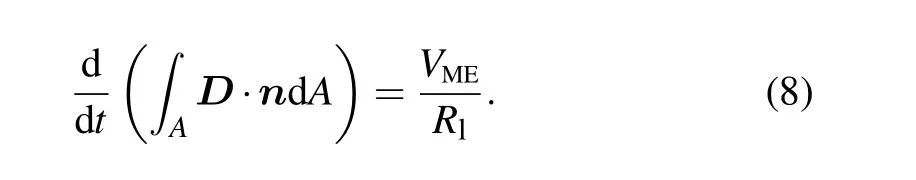
Then using the expression of the electric displacement and considering the relation between the electric field and the voltage,we obtain the expression of the induced ME voltage under closed-circuit condition,given as
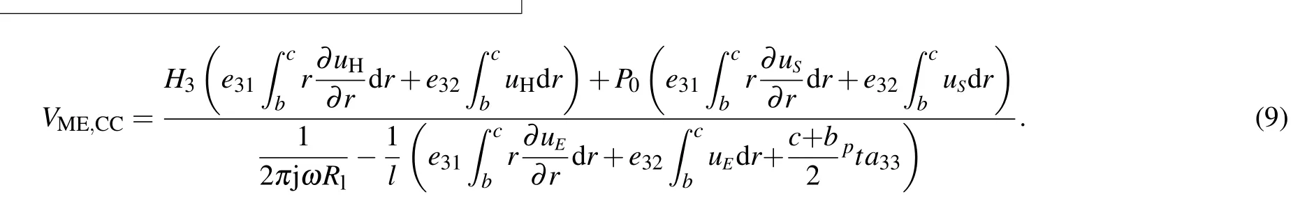
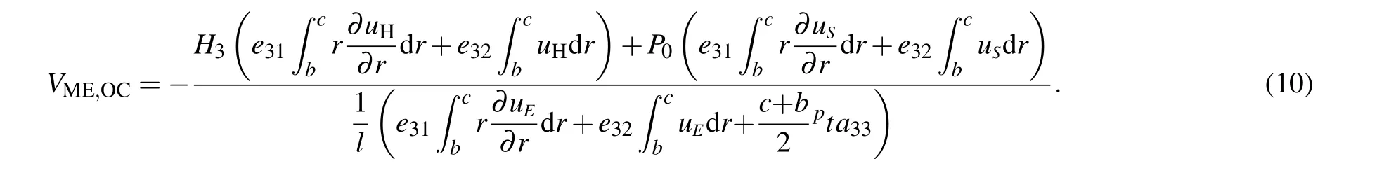
Note that our solutions can also be used to predict the ME effect of ring-shaped composites used as magnetic sensors under open-circuit condition. In this case,the only change is setting the right part of Eq.(8)(i.e.,the induced current)to be zero. That is,Rl→∞yields equation that determines the open-circuit ME voltage as follows:
Hence the ME voltage coefficientαMEand the output power densitypis obtained as

whereIis the output current,and the operation Re is for taking the real part of a complex number.
3.4. Nonlinear constitutive theory for magnetostrictive materials
The solutions given in the above section is based on the linear constitutive relations of magnetostrictive materials.That is,material parameters of magnetostrictive materials,such as elastic tensor and piezomagnetic coefficient tensor,are considered as constants under fixed pre-stress and bias magnetic field. However, most magnetostrictive materials exhibit a complex nonlinear magneto-elastic coupling,[36–38]i.e., the material properties are significantly affected by the pre-stress and bias magnetic field. Considering the magneto-elastic coupled characteristic may result in some nonlinear ME behaviors,and set up new theoretical mechanism for tuning ME performance of the energy harvester. The nonlinear constitutive relations have been explored extensively and proposed on the basis of the Gibbs free energy function as follows:[39]


wheresis the compliance coefficient tensor,Mis the magnetization tensors,Iis the second-rank unit tensor,λsandMsare the saturated magnetostriction and magnetization,kis relaxation factor,µ0is vacuum permeability, andf(x) is the Langevin function. The termε(σ,M) represents the magnetostriction related to magneto-elastic coupling. Readers can refer to Ref.[24]for the more detailed expressions ofs,ε(σ,M)and ¯σ.
Let us consider now the ME energy harvester response to a combined magnetic fieldH=Hdc+h(f), whereHdcis the applied bias field andh(f)is ac magnetic field. Upon expanding the strains as a Taylor series in the vicinity of the applied biasHdc,we obtain

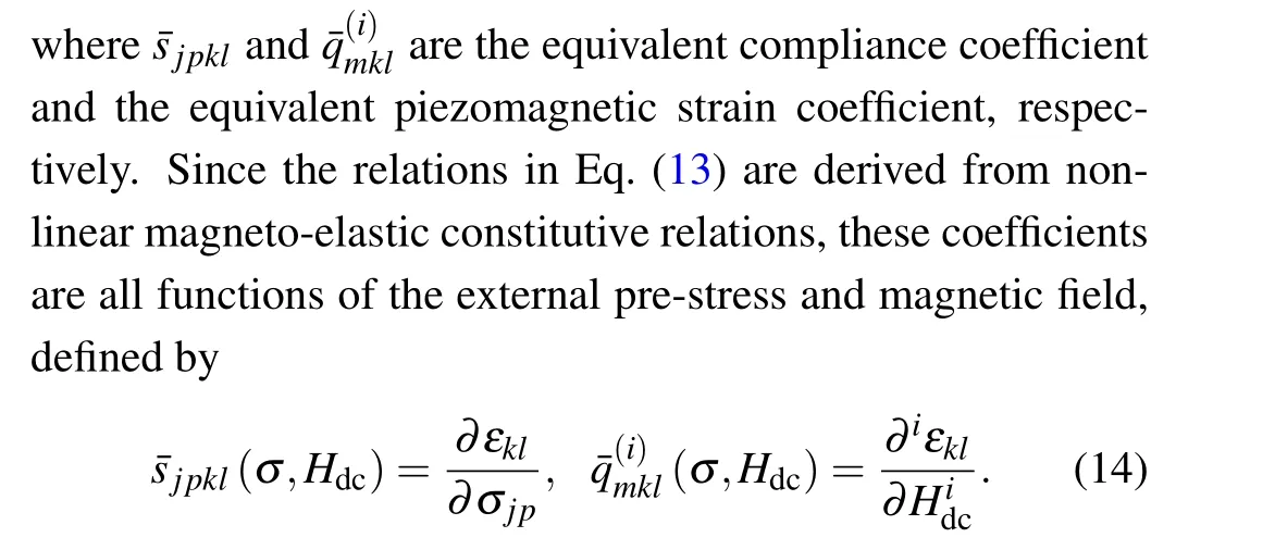

Note here that the above linear-like form is fully magnetoelastic coupled since all the material parameters are strictly derived from the nonlinear magneto-elastic coupling constitutive relations. In order to unify the nonlinear and linear relations in form,the relation in Eq.(14)can be rearranged as

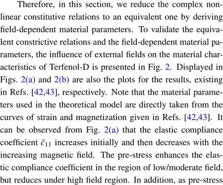


Fig.2. (a)Elastic compliance coefficient and(b)piezomagnetic coefficient of Terfenol-D versus magnetic field under different pre-stresses.
4. Results and discussions
In this section, numerical calculations are performed for the ring-shaped composites and some significant predictions are presented based on our model. The piezoelectric material is chosen as BaTiO3, and the magnetostrictive materials for linear and nonlinear cases are chosen as CoFe2O4and Terfenol-D, respectively. The material parameters used for numerical calculations are listed in Tables 3 and 4.[44,45]The volume fraction of the piezoelectric phase is defined byv=(c−b)/(c−a). The inner and outer radii of the ring are fixed ata=9 mm andc=13 mm, respectively. The ac field isHac=1 Oe, the resistance isRl=50 kΩ, and the volume fraction isv=0.5. For studying the resonance ME coupling,a damping coefficientχis used to describe resonance loss.The damping coefficient is determined byχ=1/Q=∆f/fr,whereQis the quality factor for the observed resonance,fris resonance frequency,and ∆fis the bandwidth. Wanet al.[15]experimentally obtained the effective quality factor of~48 for the first bending resonance and~51 for the first longitudinal resonance, indicatingχ=0.02 may be believable in numerical calculation. Zhanget al.[46]and Zhaoet al.[47]also usedχ=0.02 to evaluate the resonance ME effects in multiferroic laminates plates and cylinders. In the current study,ω′=(1+0.02i)ωis taken into account in the numerical calculation.

Table 3. Material parameters of BaTiO3 and CoFe2O4.
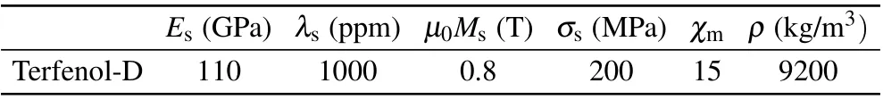
Table 4. Material parameters of Terfenol-D.
4.1. Model degeneration and validation
It is noteworthy that the theoretical model in the above sections is established for ring-shaped structures,which,however, can be degenerated into the model for disk/ring structures. In the configurations of disk/ring structures, a piezoelectric disk is inserted into a magnetostrictive ring (denoted by P/M),or a magnetostrictive disk is inserted into a piezoelectric ring(denoted by M/P).Unlike the ring-shaped structures,the inner radiusaof the disk/ring structures is set to be zero,and the displacement at the center of disk should not be infinite,i.e.,one of the undetermined coefficients in Eq.(5)must be zero. Recently, the dynamic ME response of a Terfenol-D disk/PZT ring has been well reported experimentally by Li and Chen.[48]Here, we compare the predicted ME effects of Terfenol-D disk/PZT ring with experimental data in Ref.[48],and plot the open-circuit ME coefficient as a function of the driving frequency in Fig.3. Note that for the results presented in Fig.3,the inner diameter,the outer diameter,and the thickness are 10 mm,12 mm,and 0.95 mm,respectively. It may be observed that the proposed scheme is able to capture both the maximum ME coefficient and the resonance frequency. The two sets of results are in very close agreement,indicating that the theoretical model is sufficiently accurate for characterization of dynamic ME effect.
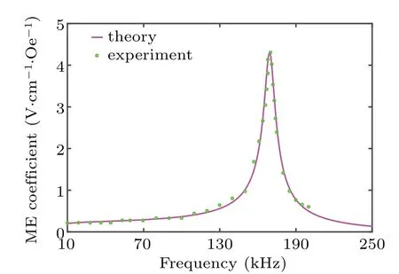
Fig. 3. ME coefficient of Terfenol-D disk/PZT ring with varying the driving frequency.
4.2. Regulation mechanism via mechanical boundary conditions
The results presented in Fig. 4 report the ME voltage of ring-shaped energy harvester versus the driving frequency of magnetic field for both conventional and stress boundary conditions listed in Tables 1 and 2. The results for conventional boundary conditions are calculated by setting the applied stressP0in Eq. (9) to zero. Since the type of boundary conditions dictates the distribution of displacement field throughout the composite,the induced ME voltages under different boundary conditions change variously. For some of the conventional boundary conditions (i.e., F-F, F-C, and CF),two obvious resonance frequencies are obtained within the range of 0–1400 kHz,as shown in Fig.4(a). In addition,setting a stress-free condition makes it easy to induce a resonance response at low frequency, while setting a clamped condition is beneficial for tuning a larger resonance frequency. Thus,the condition F-F corresponds to the lowest resonance frequency,whereas the condition C-C to the largest one. Except for the type of boundary condition, the location at which a specific condition is applied may affect the transfer of displacement from one layer to the other, and therefore matters. It can be found that setting the outer boundary stress-free may result in notable ME coupling at a lower frequency. For example,the maximum ME voltages for F-F and C-F conditions are achieved at the fundamental frequency, while the F-C condition shows notable ME voltage at the second-order frequency.The expression in Eq.(9)indicates that ME voltage is significantly related to the displacements at the outer boundaryr=cand the interfacer=b. Thus,the effect of boundary condition on ME coupling is twofold. First, the type of boundary condition changes the radial displacement at the outer boundary.For example, the conditions F-C and C-C dictate a zero displacement at the outer boundary. Second,the solutions of the undetermined coefficients in Eq.(9),determined by the values and types of boundary conditions,will indirectly affect the displacement at the interface through the solutions of two Bessel differential equations. Based on these mechanisms, ME performance of the proposed ring-shaped energy harvester may be tuned by optimizing the prescribed value of the displacement on the boundaries.
In the current theory,when the stress boundary conditions are applied,the only operation is to replace the zero stress by a nonzero one for a boundary. In other words, relaxing the conditions S-F or F-S from applied stress to stress-free results in the condition F-F. Similarly, the corresponding stress-free condition for S-C and C-S are F-C and C-F,respectively.Comparing Figs.4(a)and 4(b),we find that applying stress can improve ME voltage,without changing the resonance frequency of the corresponding conditions. The peak ME voltages and resonance frequencies under different boundary conditions are summarized in Fig.5. As can be seen, the peak ME voltages under conventional boundary conditions are significantly enhanced by applying stress at the free boundary. For example,the peak ME voltage under the condition F-F is increased from 0.63 to 1.80 V after applying a 6-kPa stress at the outer boundary. In essence, piezoelectric effect is improved by the additional mechanical strain when at least one of boundaries is subjected to applied stress,resulting in the enhanced output voltage.
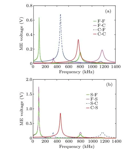
Fig.4. ME voltage of ring-shaped energy harvester versus the driving frequency of magnetic field for(a)conventional and(b)stress boundary conditions(P0=6 kPa).
Figure 6 shows the ME voltage versus the driving frequency with varying the applied stress under different boundary conditions. For all the stress boundary conditions,the results with a zero stress reduce to those for the corresponding conventional conditions. It can be seen that as the stress increases,ME voltage is improved continually,demonstrating a monotonically increase. However, it should be noted that in actual operation the applied stress may be properly increased,always assuming that its valueP0should not exceed the allowable stress[σ]of constituent materials. The present model shows that the effect of stress boundary conditions on ME coupling is also twofold. First, once a stress is applied at inner or outer free boundary,it influences the solutions of displacement in Eq.(5)by changing the values of undetermined coefficientsAiandBi,In other words,stress boundary condition will change the strain distributions in the composites,and thus may improve both piezoelectric and piezomagnetic effects. Second,the applied stress increases the second term in the numerator of Eq. (9), and thereby additional voltage is directly obtained via the improved piezoelectric effect. Equation(9)also suggests that ME performance can be enhanced,only with the displacement related to stress boundary condition being of the same sign as that related to the applied magnetic field. This provides a theoretical guidance for a specific operation.
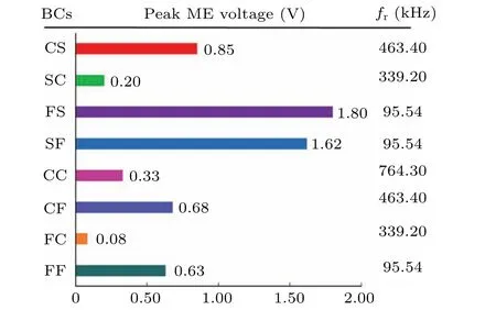
Fig. 5. Maximum ME voltages and the corresponding response frequencies under different boundary conditions(P0=6 kPa).
Figure 7 shows the output power density versus resistance under different boundary conditions. For any boundary condition, a maximum power density is obtained at an optimal resistanceRo. The optimal resistances are different for different conventional conditions. As is expected,peak power densities for conventional conditions F-F,F-C,and C-F are enhanced by applying stress at the original stress-free boundaries. Interestingly,but not surprisingly,the optimal resistance is unchanged after setting the applied stress. The peak power densities,and the corresponding optimal resistances and resonance frequencies are summarized in Fig. 8. The C-C boundary condition,being the one that sets the displacements at both boundaries to zero,may give rise to the stress built up in the composite,and thus exhibits notable ME performance. In addition,when the composite is constrained at least on one side, the optimal resistance appears to be reduced and the resonance frequency be increased. Consequently,ME harvester under the C-C boundary condition exhibits the maximum power density with the minimum optimal resistance and highest resonance frequency.In comparison, a remarkable fact is that the C-S boundary condition reduces the resonance frequency for the C-C boundary condition by about 40%with almost unchanging the peak power density at a larger optimal resistanceRo=15 kΩ.In all,there is still much room for improvement in ME performance since the applied stress in Fig.8 is only 6 kPa,which is far less than the allowable stress of constituent materials.

Fig.6. ME voltage versus the driving frequency for different boundary conditions: (a)C-S,(b)S-C,(c)F-S,and(d)S-F.

Fig.7. Output power density versus resistance for different boundary conditions: (a)C-S,(b)S-C,(c)F-S,and(d)S-F.
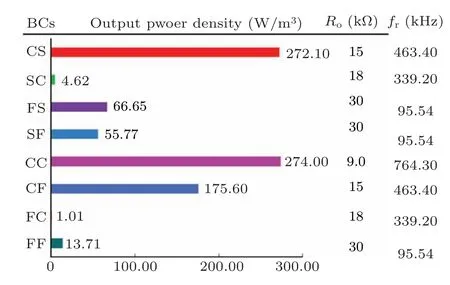
Fig.8.Maximum power densities and the corresponding optimal resistances for different boundary conditions(P0=6 kPa).
4.3. Regulation mechanism via multi-field stimuli
In this section, we intend to study the nonlinear multifiled coupled mechanisms of ME energy harvester and tune ME performance via external stimuli. Experiments have demonstrated that a typical giant magnetostrictive material Terfenol-D exhibits strong magnetostrictive effect and complex nonlinear coupling characteristics when it is subjected to combined stress and magnetic loadings. Therefore, we select Terfenol-D as the magnetostrictive phase of the ringshaped composites and expect to obtain some novel phenomena. The material parameters used for numerical calculations are listed in Table 4. Unless otherwise mentioned,the applied pre-stress is fixed atσ0=−10 MPa. Figure 9 displays the ME voltage versus the applied bias magnetic field for different frequencies. Note that the results presented in Fig. 8(a)include ME voltages of Terfenol-D/BaTiO3using nonlinear model and CoFe2O4/BaTiO3using linear model. It can be seen that the ME voltage predicted from linear model is independent of the applied bias field at any frequency. However,when the nonlinear multi-field coupling of Terfenol-D is taken into account in the nonlinear model,an interesting phenomenon happens. That is, the ME voltage firstly increases and then decreases with bias magnetic field, indicating that an optimal bias field may be used to tune ME performance of the ring-shaped composites. This highlights the second novelty of this study while accounting for active control of ME energy harvesters. Generally, ME composites need to be operated at an external bias magnetic field for available ME response since piezomagnetic effect vanishes at zero field. This,however,inevitably increases the excess energy consumption.Most of the conventional ME composites used a pair of electromagnets to produce bias magnetic fields,because it is convenient to adjust the magnitude of bias field. However, the electromagnets may cause an increase in the complexity of the device and a compromise in the performance. In the current study we present a simple and effective way to design a self-biased ME energy harvester. Four pieces of plate-shaped NdFeB magnets are arranged in the 0°, 90°, 180°, and 270°directions in a ring-shaped aluminum mold cavity of dimensions the same as the magnetostrictive ring so as to create a bias magnetic field. With the NdFeB magnets in place, the Terfenol-D short fibers are aligned and then the epoxy is transferred into the mold. Therefore, a magnetically biased magnetostrictive composite ring is successfully fabricated. Based on the proposed nonlinear theoretical model,the optimal bias fields for different application scenarios can be accurately predicted in advance. Then,the precise static magnetic field may be produced by choosing NdFeB magnets with proper dimensions.It can be seen from Fig.9(a)that at comparatively lower frequencies only one peak appears in the ME voltage versus bias field curve of Terfenol-D/BaTiO3. As the frequency increases, the peak position moves slightly toward higher bias field, and the ME coupling effect is enhanced considerably.According to the interfacial conditions in Eq.(6),the termuHin Eq.(7)is proportional to(equivalent)piezomagnetic coefficient. Thus, we can deduce from Eq. (7) that ME voltage should be also proportional to the(equivalent)piezomagnetic coefficient. The solutions for nonlinear material parameters in section 3.4 show that the equivalent piezomagnetic coefficient depends strongly on the applied bias field. That is why ME voltage is markedly affected by the bias field. Essentially,the peak position of ME voltage corresponds to the optimal bias filedHoptat which the maximum value of the equivalent piezomagnetic coefficient of Terfenol-D occurs. Figure 9(a)also indicates that low frequency has a slight effect on theHopt. At frequencies from 400 to 430 kHz, the curve of ME coefficient varying with bias field exhibits a dual-peak phenomenon,namely,two peaks appear with the increase of bias field. A similar dual-peak phenomenon was recently experimentally observed in laminated ME composites by Zhaoet al.[49]and our group.[50]With increasing the frequency, the first peak moves toward lower bias field while the second one toward higher bias field. For example,the first peak appears at 216 Oe forf=400 kHz,and 76 Oe forf=430 kHz,respectively; the second peak appears at 560 Oe forf=400 kHz,and 896 Oe forf=430 kHz,respectively. At the same time,both the first and second peaks are reduced by increasing frequency. Since the dual-peak phenomenon appears at larger frequency and the optimal field corresponding the second peak is changed, we deduce that the origin and mechanism of this phenomenon may be related to both the frequency of ac field and the magnitude of bias field. To validate this, ME voltage versus the driving frequency is plotted in Fig.10,with the bias field being set at previously specified ones,i.e.,560,680,788,and 896 Oe, which are the values of the optimal fields at frequencies of 400, 410, 420, and 430 kHz, respectively. When the bias field is fixed, the ME voltage maximizes at a certain frequency due to the mechanical resonance of the ring-shaped composites under ac magnetic field. This indicates a one-toone correspondence between the resonance frequency and the bias field we call it the required field. It should be noted that the resonance frequency and the required field in Fig. 10 coincide exactly with those in Fig.9(b). Meanwhile,the second peak of ME voltage in Fig.9(b)at a fixed bias field are exactly the same as the peak ME voltage in Fig. 10 at the same bias field. Therefore,it has been proved that the occurrence of the second peak is caused by the resonance under a certain value of magnetic field. Equation (16) reveals that variation of the equivalent elastic coefficient with external bias field,known as∆Eeffect,[51,52]may lead to the resonance frequency change with the bias field. That is why the peak ME voltage and the resonance frequency in Fig. 10 changes with the bias field.Based on this mechanism,a much broader range of resonance frequencies is expected to be achieved.

Fig.9. ME voltage versus the applied bias magnetic field for different frequencies:(a)100,130,160,and 190 kHz,and(b)400,410,420,and 430 kHz(σ0=−10 MPa).

Fig. 10. ME voltage versus the driving frequency at a bias magnetic field of 560,680,788,and 896 Oe.
Figure 11 displays the ME voltage versus the applied bias magnetic field for different pre-stresses. As pre-stress increases,the first peak increases with the optimal field moving slightly toward right, while the second peak reduces with the required field moving toward right. Thereby, available ME coupling may be realized within a wide bias field. By way of example,the ME voltage withσ0=−10 MPa reaches 70%of the second peak when the bias field is in the range from 156 to 560 Oe. The variation of the optimal(required)fields and the peaks are plotted in Fig. 12. It can be seen that each keeps a linear relation with the external pre-stress,offering much convenience for tuning ME performance of the proposed energy harvester.

Fig.11. ME voltage versus the applied bias magnetic field for different pre-stresses(f =400 kHz).
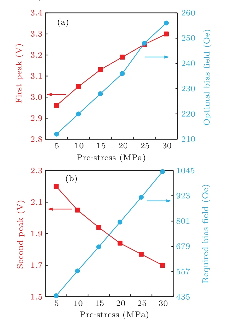
Fig.12. The peak values and the corresponding optimal bias fields versus pre-stress:(a)the first peak,and(b)the second peak(f =400 kHz).
Lastly,we study the effects of pre-stress on the resonance of the composites. Figure 13 shows the ME voltage versus the driving frequency for different pre-stresses. At a lower bias field(100 Oe),ME voltage is enhanced by increasing tensile stress, with the resonance frequency being reduced. On the contrary,the ME voltage is weakened by increasing compressive stress,with the resonance frequency being increased.However,at a high bias field(500 Oe),the ME voltage is improved via reducing tensile stress or increasing compressive stress, with the resonance frequency being reduced. This indicates that a critical bias field may occur, below and above which the effects of pre-stress on the peak ME voltage and the resonance frequency are completely opposite. This critical bias field is actually the same as the optimal field corresponding to extreme point of the equivalent coefficient of Terfenol-D.

Fig. 13. ME voltage versus the driving frequency for different prestresses: (a)Hdc=100 Oe,and(b)Hdc=500 Oe.
Figure 14 shows the contour plots of the peakME v oltage and resonance frequency as functions of pre-stress and bias field. The results presented further validate the different change laws of peak ME voltage and resonance frequency with the pre-stress at different bias magnetic fields. When the bias field is lower than 200 Oe,the peak ME voltage is reduced as pre-stress increases from−60 to 0 MPa. However, a nonmonotone variation is observed when the bias field exceeds 200 Oe. As a consequence, the maximum peak occurs in the region of (−30 MPa<σ0<−20 MPa,Hdc>240 Oe). Figure 14(b)indicates that a broad range of resonance frequencies is obtained to be 385–425 kHz by coordinately control external pre-stress and magnetic stimuli.It is expected that the range of resonance frequencies can be further broadened by adjusting bias magnetic field. The critical bias filed for resonance frequency is about 275 Oe,below which the latter monotonically increases with pre-stress, or above which firstly reduces and then increases. Therefore, the predicted nonlinear behaviors under external stimuli build a new theoretical mechanism for tunable control of ME energy harvesters.

Fig.14. Contour plots of(a)the peak ME voltage and(b)the resonance frequency as functions of pre-stress and bias field.
5. Conclusions
In summary, we have proposed a theoretical model for studying ME coupling of energy harvesters using ring-shaped composites, with introducing a new type of boundary conditions as well as considering the multi-field coupled material’s properties. This model can be applied to predict output ME voltage, resonance frequency and power density of applications including energy harvesting and sensing under external stimuli. By utilizing the theoretical model, some important conclusions can be drawn as follows:
(1)Setting a stress-free condition at any boundary is beneficial for inducing mechanical resonance,and thereby the F-F boundary condition corresponds to the lowest resonance frequency and more harmonics within the range of frequencies(0–1400 kHz)investigated.
(2)Clamped conditions on the inner and outer boundaries may give rise to the stress built up in the composite,and thus improve the maximum power density. Once the composite is constrained at least on one side,the optimal resistance reduces and the resonance frequency increases.
(3)Stress boundary conditions strengthen strain distribution, and enhance ME coupling significantly, without changing the corresponding resonance frequency and optimal resistance. The applied stress in actual operation may be properly increased on the premise that its valuePshould not exceed the allowable stresses of constituent materials.
(4) A theoretically revealed dual-peak phenomenon around resonance frequencies demonstrates the occurrence of two optimal bias fields corresponding to the strong ME coupling. The linear relation between pre-stress and the optimal bias field offering much convenience for tuning ME performance within a wide field range.
(5) The peak ME voltage is increased from 1.4 to 3.2 V with applying proper pre-stress and bias field. A broad range of resonance frequencies can be obtained from 385 to 425 kHz by tuning pre-stress from 0 to 60 MPa and bias field from 100 to 400 Oe. It is expected that the mutual coordination of the applied bias magnetic field and pre-stress promotes commonly the improvement of ME performance.
The present theoretical model provides more options for optimizing ME performance of ring-shaped composites via mechanical and magnetic conditions. Nonlinear coupling properties revealed in this paper may result in an emerging revolution for tunable, active, or even smart control of ME harvesters. In addition,the current modeling idea may be applied to solve nonlinear multi-field coupling problem of other smart materials and structures.
猜你喜欢
杂志排行

Chinese Physics B的其它文章
- Physical properties of relativistic electron beam during long-range propagation in space plasma environment∗
- High winding number of topological phase in non-unitary periodic quantum walk∗
- Widely tunable single-photon source with high spectral-purity from telecom wavelength to mid-infrared wavelength based on MgO:PPLN∗
- Control of firing activities in thermosensitive neuron by activating excitatory autapse∗
- Adaptive synchronization of chaotic systems with less measurement and actuation∗
- Dynamics analysis of a 5-dimensional hyperchaotic system with conservative flows under perturbation∗