An integration method based on a novel combined flow for aerodynamic configuration of strutjet engine
2021-10-27LongshengXUEChuanCHENGChengpengWANGKemingCHENG
Longsheng XUE, Chuan CHENG, Chengpeng WANG,*, Keming CHENG
a College of Aerospace Engineering, Nanjing University of Aeronautics and Astronautics, Nanjing 210016, China
b Key Laboratory of Unsteady Aerodynamics and Flow Control, Ministry of Industry and Information Technology,Nanjing University of Aeronautics and Astronautics, Nanjing 210016, China
c Aerospace System Engineering Shanghai, Shanghai 201100, China
KEYWORDS Airframe-propulsion integration;Busemann flow;Combined flow;Hypersonics;Wind tunnel test
Abstract In this paper a novel design method of aerodynamic configuration is proposed to integrate forebody, strut and inlet for strutjet engine, and a model at design point of Mach number 6 is generated to investigate the aerodynamic performance by both simulations and experiments.The basic flow field employed by proposed method is a combined flow named IBB, which is combined by Internal Conical Flow A(ICFA),truncated Busemann flow I(BI)for external section,and truncated Busemann flow II (BII) for internal section. The model configuration is generated by streamline tracing method from basic flow field,in which the forebody section is traced from ICFA and BI flows,and the inlet as well as strut section is traced from BII flow.The simulations in Mach number 4, 5, and 6 demonstrate uniform starting flow fields with relatively high total pressure recovery, which agree well with experiments in wind tunnel. Additionally, in low Mach number cases, this inlet could start at Mach number 3 while it is unstarted at Mach number 2.7; in high Mach number cases, a uniform flow could still exist in Mach number 6.5 while a relatively strong shock wave boundary layer interaction is found in cowl area of Mach number 7 case,indicating the inlet designed by proposed method works in a relatively wide Mach number range.
1. Introduction
The airbreathing hypersonic vehicle utilizing Rocket Based Combined Cycle propulsion (RBCC) is a promising future technology for earth/orbit transportation system,which provides the capabilities for ground-takeoff and reusability due to its low cost and high performance at wide range of flight height and speed. The strutjet engine,one of the concepts of RBCC propulsion, operates in both subsonic mode of ramjet and supersonic mode of scramjet in a single flow path,demanding a proper integration methodto achieve high aerodynamic performance for forebody, strut and inlet.
A design of aerodynamic configuration for forebody or inlet usually chooses one or several performances as main design orientation,resulting in various methods for different applications.On one hand, the forebody, which generates the main lift for hypersonic vehicle, should induce a leading shock and steady subsequent shock waves for the overall flow field; on the other hand, the inlet, which provides a steady stream of compressed air to the combustion chamber, has to meet the strict requirement of sufficient compression and low aerodynamic loss.The current study focuses on the streamline traced configurationfor inlet and vehicle integration design,which depends on an excellent basic flow. The aerodynamic loss,normally represented by total pressure loss,is mostly produced by shock waves and boundary layer,thus basic flows with high total pressure recovery are very suitable to be employed to design inlet.Moelder and Szpiroproposed a method based on an axisymmetric internal flow, known as Busemann flow, to design hypersonic inlet for reducing aerodynamic losses. Busemann flow field consists of a long isentropic-compression section with a series of weak waves and a downstream conical shock, which provides a uniform outlet flow paralleling to the freestream. Additionally, Busemann flow field is characterized by a small total pressure loss of shock wave but a large loss of boundary layer. The performances of Busemann flow field had shed new light on inlet design,based on which various investigations and applications of novel methodshave been conducted theoretically,numerically and experimentally.The long compression section produces the main losses in Busemann flow field, which could be improved by truncated Busemann flow.However, the truncated leading edge damages the original compression waves, resulting in a nonuniform outlet flow and downstream shock reflections,which degrades inlet performance distinctly.You,et al.attempted to improve the truncated Busemann flow by combining flows,e.g.a combined flow consisted of Internal Conical Flow A (ICFA) and truncated Busemann flow, named ICFC flow or ICFD flow depending on two connection methods, could achieve a better performance than direct truncated Busemann flow. The ICFA flow provides a steady incoming flow for truncated Busemann flow.ICFA flow and truncated Busemann flow could be connected each other by keeping successive Mach number (ICFC flow) or keeping a same flow direction (ICFD flow), in which ICFC flow was found performing better.
A hypersonic inlet might lose performance by embedding it into the forebody, similarly, the performance of a well designed forebody might be decreased by assembling a sophisticated inlet,which means the losses of forebody and inlet should be avoided via proper integration design as a whole.The inlet in integration methods should be designed based on the basic flow field generated by forebody, e.g. a concept coupling waverider forebody with Busemann inlet,or a concept of dual waverider.The struts in strutjet engine could employ three-dimensional compression to decrease forebody turning requirements and reduce inlet losses.For parallel modular strutjet engine,the freestream is compressed firstly by forebody, then the inlets and struts provide additional compression,meaning the forebody,strut and inlet should be generated by integration to lessen flow interaction and aerodynamic losses.
Based on the analyses of conical flows as well as combined flow, the current study proposes an integration method to design forebody, strut and inlet for strutjet engine, in which the basic flow is combined by ICFA,truncated Busemann flow I for external section, and truncated Busemann flow II for internal section. Additionally, a three dimensional inwardturning inlet with forebody is designed to validate this method,of which the main design points include free stream Mach number Ma=6, outlet Mach number Ma=3, total contraction ratio CR=5, internal contraction ratio CR=2,leading edge angle of forebody α=6°, and Mach number of inlet start ranges from 4 to 6. The performances of the inlet are presented by both simulations on various Mach numbers ranging from 2.7 to 7 and experiments in wind tunnel on Mach numbers of 4, 5 and 6.
2. Basic flow generation
2.1. Axisymmetric conical flow
A uniform compressed flow with little total pressure loss is normally generated by weak shock waves and few shock wave interactions. The length of a conical flow path is usually shorter than a two-dimensional flow for generating a same compression. Assume that a conical flow field with all the shock waves interacting on one point to compress freestream gradually, this flow obeys a flow motion equation named Taylor-Maccoll equation.There are four axisymmetric conical flows obeying Taylor-Maccoll equation, which had been summarized by Moelderas shown in Fig. 1, including (A)external conical flow,(B)Busemann flow,(C)Internal Conical Flow A (ICFA) and (D) Internal Conical Flow B (ICFB).These conical flows consist of a series of weak waves and a conical shock,inducing a uniform flow for downstream outlet,while only Busemann flow and ICFA flow are suitable for inlet design.
Taylor-Maccoll equation is defined in polar coordinates,which is derived as follows:

Additionally, the differential equation of polar radius r is given by:
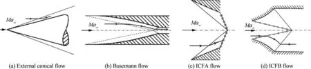
Fig. 1 Possible axisymmetric conical flows obeying Taylor-Maccoll equation.

which means a singularity exists in u=a. On one hand, if iterations are solved from upstream conditions to the singularity, the flow will be generated as ICFA flow shown in Fig. 2(a); on the other hand, if iterations are solved from downstream conditions to the singularity,the flow will be generated as Busemann flow shown in Fig. 2 (b).
Busemann flow field is characterized by a long isentropic compression section followed by a conical shock, in which the three-dimensional Mach contours as well as Mach contours on symmetry are shown in Fig. 3 (an example for Ma=6 and Ma=3).The overall Busemann flow,as indicated in Fig. 3, shows outstanding performances involve: (A)the compression of freestream starts from a weak wave, and subsequent flow is invariant to r and is only related to θ; (B)all the compression waves interact on one point, and are cancelled by a downstream conical shock;(C)downstream flow of outlet paralleling to freestream is very uniform; (D) both freestream Mach number and outlet Mach number can be free designed for various applications.
A Contraction Ratio (CR)is defined as captured flow area size divided by outlet flow area size, and the main performances of Ma=6 Busemann flow changed by CR are shown in Fig. 4. For the three variables: freestream Mach number Ma, outlet Mach number Maand contraction ratio CR,any two of them determine a single Busemann flow configuration. As is depicted in Fig. 4, the inviscid Busemann flow shows relatively high total pressure recovery and pressure rise for various Mach numbers of outlet, however, the length of compression section grows fast with the increasing of CR,which means the total pressure loss of boundary layer would be very serious. Additionally, the leading edge of Busemann flow configuration is very sharp, which would result in problems of structural strength and aerodynamic heating.Therefore, Busemann flow is not suitable to be employed to design hypersonic inlet directly.
2.2. Combined flow
Truncated Busemann flow,which is truncated at a position with a given flow deflection angle, is one of the effective improvement methods to lessen disadvantages of overall Busemann flow. As shown in Fig. 5 (a), the flow boundary is truncated at the position of flow deflection angle of 3°, which approximately shortens the original flow field 30% in length.However, the leading weak wave is replaced by an incident shock due to a 3° flow deflection angle, which damages the subsequent compression waves.The incident shock interacting with weak waves is curved,and the downstream conical shock cannot be cancelled,resulting in downstream shock reflections and a nonuniform outlet flow.
Because ICFA flow has a straight incident shock and a very short isentropic compression section,You et al.attempted to combine ICFA and truncated Busemann for improvement.However,the downstream Mach number Maand flow deflection angle αof ICFA cannot be equal to Maand αof truncated Busemann simultaneously at the truncated position,which means it is impossible to connect each other perfectly.There are consequently two connection methods at the truncated position:one is named ICFC flow under the conditions of α≠αand Ma=Ma,the other is ICFD flow with α=-αand Ma≠Ma.

Fig. 2 Sketch of flows solved by different iteration methods.
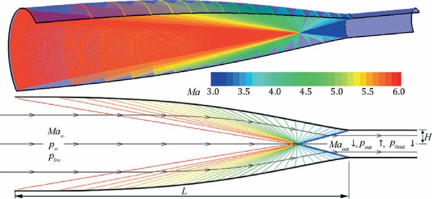
Fig. 3 Mach contours of inviscid Busemann flow field for Ma∞=6 and Maout=3.

Fig. 4 Performances of inviscid Busemann flow for Ma∞=6 with various contraction ratios.

Fig. 5 Mach contours of different inviscid flows and comparison of lengths.
As is indicated in Fig. 5 (b), the ICFC flow starts from a straight incident shock, inducing weak waves for truncated Busemann section, followed by a series of compression waves interacted nearly on one point,and outlet flow is more uniform than direct truncated Busemann flow. Fig. 5 (c) gives the flow configuration of ICFD, in which a line section is used to connect ICFA and truncated Busemann to keep a same flow deflection angle. Due to the discontinuity of Mach number, it is hard for compression waves to interact on one point,resulting in a less uniform outlet flow than ICFC, which means the continuity of Mach number is more important than flow deflection angle. The comparison of compression lengths in flows of overall Busemann, truncated Busemann, ICFC and ICFD are shown in Fig. 5. (d), which are generated under the same conditions of freestream Mach number,outlet Mach number and outlet height. It can be observed that truncated Busemann,ICFC and ICFD are distinctly shorter than overall Busemann, and ICFC is more suitable to be employed to design inward turning inlet due to its better performance.
3. Proposed method for integration design
3.1. Novel combined flow
The forebody of a hypersonic vehicle, e.g. waverider,produces the main lift force, and also induces a leading shock for inlet,which could be employed as pre-compression via integration design method. For strutjet engineof RBCC propulsion, the struts provide three-dimensional compression, which could also be employed as additional compression for inlet.Therefore, in proposed method, forebody is considered as a top wall of inlet, and struts are treated as side walls of inlet.According to the analyses of various basic flows mentioned above,the current study proposes a design method for integration of forebody, strut and inlet, which is based on a novel combined flow named IBB.
IBB flow consists of ICFA(section I),truncated Busemann I (section BI) and truncated Busemann II (section BII), as shown in Fig. 6. The external compression section for forebody contains section I and BI,of which the connection is similar to ICFC. The internal compression section for inlet and struts is BII, which is connected to BI by both successive flow deflection angle and Mach number, while BI and BII are generated respectively from two center points, oan o, as shown in Fig. 6.
There are six independent control variables of IBB flow including: freestream Mach number Ma, outlet Mach number Ma, the leading edge angle α of forebody (or leading shock angle β),total contraction ratio CR,internal contraction ratio CR(or external contraction ratio CR),and the leading edge angle θof strut (or outlet flow deflection angle θ). IBB flow is generated by the steps as follows:
(1) Solve ICFA flow of section I by iterations under the upstream boundary conditions of Maand α, and determine downstream parameters of section I including: Mach number Ma, polar angle θ, contraction ratio CR.
(2) Solve truncated Busemann flow of BII by iterations under the downstream boundary condition of Maand control variables of CRand θ, and determine upstream Mach number Maof section BII.
(3) Determine contraction ratio CRof section BI under the control variables of CR, CR, and CR(or CR),which is given by CR=CR/(CR∙CR).
(4) Solve truncated Busemann flow of BI by iterations under the upstream boundary conditions of Maand θ, downstream boundary condition of Maand control variable of CR, and determine the downstream flow deflection angle θof section BI.
(5) Connect I and BI at point A,and connect BI and BII at point B.
(6) Rotate BII clockwise around point B with an angle of θ,which is given by θ=θ-θ.
(7) At last,zoom BII around point B to make sure that line l, which is determined by center points of oand o, is parallel to line l, which is a tangent line at point B.
3.2. Streamline traced configuration
The boundary configuration of basic flow field cannot be employed as wall surface of inlet directly due to the difficulty of assembling and the problem of inlet selt-starting.A flow tube with a particular appearance of inlet or outlet is normally employed as final configuration of inlet design,which is shaped by streamline tracing methodfrom the basic flow field.The streamline traced inlet could inherit the major performances of basic flow after boundary layer correction, and the profile is very flexible, which can be any shape for various applications, as shown in Fig. 7 (three examples for rectangular, circular and fanlike inlets, which are streamline traced from a Busemann flow).The inlet configuration can be streamline traced from upstream to downstream based on discrete spots of inlet profile,and it also can be streamline traced from downstream to upstream based on discrete spots of outlet profile, depending on integration method.
The current integrated configuration couples the streamline traced forebody, strut and inlet, which are conducted in two steps. Because the proposed method applies to multi parallel modules of strutjet engine(Fig.8),the rectangular outlets are suitable for assembling struts,of which the aspect ratio is determined by the size of struts.As shown in Fig.9,the generation of a single module starts from a rectangular outlet:firstly,the inlet is streamline traced from outlet to upstream leading edges in BII flow,containing four surfaces,in which side walls are treated as two struts, and the bottom leading edge is regarded as a seam between BI and BII; secondly, the forebody wall is streamline traced from the seam to upstream leading edge in BI and I flows,which contains only one surface.It should be noted that a cowl in the shape of‘‘V”is formed as a spillage windowin the roof.

Fig. 6 Sketch of IBB flow configuration.

Fig. 7 Examples of streamline traced inlets with various shapes.

Fig. 8 Single module to multi parallel modules for strutjet engine.
Additional processes are necessary for generating multi parallel modules.As shown in Fig.8,firstly,the two sides of I and BI in a single module should be trimmed parallel,of which the width is equal to the width of inlet; secondly, BII should be extended downstream to connect to a section of isolator; at last, several single modules lay out side by side to form multi parallel modules. For validating the proposed method, an example is designed under the main design points including free stream Mach number Ma=6, outlet Mach number Ma=3, total contraction ratio CR=5, internal contraction ratio CR=2, leading edge angle of forebody α=6°.The final designed configuration after the processes shown in Fig. 8 is characterized by CR=5.095, CR=2.071, and α=6°,of which the aerodynamic performances under various Mach numbers are presented by both experiments and simulations in following sections.
4. Aerodynamic performance analysis
4.1. Test model and numerical methods

Fig. 9 Streamline traced configuration for integration of forebody, inlet and struts.
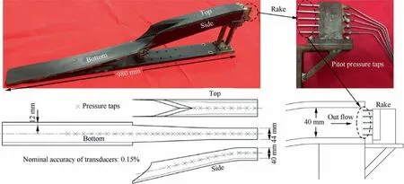
Fig. 10 Test model and pressure taps.
The starting flow field of Mach number ranging from 4 to 6(the test model of single module is designed at Mach number 6 as shown in Fig. 10) is very important for scramjet mode,which demands high aerodynamic performances. Therefore,the current experiments were conducted under Mach number 4,5,and 6 in the Hypersonic Wind tunnel of Nanjing University of Aeronautics and Astronautics (NHW), of which the experimental apparatus and measurements have been well described in previous studies.The test model with a 980 mm length and a 40×44 mmoutlet area is shown in Fig. 10, and the model is put upside down due to the fixture in test section.Because of the strong relation between shock structure and wall pressure,schlieren is employed and there are 9,28,and 12 pressure taps,sampled by fast-response transducers (nominal accuracy: 0.15%) with 1 kHz, distributed along central lines on top, bottom, and one side walls, respectively. Additionally, a rake with 5 pitot pressure taps is mounted downstream the outlet.
For a clearer understanding to the overall flow field, it is necessary to conduct numerical simulations by a threedimensional Navier–Stokes solver. The k-ω Shear Stress Transport model (SST), of which the validity for applying to hypersonic inlet flow field was verified by the study of Wang et al.as well as a similar work by Huang et al., is employed to model the turbulent flow,and the governing equations are discretized by a second-order upwind scheme.Additionally,the near-wall region flow is modeled by the standard wall functions.
A fine structural grid with y+≈1 containing 1.4×10nodes is generated for the simulation, of which the grid sensitivity has been analyzed in previous study.The settings of computational domains, including pressure far field, symmetry, pressure outlet and wall, are shown in Fig. 11, in which the overall flow field is divided into three blocks. In addition,the grid near shock location and boundary is refined to dense grid.More details of the boundary conditions equivalent to the experimental conditions are listed in Table 1.
4.2. Results and analysis
The comparisons between experimental and numerical results of Mach number 6, 5, and 4 are summarized in Figs. 12–14,respectively, in which all the pressures are normalized by freestream conditions.The pressure distributions on top,side,and bottom obtained by pressure taps agree well with numerical pressure lines, as shown in Fig. 12(a), 13(a), and 14(a). Additionally, the pressure distributions of outlet, represented by pitot pressure pshown in Fig. 12(b), 13(b), and 14(b), also demonstrate good agreements between experiments and simulations.
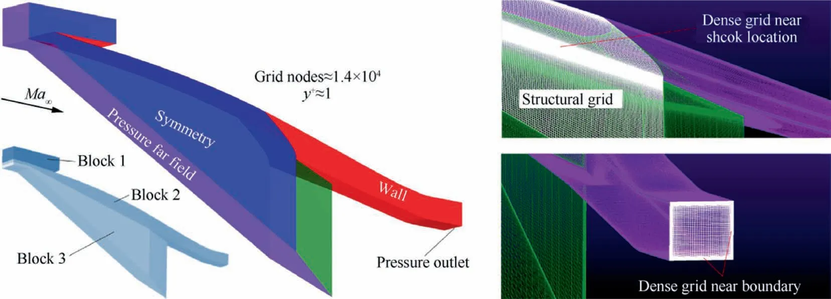
Fig. 11 Computational domains and structural grid.

Table 1 Freestream conditions in wind tunnel.

Fig. 12 Experimental and numerical results in Ma∞=6 flow.
At the design point of Mach number 6, the flow field of streamline traced configuration,observed from the Mach contours shown in Fig. 12(b), inherits the performance of basic flow IBB,in which a leading edge shock is followed by a series of compression waves and a downstream conical shock, and the mass-weighted average of outlet flow Mach number(noted as Ma) is Ma≈2.96. The cowl is covered by leading edge shock, which is very close to spillage window, capturing flow almost completely with a flow coefficient (noted as C)of C≈0.95.Fig.12(b)also shows the outflow total pressure contours by CFD and corresponding pitot pressure distributions by experiments, in which a relatively high total pressure recovery(≈0.85)exists in the region between two lines of yand y, and the mass-weighted average of outlet flow total pressure recovery (noted as σ) is σ≈0.64. In addition, there is a pressure plateau existing in the region between lines of xand xon bottom, as shown in Fig. 12(a). As an incident shock on bottom, the conical shock causes a sudden pressure increase at the position of line x, and the pressure decreases at xposition due to the curved isolator,which induces expansion waves on bottom. However, because the curved isolator also induces compression waves on top,the pressure on top increases sharply at xposition,indicating the uniformity of the outlet flow is affected, which is an unavoidable phenomenon in curved isolator.As a result, the massweighted average of outlet flow static pressure rise (noted as ε) is ε≈23.30.
When the freestream Mach number decreases to 5,the compression waves does not interact on cowl, as shown in Fig. 13(b),and the leading edge shock gets further away from spillage window because of a large shock angle, leading to a less flow coefficient of C≈0.83.The width of relatively high total pressure recovery region between yand yis expanded,resulting in a higher σthat σ≈0.70. The pressure plateau still exists on bottom,as shown in Fig.13(a),in which the position of xmoves upstream due to the change of conical shock strength, and the εand Madecrease to ε≈15.78 and Ma≈2.59,respectively.In the case of Mach number 4,the leading edge shock gets distinctly further away from spillage window, as shown in Fig. 14(b), leading to a much less flow coefficient of C≈0.70, while the σincreases to σ≈0.77. The xposition of pressure plateau moves more upstream, and the εand Madecrease to ε-≈11.53 and Ma≈2.10, respectively. It should be noted that there are large low momentum flow regions in the outflow due to a long isentropic compression, indicating viscosity loss is still distinct, in other words, although the current method integrates successfully forebody, struts and inlet with shock wave interactions as less as possible, the influence of growing thickness of boundary layercannot be avoided.
Figs. 12–14 indicate the self-starting performances of the inlet working in the range of Mach number 6 to 4, and more cases including higher Mach numbers and lower Mach numbers are simulated to investigate the whole starting Mach number range, which are shown in Figs. 15 and 16. Additionally,for further comparison,the key performances of inlet working in various freestream Mach numbers are summarized in Table 2, in which the experimental results (Exp) are obtained based on an estimated method given in the Appendix A.
On one hand, in the low Mach number case, as shown in Fig.15(a),the current inlet model could start in the flow of freestream Mach number 3, although the flow coefficient has dropped to C≈0.56. However, when decrease Mach number continually to 2.7, a large separation bubble appears on bottom near the cowl,as shown in Fig.15(b),inducing a separation shock and thickening the downstream boundary layer on bottom distinctly,leading to a much less flow coefficient of C≈0.35,which is too low to start the inlet flow field.

Fig. 13 Experimental and numerical results in Ma∞=5 flow.

Fig. 14 Experimental and numerical results in Ma∞=4 flow.

Fig. 15 Simulation results for low Mach numbers.

Fig. 16 Simulation results for high Mach numbers.

Table 2 Key performances of current inlet model under various freestream Mach numbers.
On the other hand, in the high Mach number case, as shown in Fig. 16 (a), the inlet still performs well with C≈0.99 and σ≈0.60 in the flow of freestream Mach number 6.5. Similarly, a separation bubble appears on top near the cowl due to Mach number increasing higher to 7, as shown in Fig.16(b).The leading edge shock wave-top boundary layer interaction also thickens the downstream boundary layer on top, which reduces the total pressure recovery distinctly to σ≈0.54.
Therefore, the current inlet model starts from Mach number 3, working till Mach number 6.5, during which the model under Mach number ranging from 4 to 6 shows relatively high performances.
5. Conclusions
The current study proposes a design method for generating aerodynamic configuration of strutjet engine based on a novel combined flow IBB,from which a model of forebody with rectangular inlet and outlet is streamline traced at the design point of Mach number 6,and the performances under various Mach numbers are investigated experimentally and numerically. The following conclusions are obtained.
(1) IBB flow integrates the three-dimensional configurations of forebody, strut, and inlet via combining ICFA, truncated Busemann I, and truncated Busemann II, making full use of forebody and struts to provide additional compressions for inlet,which mainly reduce the aerodynamic loss of shock wave; meanwhile, the profiles of inlet and outlet are streamline traced flexible for various applications;
(2) The current model designed at Mach number 6 performs well in both experiments and simulations under Mach numbers of 6, 5, and 4. The flow field of Mach number 6 is characterized by a leading edge shock covering spillage window, followed by a series of weak waves and a downstream conical shock interacting on cowl, which demonstrate high performances with flow coefficients of C≈0.95,C≈0.95,and total pressure recoveries(mass-weighted average)of σ≈0.62,σ-≈0.64.With the decreasing of freestream Mach number,the leading edge shock gets further away from cowl gradually, resulting in a downward tendency of flow coefficient and an upward tendency of total pressure recovery;
(3) In the low Mach number case,the performance decreases distinctly at Mach number 2.7 by the appearance of separation bubble on bottom,which leads to unstart of inlet;while in the high Mach number case, the performance decreases at Mach number 7 with a separation bubble appearing on top, which induces shock wave-boundary layer interaction,indicating the inlet model starts approximately from Mach number 3 and works till Mach number 6.5 before performance decreases.
Declaration of Competing Interest
The authors declare that they have no known competing financial interests or personal relationships that could have appeared to influence the work reported in this paper.
Acknowledgements
This work was supported by the National Natural Science Foundation of China (Nos. 12072157, 51776096) and China Postdoctoral Science Foundation (Nos. 2019TQ0147,2020M671472).
Appendix A


杂志排行

CHINESE JOURNAL OF AERONAUTICS的其它文章
- Optimal trajectory and downlink power control for multi-type UAV aerial base stations
- Effects of flow parameters on thermal performance of an inner-liner anti-icing system with jets impingement heat transfer
- Effects of wing flexibility on aerodynamic performance of an aircraft model
- Aerodynamic performance enhancement of co-flow jet airfoil with simple high-lift device
- Adaptive fuzzy terminal sliding mode control for the free-floating space manipulator with free-swinging joint failure
- Influence of longitudinal-torsional ultrasonicassisted vibration on micro-hole drilling Ti-6Al-4V