Strategic sill pillar design for reduced hanging wall overbreak in longhole mining
2021-10-26TuoChenHaniMitri
Tuo Chen,Hani S.Mitri
Department of Mining and Materials Engineering,McGill University,Montreal,Quebec H3A 0E8,Canada
Keywords:Underground mine design Longitudinal mining Sill pillar design Unplanned ore dilution Numerical modelling
ABSTRACT Steeply dipping,vein and tabular orebodies are traditionally extracted with longitudinal retreat mining methods such as Eureka and Avoca in a bottom-up sequence with delayed backfill.To increase productivity,sill pillars in the orebody are used to separate mining zones thus allowing production to take place simultaneously in two or more zones.While such mining methods are productive,they may be accompanied with high volumes of hanging wall overbreak causing significant unplanned ore dilution.In this work,it is shown through a mine design case study of a narrow vein deposit that a sill pillar could also play a significant role in limiting hanging wall overbreak.To demonstrate the role of sill pillar,a novel numerical modelling scheme is proposed to account for progressive stope wall overbreak.A numerical modelling approach of element death and rebirth is developed to allow for the detected stope overbreak to be immediately removed and replaced with backfill material before upper-level stope extraction.It is further shown that the average overbreak volume could be reduced by as much as 33%when the sill pillar is strategically placed in the lower half of a mine plan.
1.Introduction
From mine planning point of view,sill pillars are used to divide the orebody into mining zones and this in turn allows production in separate zones to take place simultaneously,thus increasing the overall mine productivity.Another important function of sill pillars is to act as support elements to maintain the stability of the mining system.Sill pillars may be recovered at the end of the life of a mine plan,but this would depend on several considerations such as backfill properties and special ground support provisions in the level immediately above the sill pillar among other factors [1,2].Because of these important functions,the use of sill pillars is vital in mine planning,particularly in longhole mining methods where there is capacity to produce and haul ore from more than one mining zone.
Sill pillar stability has been a topic of great interest to researchers as it is closely related to mine safety.While the thickness of the sill pillar must be adequate to maintain ground stability,it should not be oversized for economic reasons as this would result in lower ore extraction ratio.Pillar dimensioning and stability assessment have been extensively analyzed through empirical,analytical,and numerical methods.Martin and Maybee[3]reviewed existing empirical strength formulas and design charts.Oke and Kalenchuk[4] summarized hard rock pillar design methods,providing guidelines for selecting the most applicable pillar design chart or equation for their specific application.Several analytical solutions have been developed to account for various idealized modes of failure such as plug failure(pure shear failure),elastic beam bending failure,elastic pillar buckling and Voussoir beam failure due to snap thru failure or localized crush failure.Such methods lead to the calculation of safety factor based on the ratio of pillar strength to applied forces [5,6].Kumar et al.[7] conducted a numerical modelling study on sill and crown pillar stability using the finite element method.They determined the pillar thickness based on the extent of yielding within the pillar.Elmo and Stead [8] studied the rock pillar strength using a 2D hybrid numerical model of finite elements and discrete elements.The progressive failure behaviour of jointed rock pillar was simulated to capture the anisotropic and inhomogeneous effects of pre-existing joints.
As can be seen from the above,most of the research in this field focuses on sill pillar stability;little attention has been paid to the influence of sill pillar on ore dilution control.A key aspect of leaving sill pillars in place is to support the overlying stope walls after ore extraction.In this paper,a real-life mine design case study is used to provide a new insight into sill pillar design and its role,not only to separate the orebody into two or more ore zones,but also to control unplanned ore dilution.
The following review will concern itself with recent research efforts on the estimation and understanding of unplanned ore dilution.Overbreak from unstable stope walls is a major concern in longhole mining methods.In addition to contaminating the ore with waste material that is below the cut-off grade resulting in lower mill grade,stope overbreak can significantly increase mining costs due to additional mucking,haulage,crushing,hoisting and milling of waste material.Karian et al.[9]reported that the sill pillar stabilized the stope efficiently by reducing the induced stress from the lower stope,and hence the stope above the sill pillar experienced less yielding failure in the numerical modelling study.El Mouhabbis et al.[10] examined the effect of stope undercut on its wall overbreak using the finite element method.A model parametric study revealed that overbreak increases with the extent of the stope undercut.Urli and Esmaieli [11] modelled hanging wall overbreak of an open stope using discrete fracture network (DFN)method,and a hybrid 3DEC (Distinct Element Code in 3 Dimensions)-DFN modelling is employed to design appropriate ore-skin thickness,which is found to depend on the rock mass quality and stope lifetime.Heidarzadeh et al.[12] assessed the effects of stope geometrical parameters like stope width,stope span,and hanging wall dip on the probability of failure using the finite difference code Fast Lagrangian Analysis of Continua in 3 Dimensions(FLAC3D)to determine optimal ranges of stope geometry parameters.Mitri et al.[13] studied the factors influencing unplanned ore dilution,most notably stope geometry.The effects of stope height and strike length are closely examined with numerical modelling.It is noteworthy that most numerical modelling studies of unplanned ore dilution assessment focus on either the performance of isolated stopes or a mine-and-fill sequence without consideration of the influence of sill pillar.Further,none of the studies reported so far has offered further treatment to the failed hanging wall material in the mine-and-fill sequence[10–15].More specifically,the failed material representing stope overbreak/sloughage is not further treated during the simulation of mine and fill sequence.The purpose of this study is to demonstrate the beneficial influence of sill pillar on stope overbreak volume reduction.To do so,an iterative approach in which the detected stope overbreak is immediately replaced with backfill material before upper-level stope extraction is developed to provide a more realistic estimate of unplanned ore dilution.With this technique,the sill pillar is placed at different mining horizons to determine the optimal pillar horizon that would yield the least overbreak volume.It is shown that the average overbreak volume could be reduced by as much as 33% when a sill pillar is used and strategically placed in the lower half of a mining zone.
2.Case study mine
2.1.Orebody characteristics
This work is part of a feasibility study of a shallow,narrow vein deposit.Data is provided by Kinross Gold Corporation,Canada.Fig.1 shows the geology of the mining area.The mine site is underlain by a bimodal suite of andesite fragmentals,feldsparhornblende porphyry,andesite (trachytic andesite) flows consisting of minor basalt that dips shallowly eastward.Gold-silver mineralization is hosted by colloform to crustiform-banded quartzadularia and polyphase breccias.
A longitudinal section of the vein under study is shown in Fig.2.As can be seen,the orebody is shallow;it is only 35 to 55 m below ground surface.It is open in depth,however,the current mine plan is for the upper portion of 230 m.The strike length of the deposit is approximately 550 m in NW-SE direction,and has a dip of 75° to the SW direction.The vein thickness ranges from 0.1 to 4.4 m,with an average thickness of around 1 m.The red dotted rectangle in Fig.2 outlines the projected mine plan.

Fig.1.Geology of the case study mine.
The orebody is planned to be mined bottom-up using the Avoca method or one of its variants.The method is essentially one of longitudinal retreat longhole mining;see Fig.3.It employs a doubleend access,with extraction from the lower sublevel at one end and backfilling from the upper sublevel at the other end.Sill drives are 4.5 m high and are driven on 15 m intervals.Blastholes are drilled between sublevels to a length of approximately 11 m.A slot is drilled and blasted first to create a void to shoot to if one does not exist and multiple rings are blasted into the void until the planned hydraulic radius is reached.Stopes are filled with waste rock or rockfill from the far end as production advances,typically leaving 20 m of voids to control dilution.The production cycle is repeated until the level is completed.Rockfill is an integral part of the production cycle of the mining method;no cement is used due to economic considerations.
2.2.Geomechanical properties
The mechanical properties of the rockmass and mine backfill were made available from a previous feasibility study of the mine.As can be seen from Table 1,the host rock is relatively weaker than the orebody rockmass with a uniaxial compressive strength (UCS)of 50 MPa compared to 90 MPa for the ore material.The Hoek-Brown(H-B)failure criterion[16]is selected to represent the nonlinear behaviour of the rockmass whereas the rockfill is treated as an elastic material with a nominal modulus of elasticity of 0.2 GPa.
A regional fault is found in the vicinity of the orebody and it runs parallel to the orebody strike.According to Suorineni et al.[17,18] when a fault is very close or intersecting with stope walls,it will have an impact on stope stability.On the other hand,when a fault is located more than 0.3 times the stope height from the orebody,it will have little effect on stope sloughage.In this case study,the closest distance between the fault and the narrow vein orebody is 25 m;the farthest distance is 50 m.As the stope height is 15 m,it is safe to assume the impact of the fault on stope overbreak is minimal.The Mohr-Coulomb criterion is used for the discontinuity representing the fault with the properties shown in Table 2.Due to the absence of fault property data,the fault that developed in hard rock formation is assumed to have no infilling materials.The fault parameters are obtained from a mining-induced faultslip research where ubiquitous joint model is used to represent the fault in hard rock mines [19].
Table 1Geomechanical properties of the rockmass and backfill.

Table 2Regional fault parameters for the numerical model [19].

Table 3HW ELOS values when implementing sill pillars at different levels.
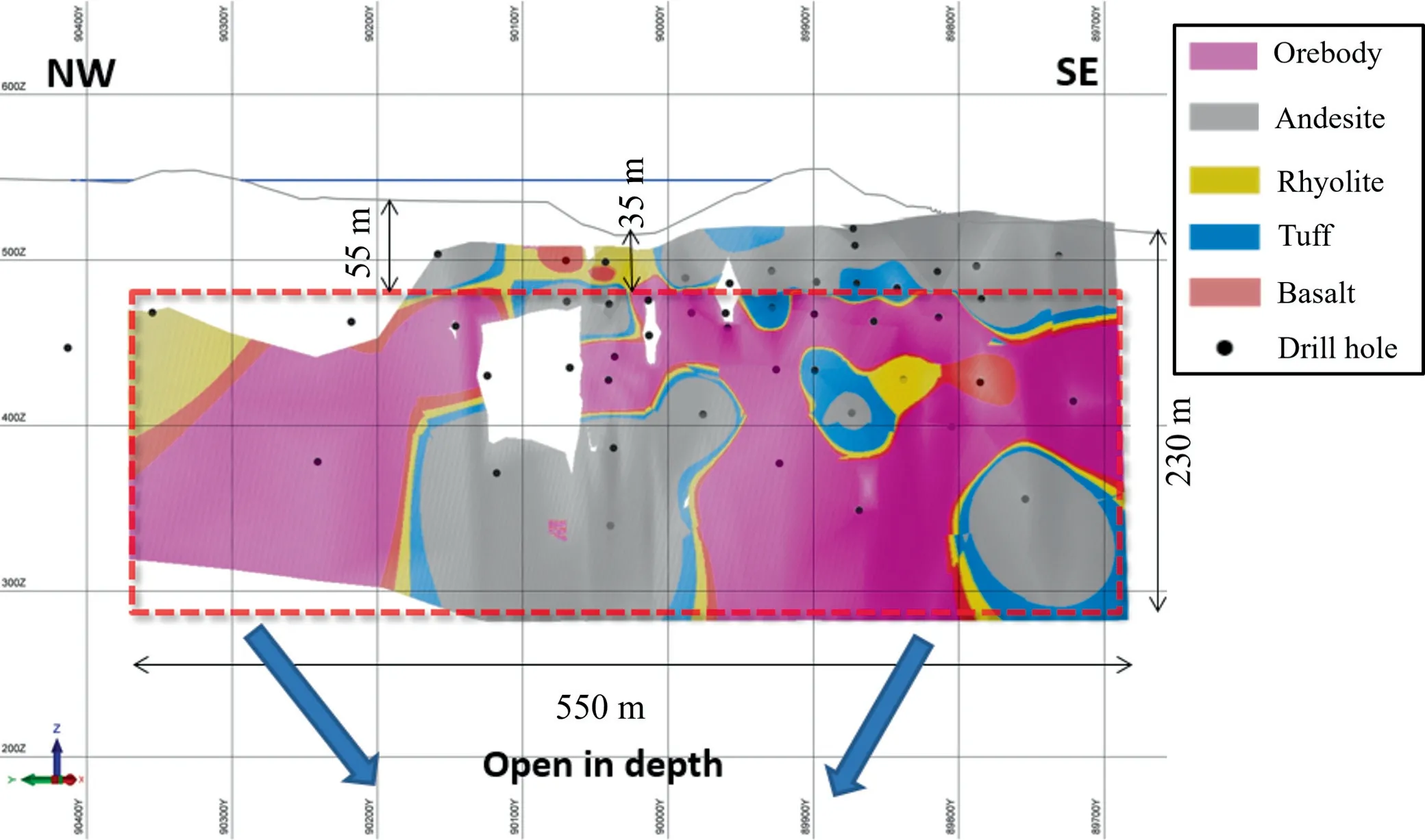
Fig.2.Longitudinal section showing the extent of the studied vein.

Fig.3.Schematic showing longhole mining method.
2.3.In-situ stresses
As no direct measurements are available for this study,the insitu stresses are estimated based on the world stress map data available for this area [20].The vertical stress gradient is 0.027 MPa/m.The horizontal-to-vertical stress ratios are assumed to be 1.5 and 1.8 in x-and y-directions,respectively.Gravity is applied as a body force,and in-situ stresses are initialized by applying horizontal-to-vertical stress ratios in the domain.The relations between horizontal stresses and vertical stress in numerical modelling are defined as follows:

whereHis the depth below ground surface;ρ the rock density;gthe gravitational constant;andthe in-situ stresses in x-,y-,and z-directions,respectively.
3.Numerical model
3.1.Numerical modelling scheme
The traditional numerical modelling technique that has been reported so far in literature applies the backfill material to the planned stope volume and not to the stope volume after it has experienced overbreak.This could lead to underestimation of the overbreak on subsequent stopes.Henning and Mitri [21] analyzed hanging wall(HW)dilution data measured by the Cavity Monitoring System(CMS)at the Bousquet#2 mine.They reported that HW overbreak associated with the primary stopes analyzed is less than that of the secondary stopes in Zone 3–1.This observation supports the hypothesis that a stope overbreak,inherently influences the overbreak of the next–immediately adjacent or above–stope,as secondary stopes are mined after the primary stopes have been extracted.
In the following,a novel modelling scheme is described for the simulation of unplanned dilution and hence illustrate the role the sill pillar plays in dilution control.In practice,overbreak is in effect a cavity that extends beyond the planned stope boundary.The failed material would naturally cave by gravity and is mucked out with the blasted ore.Thus,the stress relaxation zone around the planned stope boundary should further retreat to encircle the cavity created by overbreak.The removal of failed (yielded) material volume and replacing it with backfill has two distinct effects onsubsequent stope extraction.First,element removal causes the state of stress in the failed material to vanish and be replaced by state of a zero-stress of the rockfill material.Secondly,the stiffness of the failed material,even though in the post-peak range,is still an order of magnitude greater than that of the rockfill.These two factors lead to inherently weaker HW,which influences the stability of the overlying stope to be extracted.This modelling approach of element death and re-birth has been implemented in a FISH code and embedded in FLAC3D.
In this study,the HW overbreak is evaluated to represent the unplanned dilution potential since the HW has much more dominant overbreak volume than that from the footwall when mining steeply dipping narrow-vein deposits [22].
3.2.Model setup
The finite difference code FLAC3D developed by Itasca Ltd is used in this study.FLAC3D uses explicit formulation that can analyze non-linear material behavior and capture failure/yielding zone development in a model consisting of several operation stages.As shown in Fig.4a,the model extends 570 m in the y-direction to situate the boundaries far enough from the orebody cross section and the HW fault.In the depth or z-direction,the model extends 520 from the ground surface to well below the lowest level of the orebody.Considering that the mining method is longitudinal retreat,it is reasonable to assume that the stope behaviour is similar along the orebody strike.Thus,a 10 m long strip of the orebody in the x-direction is deemed sufficient to analyze.This necessitates a plain strain condition to be applied to the x-faces of the model;see Fig.4b.Thus,displacements are constrained to occur only in YZ plane.The vein has a vertical extent of 245 m and a uniform width of 4 m,as the possible drift dimensions are 4 m× 4 m.The minimum mesh size is 0.5 m around stopes.
Regarding kinematic boundary conditions,rollers are applied to the bottom and vertical sides of the model as shown in Fig.4.The model outer boundaries are far enough and constrained to a minimum to avoid undesired development of local stress concentrations near the boundaries.The ground surface is free.
3.3.Initial model results
The vein is simulated to be mined bottom-up and backfilled at 15 m intervals.The yielded areas on the stope HW are treated as overbreak prone to caving and are thus eliminated after stope excavation as previously described.The initial FLAC3D model has no sill pillar,i.e.,the entire orebody is extracted.This would be a reference model to demonstrate the importance of sill pillar in ore dilution control,which is the purpose of this study.In the first instance,the new method is compared with the traditional modelling technique which replaces only the planned stope volume with backfill.The results are shown in Fig.5,whereby overbreak is shown by the red areas.It can be observed the HW overbreak using the new method is clearly larger than that predicted by the conventional modelling method.This is particularly evident in the middle third of the orebody.
Fig.6 shows the local minimum principal stress contours when mining level 7.The positive stress values shown in the legend represent tension whereas the negative values represent compression.The mining-induced relaxation (tension) area,caused by previous stoping activities,is shown in red;it is herein referred to as“stress shadow” zone,which is delineated by the whited dotted polygon.Comparing the stress shadow zones in Fig.6a and b from the conventional and new methods,respectively,shows that the latter is significantly larger.The larger stress relaxation zone leads to larger HW overbreak.
To quantify the model results,the predicted overbreak results will be calculated in terms of the equivalent linear overbreak slough (ELOS) proposed by Clark &Pakalnis [23].An illustration of the calculation method is shown in Fig.7.The ELOS is calculated by the equation below.


Fig.4.FLAC3D model of the case study deposit.

Fig.5.FLAC3D initial model results without sill pillar.
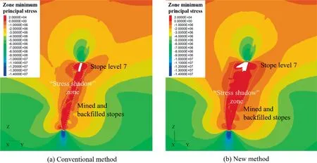
Fig.6.Stress shadow zones caused by preceding stoping activities (unit:Pascal).

Fig.7.Equivalent linear overbreak/sloughage (ELOS) [23].
For the purpose of reporting the overbreak modelling results,the volume of slough in Eq.(4) will be equated to that predicted by the model,and the stope surface area is 150 m2.The results of the overbreak calculations are plotted in Fig.8 in terms of ELOS.As can be seen,the HW ELOS predictions are significantly different by the new and conventional modelling techniques,being much higher for the new method(blue plot in Fig.8).In terms of average HW ELOS,the new method predicts an average ELOS of 5.8 m compared to 3.5 m using the conventional method.

Fig.8.Comparison of the predicted HW ELOS between conventional and new methods.
4.Sill pilar design
The following analysis will focus on the influence of sill pillar placement on the control of HW overbreak.To do so,several FLAC3D models have been created to model various positions of the sill pillar within the orebody.As previously mentioned,while the topic of sill pillar design has been extensively studied,no study has been reported yet on the role and importance of sill pillar in stope overbreak control.

Fig.9.HW overbreak model results with different sill pillar locations.
From a mine planning perspective,sill pillar is traditionally placed at mid-height of the orebody to create approximately two equal size mining zones for higher productivity [24–26].In this study,a sill pillar will be positioned on levels 5,6,7 and 8 to examine the impact of sill pillar placement on the overbreak volume.The results will help identify the optimal sill pillar placement.Given the low in-situ stress environment of the orebody (mining depth <500 m),the sill pillar stability assessment will not be examined in this work.The pillar thickness is assumed to equal to that of a level interval,i.e.,15 m.This is a reasonable assumption from mine planning point of view.
The HW overbreak results for different numerical models representing different pillar placements are presented in Fig.9.Two observations can be made in light of these results.First,overbreak gradually increases with the mining direction,which is a reflection of stress shadow build up due to previously mined(lower)stopes.Secondly,the stope overbreak immediately above the sill pillar is considerably smaller than that of the stope immediately below.This is a demonstration of the benefit of sill pillar placement in the reduction of unplanned dilution.

Fig.10.HW ELOS versus mining levels in pillar placement schemes.
Fig.10 plots HW ELOS for different sill pillar locations.Compared with HW ELOS results without sill pillar (initial model),all four sill pillar models show considerably less ELOS from mining levels above the sill pillar,e.g.,HW ELOS decreases from 6.6 m at level 4 to 1.96 m on level 6 when the sill pillar is placed on level 5.These observations suggest that the sill pillar has a significant effect on HW ELOS.

Fig.11.Sill pillar separating stoping levels to reduce stress shadow build up due to lower zone mining (unit:Pascal).Note:Positive principal stress values represent tension.
To better understand the role of the sill pillar in reducing potential unplanned dilution,the minimum principal stresses for mining level 6 are plotted as shown in Fig.11.It is shown that the sill pillar significantly reduces overbreak in the stope immediately above the sill pillar.As the mining method is inherently a bottom-up extraction,the stress shadow created by previous lower-level mining increases as mining proceeds upwards,thus causing further overbreak.Therefore,the stope immediately above the sill pillar,being the first in the sequence of bottom-up mining,is expected to produce much less overbreak than the one immediately below the pillar which is the last of the bottom-up sequence.
Table 3 presents the HW ELOS values when placing the horizontal sill pillar on different levels.It can be observed that the average HW ELOS decreases significantly in all cases with the sill pillar placement.What stands out in Table 3 is that leaving a sill pillar at a lower level than the mid-height of the orebody such as level 5 or level 6 is optimal as the average ELOS drops to 3.9 m.Another equally important observation is that such optimal sill pillar placement,when compared to the initial model with no sill pillar and ELOS of 5.8 m,represents an overbreak volume reduction of 33%.
5.Conclusions and recommendations
While sill pillars are traditionally designed to create multiple mining zones to increase productivity and maintain the stability of the mining system,this paper examines sill pillar design from a new perspective and that is the role it can play on the control of HW overbreak volume.A novel numerical modelling scheme is implemented in finite difference code FLAC3D whereby HW potential overbreak areas are removed and immediately replaced with backfill material using an element death and rebirth technique in the mine-and-fill simulation sequence.The technique is coded with FISH language embedded in FLAC3D.A real-life mine design case study of a shallow,steeply dipping,narrow vein deposit has been used to demonstrate the merits of sill pillar design for ore dilution control.The following conclusions can be drawn from this work.
The proposed overbreak modelling scheme of element death and rebirth is novel;it removes then backfills yielded zones in the stope HW representing overbreak material.This is a more realistic sequence to delineating stope final geometry than conventional mine-and-fill sequence which keeps the planned stope geometry unchanged.
Overbreak occurring in stope HW is a gravity-driven failure mechanism that develops during stope extraction.The proposed modelling method assumes a worst-case scenario that all potentially unstable HW overbreak volume falls by caving,resulting in a larger cavity than planned stopes.
A comparison between conventional and new modelling technique reveals that conventional numerical modelling may not be conservative in estimating unplanned dilution.
Sill pillar design analyses show reduced overbreak regardless of the position of the sill pillar within the orebody.This goes to highlight an important function of sill pillar design in addition to its role as a ground support element and divider of mining zones.
The common practice is to place the sill pillar at mid-height of the orebody.This may not be the best position for dilution control.Based on the parameters of the case study mine,the optimal location of the sill pillar is on level 5 or 6 in a 15-level mine.However,this could vary under different mining and geological conditions.
In this case study,by strategically positioning the sill pillar,the HW overbreak could be reduced by as much as 33%.
While the new modelling technique is believed to be more realistic than conventional modelling,it should be first calibrated with field measurements of overbreak before it can be deployed as a tool for the prediction of unplanned ore dilution.The focus of this study has been to advocate the role of sill pillar design to control overbreak volume.The mine case study has helped to provide reallife data to demonstrate the sill pillar design concept.Thus,the calibration of the new method is required if it were to be used for dilution assessment.The sill pillar design optimization exercise may not require validation as it is a direct application of stress analysis.This work analyzed the stope overbreak of a longhole mining case when one sill pillar is placed.However,the proposed modelling scheme can be equally applied to cases with multiple sill pillars (in larger orebodies).
Acknowledgements
This work is financially supported by the Natural Science and Engineering Research Council (NSERC)–Discovery Grants Program.The authors gratefully acknowledge Kinross Gold Corporation for providing the data of the mine case study.Special thanks are due to Dr.Jerry Ran from Kinross for his time and technical discussions.
杂志排行

矿业科学技术学报的其它文章
- Effects of confining pressure on acoustic emission and failure characteristics of sandstone
- Understanding the influence of petrographic parameters on strength of differently sized shale specimens using XRD and SEM
- Experimental investigation of rigid confinement effects of radial strain on dynamic mechanical properties and failure modes of concrete
- Dynamic Mode Ⅱfracture behavior of rocks under hydrostatic pressure using the short core in compression (SCC) method
- Investigation of the influence of intermediate principal stress on the dynamic responses of rocks subjected to true triaxial stress state
- Experimental study on the infrared precursor characteristics of gas-bearing coal failure under loading