Analysis on diffusion-induced stress for multi-layer spherical core–shell electrodes in Li-ion batteries∗
2021-09-28SiyuanYang杨思源ChuanweiLi李传崴ZhifengQi齐志凤LipanXin辛立攀LinanLi李林安ShibinWang王世斌andZhiyongWang王志勇
Siyuan Yang(杨思源),Chuanwei Li(李传崴),†,Zhifeng Qi(齐志凤),Lipan Xin(辛立攀),Linan Li(李林安),Shibin Wang(王世斌),and Zhiyong Wang(王志勇),‡
1Department of Mechanics,School of Mechanical Engineering,Tianjin University,Tianjin 300350,China
2Tianjin Key Laboratory of Modern Engineering Mechanics,School of Mechanical Engineering,Tianjin University,Tianjin 300350,China
Keywords:multi-layer spherical core–shell electrode,diffusion-induced stress
1.Introduction
Rechargeable lithium-ion batteries(LIBs)have the advantages of large storage capacity,high energy density,good stability,and excellent cycle capability,which become dominant power sources in many fields including portable electronic devices and electric vehicles.[1–5]In recent years,a host of improved strategies of LIBs techniques are proposed to satisfy the increasing demand for better LIBs’performance,such as high efficient manufacturing processes,advanced materials,innovative and heteromorphic battery.[6–9]The anode,as an integral part of the LIBs,plays an important role in determining the key performance including the energy density and the cycle ability.[10]As one of the most promising anodes,silicon(Si)has drawn great attention due to its high theoretical capacity of 4200 mAh·g−1.[11]Nevertheless,commercial applications of Si anodes are hampered owing to their considerable volumetric changes(greater than 300%)which directly lead to electrode failures during the lithiation/delithiation process.
Currently,based on mechanical fundamental,[12]studies on the deformation of Si electrodes have put forward various diffusion-induced theories,[13–17]meanwhile,damage,[18–20]and fracture[21]based on diffusion-induced theory also draw attention.The new solid electrolyte interphase(SEI)layer forms over the surface,resulting in rapid capacity attenuation and poor rate performance.[4,22,23]Besides,inherent low conductivity leads to poor rate capacity and low utilization rate of electrode materials.[24]The structural damage to electrode materials during charging and discharging processes causes performance degradations.[25,26]In a word,mechanical damages have a critical influence on the performance and service period of the LIBs.[27]In recent years,tremendous progresses have been made on the above mentioned problems by using siliconcarbon composite(Si/C)with graphite.The Si/C composite has been proved to be beneficial to decrease the volumetric variation of silicon anodes.[4]
Especially,structures of Si/C spherical electrodes have been broadly investigated,such as spherical core–shell nanoparticles and coated-hollow electrode particles.[28]Spherical core–shell(SCS)electrode is believed as an excellent structure to realize stable electro-mechanical behaviors.[29]Mechanical investigation on SCS is indispensable in evaluations for SCS-based LIBs performance and service life.Based on elastic–plastic theory,evolution law of stress and strain has been analyzed.[30–34]
As mentioned above,the most previous studies have focused on deformation and damage of monolayer or bilayer spherical electrode particles.In this paper,an electrochemical-/mechanical-coupling model of the multilayer spherical core–shell(M-SCS)electrode with graphite framework is developed to maintain the stability of the electrode structure and to obtain higher capacity density.It is generally known that the electrochemical/mechanical degradation limits the increasingly wide range of applications of cells with silicon electrode.Accordingly,it is critical to analyze the mechanical performance of electrode materials for promoting electrochemical performance of LIBs.Similarly,in order to understand electrochemical-/mechanical-coupling mechanism of the multilayer spherical core–shell(M-SCS)electrode,it is necessary to establish diffusion-induced stress models applying to the M-SCS electrode.
As depicted above,significant volume change of Si electrode hinders its development,giving rise to more mechanical problems compared with other electrodes Therefore,Chen et al.[4]prepared carbon-coated silicon-based spherical composite with consideration of superiority of hierarchical structure to improve electrochemical performance.However,it is not clear how the stress affects carbon-coated silicon-based spherical composite.An Si@O-MCMB/C nanoparticle is hence taken as an example,in which an electrochemical model with consideration of particles mutually coupling has been presented and developed.The rest of this article is divided into the following sections.In Section 2,the diffusion-induced stress model in the M-SCS electrode particles is developed.In Section 3,the impact of some parameters on the electrode stress is discussed and analyzed.Finally,we summarize the work in Section 4.
2.M-SCS model
2.1.Geometric model
An isotropic diffusion system with three-phase(phases ofα,β,andγ)multilayer-core–shell structure is considered,taking the Si@O-MCMB/C nanoparticle as an example(see Fig.1(a)).To carry out mechanical analysis on the M-SCS structure,the spherical symmetry is taken into account and the structure is simplified,as shown in Fig.1(b).Theαcore is graphite as a framework of the M-SCS structure due to its excellent electrical conductivity.A combination of Si and graphite is a fine approach to surmount weakness of low electrical conductivity of Si.[4,35,36]Theγ-outer-shell(carbon)separates the electrolyte and the electrode(β-medium-layer Si andα-core graphite).Carbon shell as a protective layer does not undergo lithiation reaction and contributes to restrain the fracture of Si.[4,35,36]The three-phase structure allows the expansion of silicon to receive both internal and external constraints,due to the minute deformation of lithiated graphitecore and non-reaction of carbon-shell with lithium.[4,37]The structure has a considerable advantage in designing and improving electrodes.The three-phase structure enhances the capacity,mechanical and chemical stability of Si/C anodes simultaneously.The continual solid electrolyte interphase(SEI)cracking and reforming are restrained,owing to the outward expansion of the intermediate layer limited by the outer shell,which ensures to maintain the electric contact between the electrode and the matrix.A similar structure design shows the prospect of a high-capacity electrode with hundreds of cycles.[4]The diffusion-induced stress/strain equation appropriate for the core–shell model has been investigated by several researchers.However,there are still less reports on the study of modeling for the stress/strain evolution process within a multilayer-core–shell framework.Worth mentioning is that there exists a large discontinuity in composition,stress,and strain across a propagating phase boundary in lithiated electrode materials.Therefore,it is critical to take into account the effect of the multi-dimensional inhomogeneity of electrodes for battery analysis and estimation.
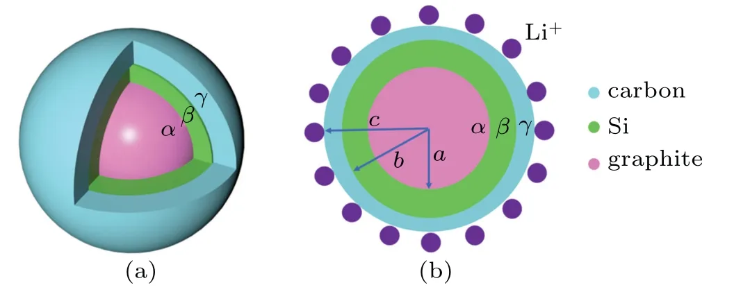
Fig.1.(a)Schematic diagram of the M-SCS phase,(b)geometric structure of the M-SCS.
2.2.Stress model of the M-SCS
2.3.Single multilayer-core–shell particle


The diffusion-induced stress is an analogy to thermal stress according to Prussin’s research.[38]The constitutive relationship equations of the stress and strain can be expressed as[39]

where E is the Young’s modulus and v is the Poisson’s ratio.Since we consider the response as quasi-static in this study,E and v are assumed to be constant.C(r,t)is the molar concentration of lithium with insertion into material elements,andΩ is the partial molar volume of solute.The displacement field is radially symmetric due to the spherically symmetric structure of the material.Meantime,the radial and tangential strain of the multilayer-core–shell spherical nanoparticle can be expressed with functions of radial displacement ur,as
For the local coordinate system is used for a single particle,there is no displacement at the center of the nanoparticle,and thus ur(0)=0.The displacement u(r)is expressed as[39]

where P and Q are parameters,which can be determined by the boundary conditions forα,β,andγphases.r0is the inner radius of the three-phase.In accordance with the boundary conditions for the multilayer-core–shell spherical nanoparticles,the following equation is determined,

Therefore,the radial and tangential stress are given as
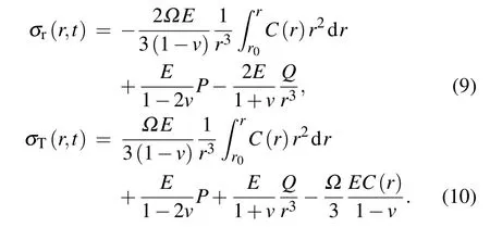
Specifically,the hydrostatic stress is expressed as follows:


According to Fang et al.’s work,[40]the surface/interface stress has a significant impact on diffusion-induced stress of the spherical core–shell electrodes.In this research,we take into account its effect on diffusion-induced stress of the MSCS electrodes.Furthermore,the influence of coreshell surface/interface stress modulus ratio on silicon sandwich layer was studied.For an elastically isotropic model,the surface/interface stress Sθcan be expressed as

whereτis the deformation-indepent residual surface/interface stress.K is defined as the surface/interface modulus,andεθis the surface strain corresponding to Sθ.The molar concentration equations can be further written as
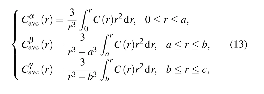
where a,b,and c are the outer radii of each material phase in multilayer-core–shell,as shown in Fig.1(b).
We extend the diffusion-induced stress solution from a single phase to three-phase in spheroidal particle.For the three-phase multilayer-core–shell structure,there are six constants of the three materials denoted by P1and Q1of materialα,P2and Q2of material-β,P3and Q3of material-γ.For the α-core with 0≤r≤a,there are

At the center of spheroidal core–shell electrode particle(r=0),Q1=0 as a result of ur=0.For theβ-medium-layer(Si)with a≤r≤b,there are

For theγ-outer-shell with b≤r≤c,there are

At the outer surface,there is

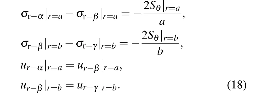
At the junction interface of two materials,there are
2.4.Diffusion equation in spherical multilayer-core–shell electrodes
In the multilayer spherical core–shell(M-SCS)the lithium-ion transport is a concentration driven diffusion process.[41]The species flux is expressed as[42]

where M is the mobility of the lithium-ion.The driving force for the movement of lithium-ion is the gradient of chemical potentialµ,[43]considering the effect of the hydrostatic stress on diffusion

in whichµ0is the constant,R and T are the gas constant and the absolute temperature,respectively.X is the molar fraction of the lithium-ion.Besides,the diffusion coefficient is written as D=MRT.Substituting Eq.(20)into Eq.(19),we get another expression of parameter J with assumption of temperature uniformity as follows:

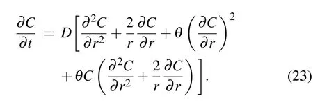
where D=MRT is the diffusion coefficient.θis a normal constant describing the extent of the influence of hydrostatic stress on the diffusion flux,[40]θ=2Ω2E/[9(1−v)RT],obtained from Eq.(11).The conservation of species is given by

Finally,substituting Eq.(21)into Eq.(22),we can obtain that
The initial and boundary conditions are

At the interface of theα/β,it can be obtained that

At the interface of theβ/γ,it can be obtained that

2.5.Numerical solutions
The governing equations obtained above are numerically solved.Owing to the central symmetry,the structure of spherical particles can be simplified as a one-dimensional model from Eq.(14)to Eq.(23).Finite difference method(FDM)is applied herein to solve nonlinear Eq.(23)based on the boundary conditions Eqs.(24)–(26).Subsequently,the stress values are determined through by means of fitting the discrete concentration to a continuous concentration function.Material properties of the employed three materials are listed in Table 1.The constant of lithium ion concentration is set to be 1.2×10⁴as on the outer surface of the spherical electrode active material particles during the lithiation process.

Table 1.Parameters of the materials.
3.Results and discussion
To reveal the effect of the diffusion-induced stress with carbon shell,two situations are compared firstly:one containing carbon shell,the other in the absence of the carbon shell.During the lithiation process,in contrast with the other two phases,the silicon material phase experiences maximum tensile stress due to the large volume expansion.Figure 2 shows the diffusion-induced stress of the two cases when the maximum tensile stress occurs in the silicon layer.Both shell thickness ratio of the carbon phase(Δ2/c)and shell thickness ratio of the silicon phase(Δ1/c)are 1/3,and Young’s modulus of the carbon shell is 1 GPa.Because of the discrepancy of the three material properties and the influence of the surface/interface stress,the discontinuity and jump of the stress distribution are observed clearly in the two cases.Besides,there are mild stress changes in the graphite material phase and dramatic stress changes in the silicon material phase,related to the concentration gradient.From Fig.2,the presence of the carbon shell greatly decreases the maximum tensile stress of the silicon material phase.Silicon-based spherical core–shell electrode particles employ carbon shell where lithium reaction is not produced,hence the stress of the carbon shell mainly results from the silicon expansion.The carbon shell in turn limits the increase of stress in the tangential and radial direction.
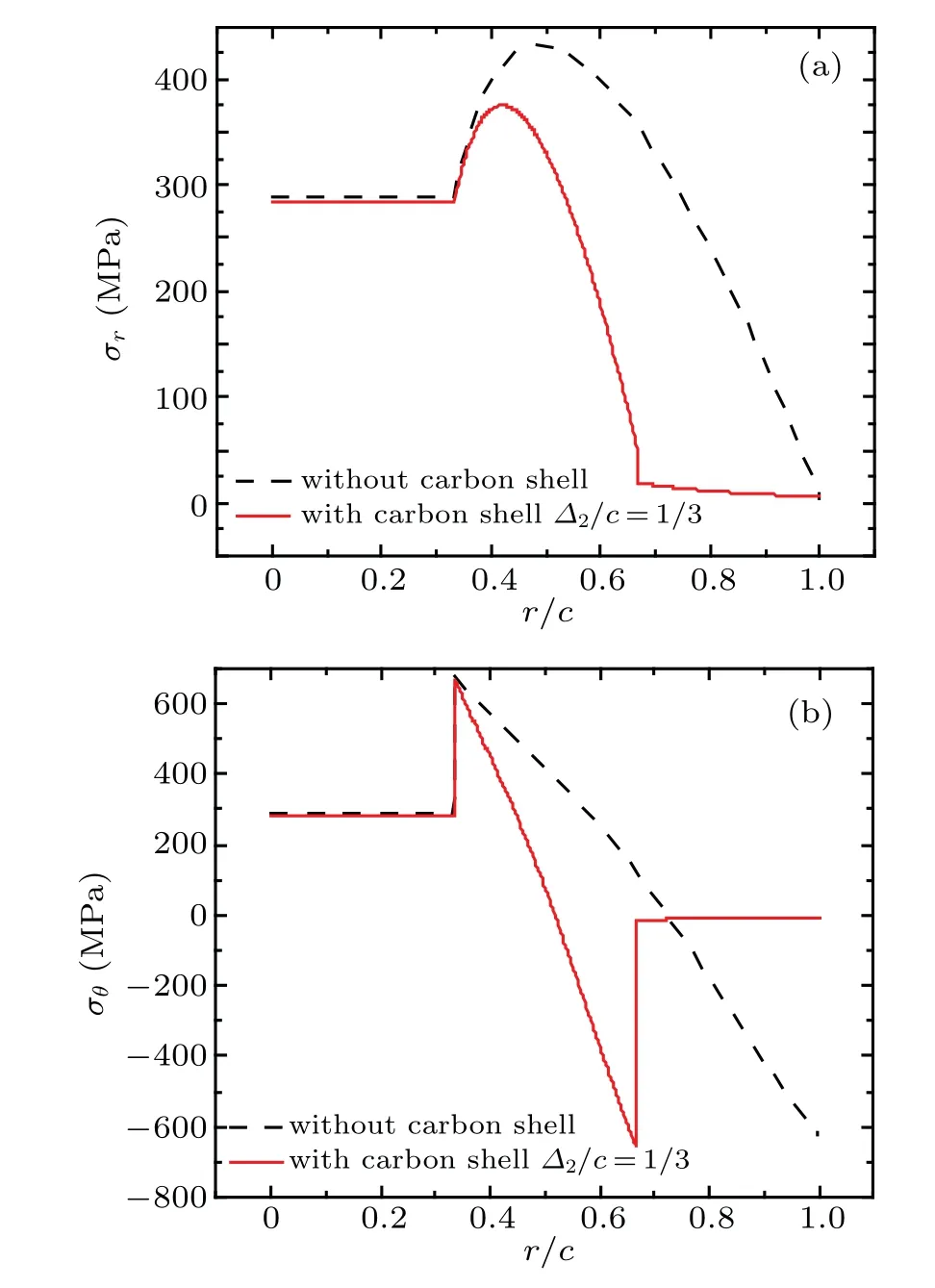
Fig.2.Diffusion-induced stress of two cases when the maximum tensile stress occurs in the silicon layer:(a)radial stress and(b)tangential stress.
3.1.Effect of elastic modulus ratio on sandwich silicon materials
Since Young’s modulus of the carbon shell ranges from 1 GPa to 20 GPa,it is necessary to study the impact of the variation of Young’s modulus of the carbon shell on the stress field of multilayer core–shell structure.E3/E1equaling to 0.1,0.5,1,and 1.5 respectively is investigated.The shell thickness ratio of the carbon material phase and silicon material phase is still 1/3.As shown in Fig.3,the diffusion-induced stress with four different Young’s modulus versus r/c is obtained when tensile stress in the silicon material phase reaches the maximum.In the radial direction,the tensile stress of the three-phase reduces with the decrease of E3/E1.Similarly,in the tangential direction,both the tensile stress in the graphite/silicon and the compressive stress in the carbon also reduce when E3/E1decreases.To sum up,the decrease of E3/E1not only makes the diffusion-induced stress of carbon tend to be zero,but also alleviates the tensile stress of inner materials.

Fig.3.The diffusion-induced stress of four different Young’s modulus,(a)radial stress and(b)tangential stress.
3.2.Effect of surface/interface modulus K ratio on sandwich silicon material
Next,the effect of surface/interface stress is considered.The residual surface/interface stressesτin the three surface/interface are all supposed to 0 N/m.To investigate respectively effect of surface/interface modulus K1,K2,K3on multilayer core–shell structure,one of surface/interface modulus is assumed to 0 N/m and±10 N/m respectively and the other two surface/interface modulus keep constant.Otherwise,the dimensionless time D2t/c2equals 0.1,shell thickness ration of the carbon material phase and shell thickness ratio of the silicon material phase are 1/3,and E3=1 GPa.Figures 4(a)and 4(b)indicate that positive interface modulus K1tends to decrease diffusion-induced stress in the graphite material phase,on the contrary,negative interface modulus K1increases diffusion-induced stress.However,positive interface modulus K2leads to increasing diffusion-induced stress in the graphite material phase and in the silicon material phase,and negative interface modulus K2reduces diffusion-induced stress,as shown in Figs.4(c)and 4(d).Similarly,in Figs.4(e)and 4(f),positive surface modulus K3increases diffusioninduced stress in the entire structure,and negative surface modulus K3reduces diffusion-induced stress.To sum up,as the surface/interface modulus change,the diffusion-induced stress of material phase which is wrapped by surfuce/interface is influenced.Moreover,the effect of K2on the silicon materials phase is the furthest.
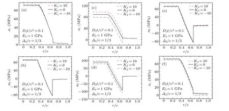
Fig.4.The effect of surface/interface modulus K on stress distribution:(a)and(b)K1,(c)and(d)K2,(e)and(f)K3.
3.3.Effect of shell/core thickness o on sandwich silicon materials
Finally,the effect of the carbon–shell thickness is also studied.The carbon–shell thicknessΔis subsequently chosen as 0.5 nm,2.5 nm,5 nm,and 7.5 nm.the other parameters E3=1 GPa and D2t/c2=0.1.Figures 5(a)and 5(b)show the distribution of radial and tangential stress.they indicate that the stress can be reduced effectively by the increase of the carbon–shell thickness.However,the increase of the carbon–shell thickness leads to decreasing the specific capacity of electrode particles.As a result,carbon–shell thickness is as thin as possible within the endure of material strengths.

Fig.5.The effect carbon thickness on diffusion-induced stress:(a)radial stress and(b)tangential stress.
4.Conclusion
In this work,an electrochemically-/mechanically coupled model for a novelly proposed M-SCS structure made from Si@O-MCMB/C nanoparticles has been established,in which the diffusion-induced stresses along various directions in each material phase can be expressed and determined based on the finite difference method(FDM).Through a calculation for the stress,it can be concluded that,compared with those traditional dual-layer core–shell(CS)structures,the M-SCS with an external carbon-shell can remarkably reduce the tensile stress of theβ-medium-layer,namely the silicon layer.Moreover,influences of parameters including the Young’s modulus,the surface/interface modulus,and the thickness of each layer on the stress have been also presented.Results show that,(i)with the Young’s modulus of the carbon–shell decreasing,the expansion of the silicon phase is effectively limited and the tensile stress in the silicon reduces,(ii)the parameter of K2affects the stress of the silicon phase furthest among all the surface/interface modulus,(iii)on the premise of the strength requirements,the smaller the thickness of the carbon shell can be,the higher the specific capacity of the overall structure can achieve.
猜你喜欢
杂志排行
Chinese Physics B的其它文章
- Origin of anomalous enhancement of the absorption coefficient in a PN junction∗
- Protection of isolated and active regions in AlGaN/GaN HEMTs using selective laser annealing∗
- First-principles study of plasmons in doped graphene nanostructures∗
- Probing thermal properties of vanadium dioxide thin films by time-domain thermoreflectance without metal film∗
- An improved model of damage depth of shock-melted metal in microspall under triangular wave loading∗
- Signal-to-noise ratio of Raman signal measured by multichannel detectors∗
