Interface effect of C3N4-Ti4O7-MoS2 composite toward enhanced electrocatalytic hydrogen evolution reaction
2021-08-15DUJiafengZHAOJianghongRENJun
DU Jia-feng,ZHAO Jiang-hong,REN Jun,*
(1.State Key Laboratory of Clean and Efficient Coal Utilization,Taiyuan University of Technology,Taiyuan 030024,China;2.Key Laboratory of Coal Science and Technology,Ministry of Education,Taiyuan University of Technology,Taiyuan 030024,China;3.Engineering Research Center for Fine Chemicals,College of Chemistry and Engineering,Shanxi University,Taiyuan 030006,China)
Abstract:Electrocatalytic water splitting is one of the most prospective technology for hydrogen production.Molybdenum disulfide (MoS2),as one of the most promising non-noble metal electrocatalysts,suffers from the disadvantages of limited catalytic sites and weak conductivity which urgently needs to be further optimized.Herein,the C3N4-Ti4O7-MoS2 heterostructure is constructed through a simple hydrothermal strategy.The interfacial interaction between the active components leads to more exposed active sites,the redistribution of the surface charge,the optimization of the hydrogen adsorption kinetics and stability,which makes up the typical shortcomings of MoS2.The results indicate that the interface effect endows C3N4-Ti4O7-MoS2 catalyst with excellent electrocatalytic activity for hydrogen evolution reaction (HER).The current density of 50 mA/cm2 for HER is obtained at the overpotential of 300 mV,with the lower Tafel slope (54 mV/dec) and stable catalytic activity over 33 h,which is much better than that of the pure MoS2.This work indicates that the interface effect,as an effective strategy for rational design of MoS2-based electrocatalysts,is crucial to the future development of catalytic hydrogen production.
Key words:electrocatalytic water splitting;molybdenum disulfide (MoS2);carbon nitride (C3N4);Ti4O7;interface effect;hydrogen evolution reaction (HER)
It is urgent to develop the green hydrogen production technology to cope with the energy crises and environmental deterioration.Among the hydrogen production technologies,hydrogen evolution reaction(HER) from water electrolysis is cleaner and more efficient.Much attention have been paid to the development of more excellent and stable electrocatalysts for the reaction.At present,platinum(Pt) group metals are the most superior electrocatalysts for HER.However,the high cost and the scarcity of the earth reserves seriously limit its large-scale application[1].Thus,great efforts have been made to develop nonprecious electrocatalysts with excellent HER performances.
Molybdenum disulfide (MoS2) is one of the most promising non-precious candidates whose edge sites have the free energy for hydrogen adsorption similar to that of Pt[2].However,its basal plane is catalytically HER-inert.In addition,the graphene-like structure of MoS2mainly has two crystal phases,i.e.common 2H phase and unstable 1T phase obtained by the displacement of S layer.The 2H-MoS2is a semiconductor while the 1T-MoS2is a metal.Based on the free energy of hydrogen adsorption,1T-MoS2has better hydrogen production performance in comparison with 2H-MoS2.However,the stability of 1T-MoS2is extremely poor due to its high formation energy[3−5].Therefore,a lot of researches are devoted to improve the HER activity of MoS2.The strategies include,for e xample,nanostructuring[6−10],phase tuning[11−13],defect engineering[14−17]and heteroatom doping[5,18−20]etc.Although great progresses have been made,there is still a big gap between the MoS2-based and the Ptbased electrocatalysts.
In recent years,carbon nitride (C3N4) with a graphene-like frame structure has attracted much attentions as photocatalysis and electrocatalysis due to its semiconductor characteristics and the lamellar structure[21−23].Thus,intercalation of C3N4into MoS2to build a graphene-like heterojunction is expected because the strong interaction between C3N4and MoS2may lead to the formation of coordination structures conducive to charge transfer and the creation of new catalytic sites.For example,Zhao et al.found that Mo-N coordination formed between MoS2and C3N4through in-situ synthesis promotes the electron transfer at the MoS2/C3N4interface which act as the main active site for electrocatalytic nitrogen reduction reaction[21].The photocatalyst prepared by Li et al[22],with g-C3N4grown on MoS2,can effectively separate and transfer carriers and greatly improve the photocatalytic water splitting under visible light irradiation.
Titanium suboxide (Ti4O7) is an environmentally friendly,non-toxic inorganic composite material,containing a large amount of unsaturated titanium,which can generate coordination structures with other active components beneficial to the transfer of electrons and the conductivity of the catalyst.It has been applied in electrochemical reactions and shows significantly improved performances[24,25].Notably,the stability of Ti4O7is also excellent due to the resistance to strong acid and alkali.It also has good dispersibility in aqueous solution,which favor the formation of composite catalysts due to their full accesses.In addition,it is reported that coordination structures between Ti4O7and MoS2can improve the HER catalytic performances of MoS2[26,27].
Herein,we prepared a novel C3N4-Ti4O7-MoS2heterostructure catalyst via decorating C3N4onto Ti4O7anchored MoS2composite.It is corroborated that the strong interfacial interaction in the C3N4-Ti4O7-MoS2heterostructure catalyst significantly affects its electrocatalytic performances for HER.The enhancement mechanism is also discussed.
1 Experimental
1.1 Chemicals and materials
Sodium molybdate dihydrate (Na2MoO4·2H2O,AR 99%) and Thioacetamide (CH3CSNH2,AR 99%)were purchased from Shanghai Macklin Biochemical Co.,Ltd.Ti4O7was obtained from Shanghai Muhong Industrial Co.,Ltd.Thiourea (CH4N2S,AR 99%),Isopropyl alcohol (C3H7OH,AR 99.7%) was provided by Tianjin Kemiou Chemical Reagent Co.,Ltd.Nafion solution (D-520 dispersion,5%,Dupont) was purchased from Alfa Aesar Co.,Ltd.All chemical reagents were used without further purification in all experiments.
1.2 Synthesis of C3N4
Typically,thiourea was added into an alumina crucible and heated to 550 °C at a rate of 0.5 °C/min in a tube furnace and maintained for 3 h.Finally,C3N4was obtained after being cooled to room temperature.
1.3 Synthesis of catalyst
The catalyst was prepared via a facile hydrothermal method according to our previous work[27].Firstly,the prepared C3N4(40,80,160,240 mg,respectively) was dispersed in 30 mL of deionized water and stirred to obtain uniform dispersion solution.Then,1.60 mmol of Na2MoO4·2H2O,10.38 mmol of CH3CSNH2and 80 mg of Ti4O7were added to the above solution.The homogeneous solution was obtained by ultrasound for 30 min.Subsequently,the obtained solution was transferred into a 50 mL Teflon-lined stainless steel autoclave and heated at 200 °C for 24 h.After naturally cooled to room temperature,the black product was obtained after centrifugation,washing with distilled water and ethanol for three times alternately followed by drying at 60 °C overnight.The samples were labeled as MT-CN-x (x represents the added mass of C3N4).
For comparison,pure MoS2,MT-CN-0 without C3N4and M-CN-80 without Ti4O7samples were prepared by the same method.
1.4 Characterizations
Powder X-ray diffraction (XRD) profiles were collected on a Bruker D8 X-ray diffractometer (Cu Kα radiation,λ = 0.15418 nm).Raman spectra were recorded on a Thermo Fischer DXR Raman microscope with a laser excitation wavelength of 532 nm.Scanning electron microscopy (SEM) images were recorded on a FEI inspect F50.Energy-dispersive mappings were conducted on Bruker XFlash 6110.Transmission electron microscopy (TEM) images were obtained on a Thermo Fischer Talos F2100X electron microscope.Fourier transform infrared (FT-IR) spectroscopy was acquired on a Bruker TENSOR Ⅱ spectrometer.X-ray photoelectron spectroscopy (XPS) characterization was carried out on a Thermo Fisher Escalab 250Xi XPS Spectrometer.
1.5 Electrochemical measurements
All electrochemical measurements were performed on a CHI 760C (CH Instrument,USA) at room temperature in a standard three-electrode system (Pine Research Instrumentation,Inc.USA).Carbon rod and Ag/AgCl electrode were used as counter electrode and reference electrode,respectively.The glassy carbon(GC) electrode (5 mm in diameter) modified with catalysts was served as the work electrode.Typically,4 mg of catalyst and 10 μL of Nafion solution were dispersed in 1 mL of water-ethanol solution (volume ratio of 1∶1)followed by ultrasonication for 60 min to form a homogeneous ink.Then,10 μL of the ink was dropped onto a polished GC electrode (0.20 mg/cm2) and dried at room temperature.An Ar-saturated 0.5 mol/L H2SO4solution was used as the electrolyte for HER tests.In addition,the catalyst modified Ti foam was employed as working electrode to measure the long-term stability.Linear sweep voltammetry (LSV) was swept from 0 to −0.5 V vs RHE with a scan speed of 10 mV/s.Cyclic voltammetry (CV) was performed in a potential window from 0.1 to 0.2 V vs RHE with scan rates from 20 to 180 mV/s.The electrochemical impedance spectroscopy (EIS) was measured at frequency range from 105Hz to 0.01 Hz at an overpotential of −0.2 V vs.RHE.Stability measurements was conducted using CV from 0 to −0.5 V with a scan rate of 10 mV/s for 10000 cycles.Chronoamperometry (CA) measurements were carried out to examine the electrochemical activity and stability of the electrocatalysts on the same threeelectrode cell setup at an overpotential of 300 mV.The Tafel slope was calculated by the LSV curves based on the Tafel equation.The electrochemical double-layer capacitance (Cdl) was obtained from linear fitting of CV.The electrochemical active surface area (ECSA)and roughness (RF) are calculated from Cdlaccording to the following equations:ECSA=Cdl·0.19625 cm2/Cs and RF=ECSA/0.19625 cm2.All the potentials were converted to the potential versus the reversible hydrogen electrode (RHE) according to the following equation:EvsRHE=EvsSCE++0.059·pH.All electrochemical data were calibrated by iR correction.
2 Results and discussion
2.1 Structural characterization of as-synthesized catalysts
The synthesis illustration of MT-CN-x composite catalysts is shown in Figure 1.Firstly,a traditional condensation strategy was used to prepare light yellow C3N4.Afterward,the as-synthesized C3N4was mixed with sodium molybdate,thioacetamide and Ti4O7to synthesize the MT-CN-x composite catalysts by hydrothermal treatment at 200 °C for 24 h.

Figure 1 Schematic illustration of the synthesis of the MT-CN-x electrocatalyst(1):thermal polymerization process; (2):mixing; (3):hydrothermal treatment
The morphology of C3N4,MoS2and MT-CN-80 was characterized by SEM and TEM.As displayed in Figure 2(a),the obtained C3N4are nanosheets with porous structure due to the gas vaporization during the thermal polymerization process[28].Typically,the MoS2shows the morphology of stacked bulk clusters (Figure 2(b)).After combining C3N4with MoS2and Ti4O7through a facile hydrothermal strategy,particle size of the catalyst(e.g.MT-CN-80) becomes smaller and still mainly consists of stacked layers (Figure 2(c),(d)).Moreover,there are a large number of upturned edges on the surface of the catalyst,suggesting more exposed edge sites and thereby the improved HER performances.
According to the high-resolution TEM (HRTEM)images (Figure 3(a),(b)),the lattice spacing of (002)plane of MoS2expands from about 0.60 nm to 0.68−0.72 nm after adding C3N4and Ti4O7,indicating that some species insert into the interlayers of MoS2[18,29].Only a small amount of unnoticed 0.32 nm lattice corresponding to the (002) plane of C3N4can be found,which can be ascribed to smaller C3N4formed by the hydrothermal heating effect.The smaller C3N4can embed in the MoS2nanosheets during the in-situ growth of MoS2[28,30].Most Ti4O7nanoparticles with lattice spacing of 0.26 nm corresponding to (200) plane are anchored on the surface of MoS2and then stabilize the MT-CN-80 due to its stable physical and chemical structure[27].SEM elemental mapping shows that Mo,S,C,N,O and Ti are uniformly dispersed in the MT-CN-80 catalyst (Figure 3(c)).Interestingly,C and N elements are not distributed at the upturned positions on the surface of the catalyst,indicating that the edges of the catalyst are exposed MoS2rather than C3N4,which is more conducive to the electrocatalytic HER behavior.
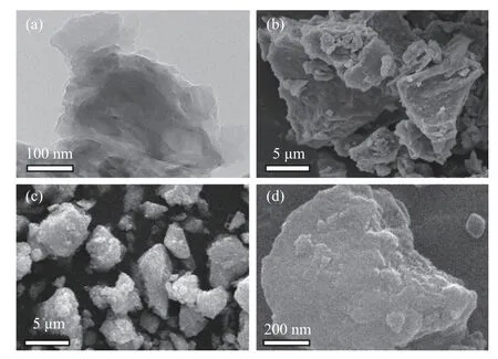
Figure 2 (a) TEM image of C3N4,(b) and (c) are the SEM images of MoS2 and MT-CN-80,(d) local enlarged SEM image of MT-CN-80
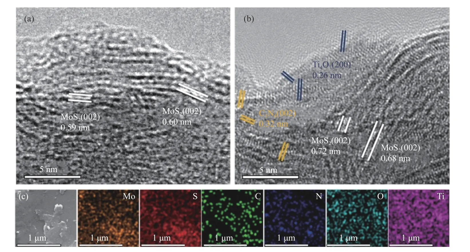
Figure 3 HRTEM images of (a) MoS2 and (b) MT-CN-80,(c) The SEM and elemental mapping images of Mo,S,C,N,O and Ti in MT-CN-80
The structure of C3N4,MoS2and MT-CN-x was revealed by X-ray diffraction patterns (XRD).As shown in Figure 4(a),the C3N4exhibits two distinct diffraction peaks at 13.1° and 27.4°,corresponding to(100) and (002) planes of graphitized carbon nitride.The broad peak at about 21.1° indicates small amount of amorphous carbon in C3N4.The characteristic peaks of MoS2and MT-CN-80 are well matched with that of 2H-MoS2(JCPDS No.37-1492) and the peak of (002)plane of MoS2can be obviously observed to shift from 14.4° to about 9°,which is a feature of 1T-MoS2and marks of the occurrence of the phase transition of MoS2[31,32].The existence of 1T phase provides more active sites and better conductivity for HER.Interestingly,the peak of MT-CN-80 has stronger fluctuations than that of MoS2,which suggests the smaller crystal size and stronger diffuse reflection.As a result,the background noise become stronger which is corresponding to the layer stacking structure with smaller particles in SEM.The sharp peaks in MT-CN-80 correspond to the characteristic peaks of Ti4O7(JCPDS No.50-0787).It is worth noting that only a broad peak at around 21° related to C3N4can be found in the MT-CN-80 which reveals that heat-treated C3N4with a thinner layered structure cannot be detected because it is embedded into the interlayer of MoS2.In addition,the similar XRD patterns of MT-CN-x(Figure 4(b)) show that the change of C3N4content is not sensitive to XRD detection.
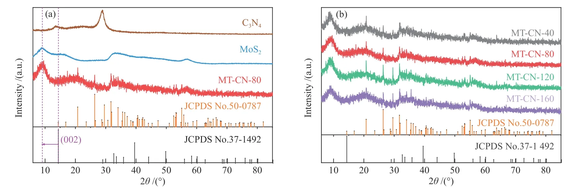
Figure 4 XRD patterns of (a) C3N4,MoS2,MT-CN-80 and (b) MT-CN-x
Raman spectroscopy was performed to determine the domain size and lattice strain of MoS2(Figure 5).Except for the(387 cm−1) and A1g(413 cm−1) modes of 2H-MoS2,peaks at 158,234,292,and 349 cm−1belongs to J1,J2,E1gand J3modes of 1T-MoS2[12,33],which are consistent with the results of XRD analysis.The strong J1,J2and E1gmodes indicate the strain exists in the catalyst.The strain may be derived from surface stress caused by C3N4and Ti4O7anchored on the MoS2nanolayers,leading to the displacement of S and Mo layers and the phase transformation[11,34].The E2gand A1gare sensitive to tensile and compressive stresses.The slight red shift of E2gand A1gof MT-CN-80 indicates that appropriate content of C3N4and Ti4O7can bring stronger tensile strain[35],which promote the dispersion of MoS2and expose more defects and edge sites.The result is consistent with those of SEM and XRD.In addition,due to the electron-phonon coupling,the J1mode also shows blue shift with the increase of electron doping concentration[34],indicating a relatively stronger electron transfer between C3N4and MoS2under the appropriate content of C3N4in MT-CN-80.
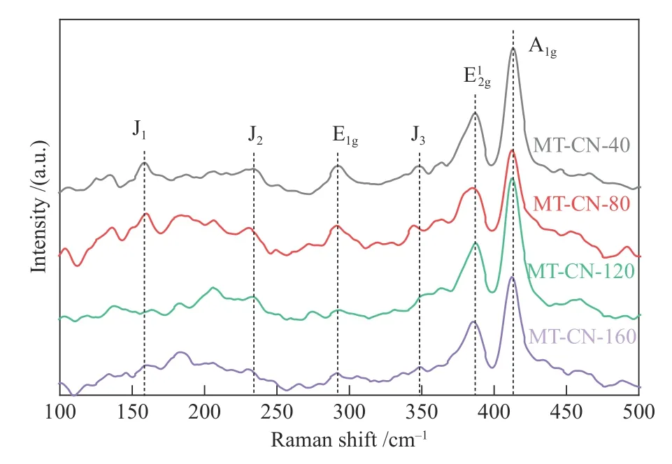
Figure 5 Raman spectra of MT-CN-x

Figure 6 FT-IR patterns of (a) C3N4,(b) MoS2 and MT-CN-x
All samples were characterized by Fourier Transform infrared spectroscopy (FT-IR) to determine the chemical structures.For C3N4(Figure 6(a)),three main absorption regions are detected including the stretching mode of N−H (3198 cm−1),vibration modes of C=N and C−N (1649−1150 cm−1),and stretching mode of triazine unit ring (809 cm−1)[21,36].After combination of MoS2with C3N4and Ti4O7(Figure 6(b)),the absorption band at 1206−1053 and 592 cm−1shift,which may be due to the strong electron interaction between the interfaces of different components,manifesting the transformation of intermolecular chemical bonds[37−39].The signal of C3N4is hardly observed for MT-CN-x.According to the above HRTEM and XRD results,it is probably due to the few amount and the smallest particle size of C3N4after hydrothermal treatment while MoS2and Ti4O7are dominant in the composite catalyst.Only does phase transformation of MoS2from 2H to 1T occur during the hydrothermal process,however,it is beneficial to HER performances.These characterization information indicate that the improvement of HER performances of MT-CN-x composite catalyst is largely ascribed to the interfacial modulation among C3N4,MoS2and Ti4O7components.
2.2 XPS of MoS2 and MT-CN-80
X-ray photoelectron spectroscopy (XPS) were collected to explore the surface chemical composition,valence state and interaction between different components of the catalyst.As shown in Figure 7(a),MT-CN-80 contains Mo,S,C,N,O and Ti,which is consistent with the EDS results.It is worth noting that a small amount of Na from the Mo precursor are kept for MT-CN-80 because they are inserted in the MoS2layers during hydrothermal reaction.

Figure 7 (a) survey spectrum,(b) Mo 3d and (c) S 2p XPS spectra of MoS2 and MT-CN-80,the (d) C 1s,(e) N 1s,(f) O 1s XPS spectra of MT-CN-80 electrocatalyst
In the Mo 3d spectrum (Figure 7(b)),except for the S 2s signal (226.6 eV),the most intensive doublet peaks of pure MoS2at 229.1 and 232.4 eV belong to Mo4+3d5/2and 3d3/2,respectively.The peaks at 234.1 and 236.4 eV correspond to Mo6+in the Mo−O bond due to a slight surface oxidation[40,41].Compared with MoS2,the peaks of Mo 3d shift toward lower binding energy after incorporating C3N4and Ti4O7,indicating that the electronic distribution of MoS2changes.The electron transfer from C3N4and Ti4O7to MoS2may result from the chemical coupling of Mo or S with C3N4and Ti4O7to form interface coordination,which further verifies the conjectures of the shift of the absorption band of FT-IR[42−44].
As shown in Figure 7(c),S 2p spectrum shows the doublet peaks at 162.1 and 163.4 eV belonging to S2−2p3/2and 2p1/2,which are the characteristic peaks of MoS2.Similarly,the peaks of S 2p of MT-CN-80 also shifts to a lower binding energy.This indicates that the coordination mode of MoS2has changed after chemical coupling with C3N4and Ti4O7,which directly leads to an increase in the content of unsaturated sulfur atoms at the bridge () and apical(S2−) ligand of MoS2(164.9 eV)[44−46].Unsaturatedand S2−are highly active sites of HER,which promote the absorption and desorption of hydrogen atoms[44,47].The new peak at 161.1 eV is attributed to the S−O−Ti bond of MT-CN-80,which is related to the strong electronic interaction between MoS2and Ti4O7,in agreement with our previous research[27].As for the peak at 169.0 eV,it might be a characteristic peak of the S4+in,which still exists at the edges of MoS2layer after cleaning[46−48].
In the C 1s XPS spectrum of MT-CN-80 (Figure 7(d)),three characteristic peaks located at 284.6,286.2 and 288.6 eV are assigned to C−C,C−NH2and N−C=N bonds,respectively.In Figure 7(e),the N 1s spectrum of MT-CN-80 can be divided into three subpeaks at 397.3,399.5 and 402.1 eV associated with the pyridine N,pyrrole N and Mo-N group regardless of interference from the Mo 3p signal[21,28,49].The formation of Mo-N coordination indicates the strong electronic interaction between MoS2and C3N4,well confirming the results of Mo 3d.Curve fitting of the O 1s spectrum of MT-CN-80 (Figure 7(f)) reveals six sub-peaks at 530.6,531.2,531.8,532.5,533.5 and 536.7 eV,which are assigned to Ti4+−O,Ti3+−O,Mo6+−O2−,S−O−Ti,Mo−OH bonds and adsorbed H2O,respectively.The Ti3+and Ti4+species indicates that Ti4O7is still stable after hydrothermal process.The S−O−Ti bond formed between MoS2and Ti4O7can not only improve the stability of MT-CN-80,but also promote the electron transfer between the interface.
In one word,the above XPS results corroborate the presence of MoS2,C3N4and Ti4O7,highlighting the contribution of the Mo−N and S−O−Ti coordination structures that improve the electron transfer between the interface in the MT-CN-80 catalyst.
2.3 Catalytic activity
The electrocatalytic activity of MT-CN-80 heterogeneous catalyst was evaluated.For comparison,the performance of as-synthesized C3N4,MoS2,MTCN-0,M-CN-80,Ti4O7and 20% Pt/C were also tested.As shown by linear sweep voltammetry curve (LSV)(Figure 8(a)),the HER currents of C3N4and Ti4O7is negligible,indicating that C3N4and Ti4O7are electrochemically inert.However,MT-CN-80 shows significantly enhanced electrocatalytic activity compared to pure MoS2(overpotential at the current density of 10 mA/cm2= 372 mV),MT-CN-0 (overpotential at the current density of 10 mA/cm2= 288 mV) and M-CN-80(overpotential at the current density of 10 mA/cm2=269 mV) because the LSV curve shifts to a lower overpotential of 251 mV at the current density of 10 mA/cm2,especially at the high potential.Meanwhile,effects of the modification of C3N4and Ti4O7on the catalytic kinetics of MoS2were investigated by the linear portion of a Tafel plot (Figure 8(b)),in which the Tafel slope of MT-CN-80 (54 mV/dec) is much smaller than that of MoS2(125 mV/dec).The decrease of Tafel slope indicates that the addition of C3N4and Ti4O7significantly accelerates the kinetics of electrochemical process.The rate determining step is also converted from hydrogen adsorption process (Volmer reaction) to electrochemical desorption process (Heyrovsky reaction)[50,51].Significantly,in Figure 8(a) and 8(b),the physical mixing of C3N4(MT+ CN-mixed) leads to a decrease in the catalytic performance of MT-CN-0 due to the coverage of the active sites of MT-CN-0 by C3N4.The result further proves that the interface interaction between C3N4and MoS2occurs in the hydrothermal reaction,and the formation of Mo-N bond is crucial to improve the catalytic hydrogen production performance of MT-CN-80.Figure 8(c)summarizes the Tafel slope and current density at high potential (300 mV) of a series of Mo-based electrocatalysts among which MT-CN-80 in this work shows the best performance.
For the catalysts with different contents of C3N4(x =0,40,80,120,160 mg) ,MT-CN-80 has the outstanding HER activity.This may be ascribed to the agglomeration of C3N4and the decrease of the amount of the exposed active sites due to the coverage of too much C3N4.
To understand the enhancement of activity,electrochemical active surface area (ECSA) and electrochemical impedance spectroscopy (EIS) were measured from the perspective of active sites and charge transfer kinetics.The cyclic voltammetry (CV) test was performed at scanning speeds within the potential window of 0.1 to 0.2 V (V vs RHE).In Figure 9(a),the electrochemical double-layer capacitance (Cdl) is calculated by linear fitting of CV curves.Compared with the low Cdlfor pure MoS2(2.24 mF/cm2),the Cdlof MT-CN-80 catalyst increases more than 7 times(16.24 mF/cm2).The ECSA of an electrocatalyst is strongly associated with the number of active sites.ECSA calculated from Cdlin Table 1 shows the greatly enhancement of MT-CN-80,suggesting that the integration of C3N4and Ti4O7with MoS2is beneficial to increase ECSA and create more active sites.MTCN-80 has a rougher surface and thus contains more active sites (Table 1),further explains its superior catalytic properties from the structural level.The increased ECSA and roughness facilitate the penetration/diffusion of electrolyte ions,provide more reaction channels,and promote the interaction between the heterogeneous electrocatalyst and the electrolyte.Thus,the electrochemical kinetics of MT-CN-80 change substantially (supported by the smallest Tafel slope).EIS measurements were performed to study the charge transportation kinetics.As shown in Figure 9(b),charge transfer resistance (Rct) of the MT-CN-80 (148 Ω) is much smaller than that of MoS2(582 Ω),indicating the much easier charge transfer across the interface between MoS2and C3N4/Ti4O7.According to the XPS analysis,the intermolecular chemical bonds of Mo−N and S−O−Ti improve the weak charge transfer of MoS2and accelerate the charge transfer kinetics on the surface of MoS2.
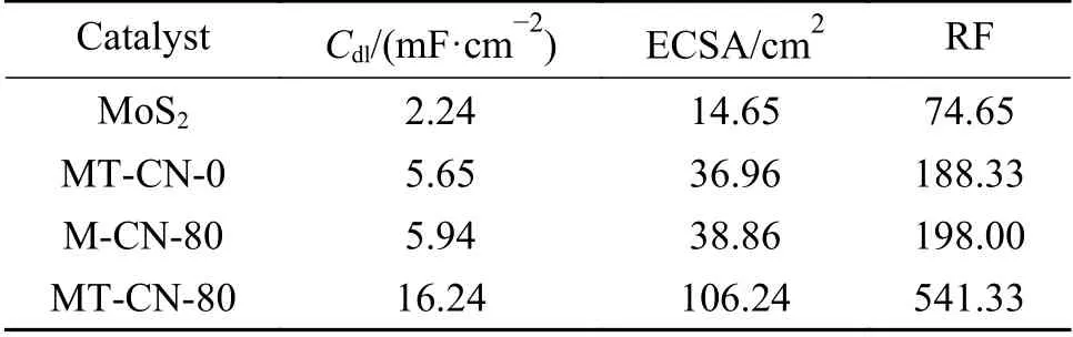
Table 1 Comparison of the double-layer capacitance (Cdl),electrochemical surface areas (ECSA) and roughness (RF)of the as-synthesized catalysts
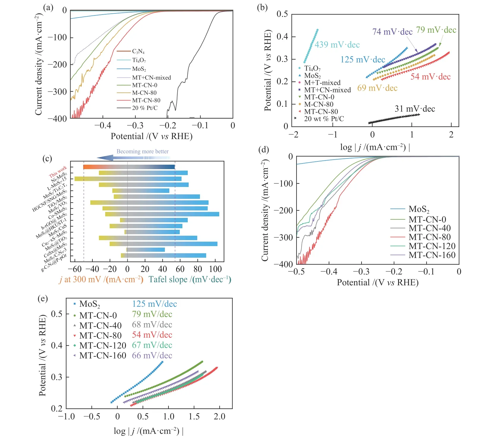
Figure 8 (a) Polarization curves (LSV) and (b) Tafel slopes of various catalysts,(c) Comparison diagram of catalytic performance with Mo-based composite catalyst,(d) Polarization curves (LSV) and (e) Tafel slopes of MoS2 and MT-CN-x

Figure 9 (a) Curves of capacitive currents as function of scan rates,(b) Nyquist plots of various catalysts,(c) Durability test for MT-CN-80 before and after 10000 cycles,(d) current-time curve of MT-CN-80 at an overpotential of 300 mV
The long-term cycling stability of MT-CN-80 was evaluated by the LSV measurement for 10000 cycles.The MT-CN-80 shows an excellent durability with negligible degradation i.e.the overpotential only increased by 9 mV at the current density of 100 mA/cm2(Figure 9(c)).This can be ascribed to the obvious sample shedding after a long period of rotation of the rotating disk electrode.Regarding the chronoamperometry(CA) test (Figure 9(d)),industrial electrolysis of water to produce hydrogen is usually carried out at a high voltage,so a constant and relatively large voltage (300 mV) is applied on MT-CN-80.Moreover,due to the constraints of experimental conditions,the long-term hydrogen production process will consume a large amount of electrolyte,which will cause slow attenuation of current density.Even though,MT-CN-80 can still maintain a stable state of about 50 mA/cm2after about 33 h and the current fluctuation is almost negligible through replacement of fresh electrolyte timely.
2.4 Possible catalytic mechanism of MT-CN-80
Based on the above structural characterization and electrochemical performance evaluation,a possible catalytic mechanism is proposed in Figure 10.At the structural level (Figure 10(a)),MoS2is anchored by the chemically stable Ti4O7while C3N4with a smaller size is embedded in the MoS2layer to widen the layer spacing.This modulates the in-plane and out-of-plane stress of MoS2,resulting in smaller and more dispersed MoS2particles.The introduced defects and upturned edges promotes the transformation of 1T phase with more active sites and improved conductivity beneficial to the electrocatalytic HER process.At the electronic level (Figure 10(b)),C3N4combine with MoS2to construct a graphene-like heterojunction.The strong interface effect between C3N4and MoS2forms a Mo-N coordination structure,which is conducive to the transfer of electrons (supported by XPS).Moreover,Ti4O7is tightly combined with MoS2through S−O−Ti bond and can also promotes the charge transfer.Furthermore,Ti4O7and C3N4with stable chemical properties can stabilize the structure of heterogeneous catalysts especially when chemical bonds formed between the interfaces,which improve the tolerance of MT-CN-80,leading to an excellent durability after a long time of catalytic cyclings.This is crucial particularly for practical industrial applications.
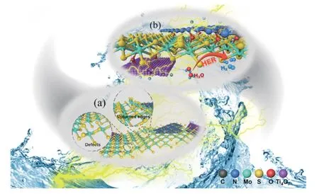
Figure 10 Schematic diagram and possible catalytic mechanisms for MT-CN-80 electrocatalyst
3 Conclusions
The MT-CN-80 heterogeneous catalyst was synthesized by using a simple hydrothermal route through decorating C3N4onto Ti4O7anchored MoS2.Characterization analyses show that the introduction of C3N4and Ti4O7introduces more active sites (such as defects,upturned edges) and promotes the charge transfer between interfaces due to the formation of 1TMoS2,Mo-N and S-O-Ti bonds.These endow the MTCN-80 with a small Tafel slope (54 mV/dec) and a low overpotential (251 mV@10 mA/cm2) in comparison to the pure MoS2and MoS2-Ti4O7catalysts.Moreover,the strong interface effect and coordination between C3N4,Ti4O7and MoS2can also stabilize the catalyst.The cyclic tests highlights the excellent tolerance of the catalyst for practical application.This work reveals the importance of interface effect for heterogeneous structures and provides more insights for the rational design of highly active HER electrocatalysts.