An interfacial self-assembly strategy to fabricate graphitic hollow porous carbon spheres for supercapacitor electrodes
2021-06-18ZHANGXiaohuaGANXinyuLIUBaoshengYANXiaoyanZHAOXinxin
ZHANG Xiao-hua,GAN Xin-yu,LIU Bao-sheng,YAN Xiao-yan,ZHAO Xin-xin
(College of Materials Science and Engineering, Taiyuan University of Science and Technology, Taiyuan 030024, China)
Abstract:Graphitic hollow porous carbon spheres (GHPCSs) have the advantages of a unique cavity structure,high surface area and excellent conductivity,and are promising electrode materials for energy storage.A Fe–tannic acid (TA) framework synthesized using TA as the carbon source and K3 [Fe(C2O4)3] as a complexing agent,was self-assembled onto a melamine foam,which was converted to GHPCSs by carbonization,where the K3 [Fe(C2O4)3] also acts as an activating-graphitizing agent.The outer shell of the asprepared GHPCSs has a large specific surface area,a micropore-dominated structure and excellent electrical conductivity,which ensure a large enough active surface area for charge accumulation and fast ion/electron transport in the partially graphitized carbon framework and pores.The optimum GHPCS has a high capacitance of 332.7 F g−1 at 1 A g−1.An assembled symmetric supercapacitor has a high energy density of 23.7 Wh kg−1 at 459.1 W kg−1 in 1 mol L-1 Na2SO4.In addition,the device has long-term cycling stability with a 92.1% retention rate after 10 000 cycles.This study not only provides an economic and time-saving approach for constructing GHPCSs by a self-assembly method,but also optimizes ion/electron transport in the carbon spheres to give them excellent performance in capacitive energy storage.
Key words:Hollow carbon sphere;Graphitization;Tannic acid;Supercapacitor
1 Introduction
Carbon materials have multiple advantages including abundant sources,outstanding chemical/thermal stability,tunable porosity and environmental friendliness[1,2].They have been considered as promising electrode materials for applications in energy storage devices,such as supercapacitors[3],lithium-ion batteries[4],metal-air batteries[5]and lithium-sulfur batteries[6].Among them,supercapacitors based on carbon electrodes have gained tremendous interests owing to their wide operation temperature region,long cycling lifespan and excellent reversible charge/discharge performance[7].However,the commercial development of carbon-based supercapacitors is limited by the ion/electron kinetic barriers and small energy density (5–8 Wh kg−1)[8].The energy stored in carbon materials greatly depends on their pore structure and electronic conductivity.An excellent pore structure refers to a large effective specific surface area (SBET)and suitable pore size distribution,which can offer abundant active sites for charge accumulation and accelerate ion transport.An excellent electronic conductivity is directly related to the graphitic structure of a carbon material,which can reduce the electron transfer resistance.Thus,it is desirable to fabricate efficient carbon materials with largeSBET,suitable pore size distribution and high graphitization degree.
Hollow carbon spheres (HCSs) comprise of a huge internal cavity and a thin carbon shell,which endow them unique electrochemical properties.Specifically,the hollow structure of HCSs can not only provide abundant surface area for charge accommodation during charge/discharge process,but also accommodate the volume expansion/contraction,prolong cycling stability.Also,the carbon shell with good conductivity can facilitate electron transfer[9,10].However,the compact structure of the carbon shell seriously inhibits the infiltration and transport of electrolyte ions,resulting in a poor capacitive performance.For the purpose of facilitating ion diffusion and increasing effective surface area,pore engineering has been regarded as a promising strategy[11,12].Wang’s group[13]synthesized HCSs by a hard template method.After subsequent KOH activation,the obtained HCSs have a micro/mesoporous shell and theSBETincreases from 669 to 1 290 m2g−1,achieving a large specific capacitance of 303.9 F g−1.Hu et al.[14]fabricated hierarchical porous HCSs by a polymer template method and subsequent polymer blend carbonization.Poly methyl acrylic acid was used as a sacrificing template to realize the porous carbon shell after pyrolysis,and the obtained HCSs achieved an enhanced capacitance behavior.HCSs with a porous outer shell not only shorten the ion transport path to inner cavity,but also significantly increase the number of active sites of interior region in the carbon shell,achieving a much better utilization of carbon materials.
Various porous HCSs are synthesized by template methods,because the inner/outer diameter and porous structure can be easily tailored by different templates[9].However,this method usually relies on multi-step procedures including template preparation and removal,which make the procedure tedious,costly,and even environmentally unfriendly (for example,the use of hazardous chemicals,NaOH,HF,or organic solvent to remove templates)[8,15,16].Comparatively,the self-templating method without using additional templates is a time-saving and economic strategy.In this method,HCSs can be directly synthesized by self-templating or a self-assembly method followed by thermal decomposition treatment[9,17].For example,Wu’s group[17]successfully fabricated HCSs from poly(amic acid) and amphiphilic homopolymer vesicles via a self-assembled method.After carbonization,theSBETof the obtained HCSs is 668.1 m2g−1,while the micropore surface area (Smic) accounts for 23.1%[17].Many researches revealed that the micropores contributed maximally to form electrical double-layers[18,19].Qian et al.[7]synthesized HCSs by crosslinking p-phenylenediacetonitrile with terephthalaldehyde and benzene-1,3,5-tricarbaldehyde.The obtained porous HCSs possess a highSBETof 1 963 m2g−1and aSmicof 1 716 m2g−1.Microporous graphitic HCSs were also prepared by a simple carbonization of melamine-formaldhyde resin spheres synthesized by a self-assembly method[20]. However,few carbon sources are available for self-assembly to synthesize the hollow spherical structure.Recently,renewable,inexpensive biomass-based materials are particularly preferred to be adopted as carbon precursors to achieve sustainable development[21].Therefore,design a straightforward self-assembly route to prepare HCSs using renewable precursors is urgently needed.
In this paper,we report a feasible Fe–tannic acid(TA) complexing strategy and one-step carbonization to fabricate graphitic hollow porous carbon spheres(GHPCSs).Specifically,TA,as the carbon source,offers the advantages of being abundant,non-toxic,cheap,and wide distribution in plant issues[22].K3[Fe(C2O4)3],as the source of metal coordinating sites,can form Fe–TA complexing framework with the ample phenolic hydroxyl groups in TA.Moreover,the degraded products of Fe species and K2C2O4from K3[Fe(C2O4)3] can act as a graphitizing catalyst and an activating agent,respectively.After carbonization,Fe–TA complexing framework was transformed into GHPCSs,characterized by a graphitic porous carbon shell and internal cavity.Compared with the conventional template methods,the present self-assembly method avoids tedious and time-consuming procedures.More importantly,simultaneous activation and graphitization can be achieved by one-step carbonization,endowing GHPCSs with accessible pore surface and good conductivity.
2 Experimental
2.1 Synthesis of GHPCSs
2.0 g of TA and 2.5 g of K3[Fe(C2O4)3]·H2O were dissolved into 20 mL deionized water to form solutions,separately.Then the K3[Fe(C2O4)3] solution was added dropwise into the TA solution under magnetic stirring to form Fe–TA complexing ink.0.15 g melamine foam with a small cube was immersed into the ink for 1 h and then dried at 80 °C for 18 h.The obtained solid mixture was carbonized at a certain temperature (700,750,800 °C) under N2flow for 2 h.Finally,the carbon power was further washed using 3 mol L−1HCl and deionized water for several times to remove Fe species and other inorganic impurities.The obtained product was labeled as GHPCST(whereTstands for the carbonization temperature of 700,750 and 800 °C).
For comparison,the sample synthesized without using a melamine foam was also performed,and the related carbonization temperature is 750 °C.The obtained sample was denoted as a graphitic porous carbon (GPC).
2.2 Materials characterization
Morphologies and structural features of the samples were measured by JSM-6510F (JEOL,Japan)and Tecnai G2 F20 S-Twin (FEI.org,USA) to obtain scanning electron microscopy (SEM) images and transmission electron microscopy (TEM) images,respectively.TheSBET(calculated by Brunauer–Emmett–Teller method) and pore size distributions (evaluated through density functional theory method) were gained based on the N2adsorption–desorption tests using BELSORP-max (MicrotracBEL Japan Inc.).The miniflex 600 diffractometer (Rigaku,Japan) was employed to obtain X-ray diffraction (XRD) patterns.The LabRAM HR 800 spectrometer (HORIBA JobinYvon,France) was applied to obtain Raman spectra.The ESCALAB 250 (Thermo Fisher Scientific,USA) was used to collect X-ray photoelectron spectra (XPS).
2.3 Electrochemical measurement
A CHI760e electrochemical workstation (Shanghai Chenhua Instrument Co.,Ltd.,China) was used to evaluate the electrochemical performance of electrodes.A homogeneous slurry,containing active carbon material (80 wt%,2.4 mg),acetylene black(10 wt%),and polytetrafluoroethylene (10 wt%),was coated on a Ni foam substrate to obtain the working electrode.Three-electrode system was used to assess the performance of carbon electrodes using 6 mol L−1KOH electrolyte.The reference and counter electrodes are Hg/HgO and Pt foil electrode,respectively.As for two-electrode system,the symmetric supercapacitor was prepared by using polypropylene membrane as a separator,6 mol L−1KOH or 1 mol L−1Na2SO4as electrolytes.Two symmetric electrodes have the same mass loading of active materials.
The specific capacitance in the three-electrode system (C,F g–1) and two-electrode system (Csp,F g–1)can be calculated according to the following equations (1) and (2),respectively:
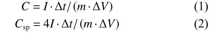
whereI,m,Δtand ΔVdenote the response current (A),the mass of active material (g),the discharge time (s),and the potential window (V),respectively[23].
Energy densityE(Wh Kg–1) of the symmetric supercapacitor was obtained by the equation (3)
whereV(V) refers to the discharging potential.
Power densityP(W Kg–1) of the symmetric supercapacitor was obtained by the equation (4):

3 Results and discussion
3.1 Morphology and structural properties
The synthetic procedure of GHPCSTis illustrated in Fig.1,including Fe–TA complexation and carbonization.TA is an environmentally friendly polyphenol,which can provide numerous binding sites for coordinating with Fe ions to form a stable Fe–TA complex.The complexing effect between Fe ions and TA realizes a uniform dispersion of Fe atoms on the carbon precursor,which is beneficial for the formation of carbon with a graphitic structure.Fe–TA complexing ink has excellent penetrability and adhesion[22],which can be easily attached and uniformly dispersed on the skeleton of melamine foam.During carbonization,the Fe–TA complex can be transformed into a hollow sphere structure with internal void.K3[Fe(C2O4)3] can be decomposed into K2C2O4and FeC2O4(2K3[Fe(C2O4)3] → 3K2C2O4+2FeC2O4+2CO2) under high temperature[23].These two oxalates can be further decomposed to K2CO3(K2C2O4→K2CO3+CO) and FeO (FeC2O4→ FeO+CO+CO2).The former is an effective chemical activating agent,which can corrode carbon skeleton to create pores on the carbon shell.While,the latter can be transformed into Fe3C after a series of reactions,which is an effective intermediate product to transform amorphous carbon into graphitized carbon[24].Moreover,the released gases (CO and CO2) during carbonization can act as pore-forming agents.Thus,K3[Fe(C2O4)3] is not only responsible for the complexation of Fe–TA framework to construct hollow carbon spheres,but also acts as an activating–graphitizing agent to develop a graphitic porous carbon structure.

Fig.1 Scalable fabrication of a Fe–TA complex and its subsequent carbonization to convert into GHPCST.
The morphologies of GHPCSTcarbonized at 700,750 and 800 °C are shown in Fig.2.All carbon samples have a spherical structure (Figs.2a-c),but differ on the surfaces of carbon shells.GHPCS700has a smooth surface (Fig.2a).While,there are a lot of bulges and several macropores on the rough surface of HPGCS750(Fig.2b),which may be caused by the physical activating effects of released gases and etching effect of K2CO3on the carbon shell[25].GHPCS800shows more obvious pores on the surface of the carbon shell in Fig.2c.The difference in the surface morphology of GHPCSTcan be deduced as follows:(i) the activating effect of K3[Fe(C2O4)3] becomes more intense with increasing the carbonization temperature,thus more pores generated on the surface of sphere shell;(ii) the rise of temperature may cause the fusion or collapse of pores,making the pores more obvious[26].The pores on the surface of the carbon shell are beneficial for the penetration of electrolyte ions into inner region,effectively shortening ion transport path,and significantly increasing the number of electroactive sites.The broken carbon sphere in Fig.2c indicates a huge internal cavity in the sphere.During charge/discharge process,the hollow cavity plays a role of“ion-buffering reservoir”,which can effectively shorten the diffusion distance of ions and accommodate the volume change[14].Fig.2d and 2e indicate that the carbon shell exhibits a similar 3D honeycomb-like feature,which not only provides abundant opening channels for effectively accelerating ion transfer rate but also guarantees plentiful active sites for energy storage.It is worth mentioning that melamine foam plays a critical role for the development of the hollow structure.Drying of the Fe–TA ink at 80 °C further promotes the complexation reaction of TA with Fe ions.The melamine foam with extremely high porosity provides supporting skeleton and enough space for the development of Fe–TA spheres.Without using the melamine foam,the Fe–TA framework becomes compact with the water evaporating.As a result,there is no enough space for Fe–TA framework to form a sphere structure.As shown in Fig.2f,GPC without the addition of the melamine foam has an irregular shape.TEM image in Fig.3a shows some mesopores in GHPCS750,which are resulted from the activation effect of K2CO3and elimination of Fe species.High-resolution TEM image (Fig.3b) reveals obvious lattice fringes and worm-like nanopores,indicating a graphitic porous carbon structure.
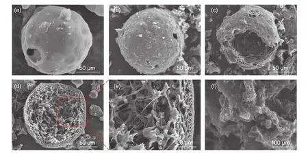
Fig.2 SEM images of all samples:(a) GHPCS700,(b) GHPCS750,(c) GHPCS800,(d) and (e) GHPCS750 and (f) GPC.

Fig.3 (a,b) TEM images of GHPCS750 under different magnifications.
Nitrogen adsorption–desorption isotherms(Fig.4a) of GPC,GHPCS700,and GHPCS750show the typic I/IV isotherm with a slight hysteresis,which is the characteristic of micropores and mesopores.HPGCS800has the typic I isotherm,suggesting its copious micropores. GPC without the addition of the melamine foam has a smallSBETof 1 072.9 m2g−1,and a pore volume (Vtotal) of only 0.51 cm3g−1.With the presence of the melamine foam,theSBETandVtotalof GHPCSTincrease remarkably up to 2 005.7 m2g–1and 0.99 cm3g−1,respectively (Table 1).With the increase of the carbonization temperature,theSBETandVtotalof GHPCSTfollow the trend of GHPCS700(2 005.7 m2g–1,0.99 cm3g−1) > GHPCS750(1 541.8 m2g–1,0.70 cm3g−1) > GHPCS800(1 250.8 m2g–1,0.58 cm3g−1).This phenomenon is caused by the pore collapse and even disappearance of partial micropores at high temperature[26].The pore size distribution curves of GPC and GHPCSTin Fig.4b demonstrate a microporedominated porous structure[27],which originates from the pyrolysis of TA and activation effect of K3[Fe(C2O4)3].The micropore sizes of GHPCSTare concentrated at~0.78 nm,which is close to the optimized ion-accessible micropores[25].Notably,theSmicof GHPCS750accounts for 74.4% ofSBET.Many researchers proved that micropores play a more important role in charge accommodation and enhanced capacitance[28,29].Compared with template methods to prepare hollow carbon spheres,the Fe–TA complexing framework strategy combined with K3[Fe(C2O4)3] activation does not only simplify the process and save energy consumption,but also ensure a largeSBETand a high content of the micropore structure.
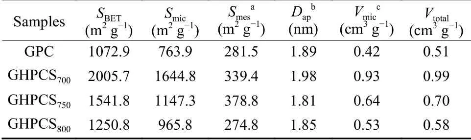
Table 1 The porosity properties of GPC and GHPCST.
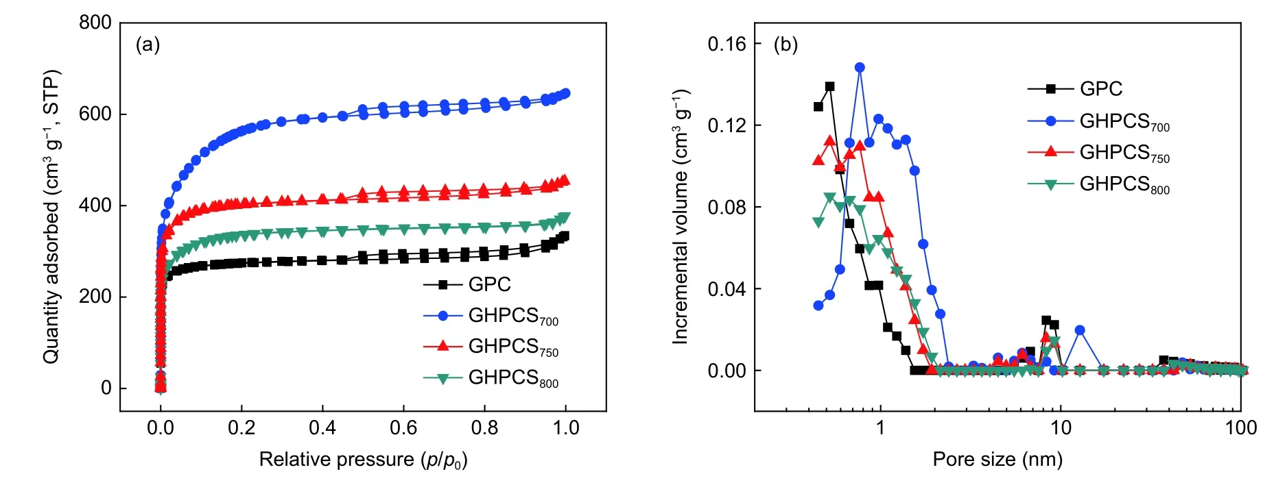
Fig.4 (a) Nitrogen adsorption–desorption isotherms of GPC and GHPCST,(b) pore size distribution curves of GPC and GHPCST.
Apart from a largeSBETand suitable pore structure,the partially graphitized carbon structure with excellent conductivity can be easily achieved by this approach.The XRD patterns (Fig.5a) show that GPC,GHPCS700,and GHPCS750possess a broad hump at 2θ~20–30° for the amorphous carbon framework and a weak diffraction peak at 2θ=43.4° for the (101) plane of the graphitic structure (JCPDS No.41-1487)[30].GHPCS800has a better crystallinity with a distinct and sharp peak for the (002) plane of graphite carbon at 2θ=26.4°,suggesting a more perfect and ordered graphitic structure at higher temperature,compared with other samples[31].A higher intensity at low-angle scatter suggests a larger number of micropores[23].Raman spectra of all samples (Fig.5b) present two distinct bands,Gband (1 585 cm–1) for graphitic carbon andDband (1 335 cm–1) for amorphous carbon[32].The intensity ratioIG/IDvalues of GHPCS700,GHPCS750,and GHPCS800are 0.97,1.05 and 1.06,respectively,indicating an increased graphitization degree with the carbonization temperature[25].The partially graphitic carbon structure with an appropriate amount of defects and disorders is characterized by excellent conductivity and developed pore structure,benefiting for electron/ion transport and energy storage.
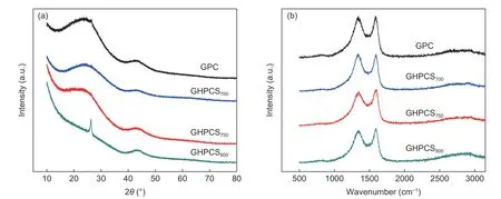
Fig.5 (a) XRD patterns of GPC and GHPCST,(b) Raman spectra of GPC and GHPCST.
XPS spectrum of GHPCS750in Fig.6a presents two distinct peaks of C 1s (~284.8 eV) and O 1s(~533.3 eV),as well as an inconspicuous peak of N 1s (~400.4 eV).The contents of C,O,N are calculated to be 89.43%,7.84% and 2.73%,respectively.The high content of O comes from carbon source(TA) and the small amount of N originates from the melamine foam.The deconvoluted C 1s spectrum(Fig.6b) contains four peaks at 284.5,285.0,286.1 and 288.6 eV,representing sp2-bonded carbon,sp3-bonded carbon,C―O and C=O,respectively.The deconvoluted O 1s spectrum in Fig.6c displays four characteristic peaks,representing O=C―OH(534.3 eV),C―O―C (533.4 eV),C―OH (532.4 eV),and C=O (531.3 eV),respectively[33].The presence of these oxygen-containing groups can enhance the surface wettability of electrodes,benefiting for ion storage during charge/discharge process.
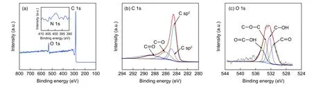
Fig.6 (a) XPS survey of GHPCS750,high resolution XPS spectra of (b) C 1s and (c) O 1s.
3.2 Electrochemical performance
Fig.7a presents the cyclic voltammetry (CV)curves of GPC and GHPCSTat 10 mV s–1.All CV curves of GHPCSTexhibit larger curve areas than that of GPC,due to their higherSBETof GHPCSTthat provides abundant active sites for charge accumulation.The disordered rectangular shape appeared at−0.8–1.0 V and −0.1–0 V could be attributed to the limited ion transport and adsorption into irregular micropores and subnanometer pores with narrow bottlenecks[31].Fig.7b presents the CV curves of GHPCS750at different scan rates.The disorder shape at a higher scan rate is attributed to the insufficient time for ion diffusion and deficient contact to electrode surface[34].The typical galvanostatic charge–discharge (GCD)curves of GPC and GHPCSTwith a symmetrical shape at 1 A g–1imply a favorable electric double-layer capacitance characteristic (Fig.7c).The GCD curve of GHPCS750exhibits the longest discharge time,meaning the highest capacitance.Although,GHPCS700has the largestSBETvalue among all samples and the content ofSmicis up to 82.0%,the low graphitization degree limits electron transfer,resulting in a poor electrochemical performance.The micropore sizes of samples are mainly distributed around 0.46–0.86 nm,which enable the solvated ions OH–(0.30 nm) and K+(0.33 nm) to enter into small pores,resulting in a high capacitance[35,36].Specific capacitances of all electrodes gradually decrease with the increase of current densities (Fig.7d),originating from the insufficient diffusion of ions into inner pores in a relatively short time[37].GHPCS750possesses the largest specific capacitance of 332.7 F g–1at 1 A g–1,outperforming those of GPC (298.7 F g–1),GHPCS700(308.1 F g–1) and GHPCS800(282.4 F g–1).Moreover,this value is comparable and even superior to those of reported carbon spheres (Table 2).This could be attributed to the porous carbon shell,large surface area,and high graphitization degree of GHPCS750,which allow fast ion diffusion,large ion storage and rapid charge transfer.A high graphitization degree is important for achieving excellent rate performance.GHPCS700has a specific capacitance of 217.5 F g–1at 30 A g–1,indicating a 70.6% capacitance retention when the current density increases from 1 to 30 A g–1.Notably,GHPCS750maintains 244.5 F g–1at 30 A g–1,corresponding to a 73.5% capacitance retention,and GHPCS800achieves a remarkable retention of 76.8% due to its high graphitization degree.GHPCS750shows a 97.5% capacitance retention after 10 000 cycles (Fig.7e).Compared with the first CV curve,CV curve tested after 10 000 cycles still maintains a similar shape without an obvious distortion,which demonstrates its desirable cycling performance.
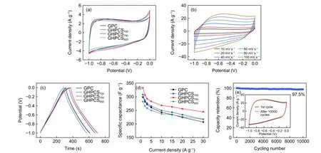
Fig.7 (a) CV curves of GPC and GHPCST at 10 mV s–1,(b) CV curves of GHPCS750 at 10~100 mV s–1,(c) GCD curves of GPC and GHPCST at a current density of 1 A g–1,(d) specific capacitances of all electrodes and (e) cycling stability of GHPCS750 at 100 mV s–1 after 10 000 cycles.
GHPCS750was assembled into a symmetric supercapacitor using 6 mol L−1KOH electrolyte.The CV curves of GHPCS750//GHPCS750(Fig.8a) under various scan rates show nearly identical and rectangular shapes,reflecting a remarkable rate performance and an outstanding double-electrode layer capacitive behavior.The GCD curves (Fig.8b) exhibit the typical triangular profiles at different current densities and theIRdrop at 10 A g–1is only 0.14 V,suggesting a low internal resistance.The specific capacitance of GHPCS750//GHPCS750is 270.5 F g–1at 0.5 A g–1,and it maintains 219.7 F g–1at 10 A g–1,which indicates a 81.2% rate capability when the current density is increased by 20 times.This good rate capability is resulted from the buffering effect of internal cavity space,easy ion diffusion into pore channels,and fast transfer of charge on the conductive network.
Supercapacitor GHPCS750//GHPCS750was further measured with 1 mol L−1Na2SO4electrolyte due to its low concentrations of H+and OH–,allowing a high-stability voltage window.Fig.8c shows a set of CV curves at 40 mV s–1with increasing voltage windows.There is no obvious increase of the anodic current in CV curves when voltage window increases to 1.8 V[40].The quasi-rectangular shapes of CV curves(Fig.8d) and the isosceles triangle-shapes of GCD curves (Fig.8e) at the voltage window of 1.8 V further demonstrate an ideal capacitive characteristic.At a high current density,it appears a smallIRdrop owing to the difficulty of ion transport into inner pore network.The specific capacitance of GHPCS750//GHPCS750in Na2SO4electrolyte is 211.2 F g–1at 0.5 A g–1,and it maintains 144.3 F g–1at 10 A g–1,corresponding to a 68.3% rate capability,which is smaller than that in KOH electrolyte.The cycling stability of GHPCS750//GHPCS750tested in 1 mol L−1Na2SO4electrolyte (Fig.8f) displays a 92.1% retention after 10 000 cycles.This value is comparable to those of reported carbon spheres[7,13,14,16,38,39](Table 2).
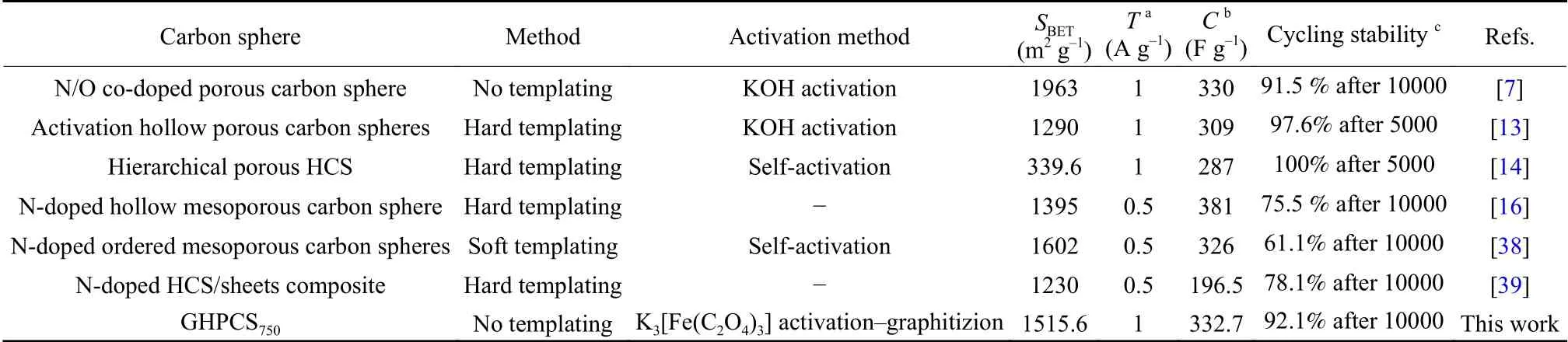
Table 2 Performance comparison of various carbon spheres.
Fig.8g displays the Ragone plots of GHPCS750//GHPCS750supercapacitor.When the electrolyte is 6 mol L−1KOH,the energy density of GHPCS750//GH-PCS750is 9.4 Wh kg–1at a power density of 252.2 W kg–1.Impressively,a large potential window(1.8 V) in 1 mol L−1Na2SO4affords a maximum energy density of 23.7 Wh kg–1when power density is 459.1 W kg–1,and it retains 20.5 Wh kg–1at 3 035.0 W kg–1.which is comparable to or even exceeds some reported supercapacitors using carbon materials as electrodes[41–47].The outstanding capacitive performance and superior cycling stability of GHPCS750are attributed to the following advantages:(i) the pores on the outer shell act as open channels to facilitate ion diffusion and offer abundant electroactive sites for energy storage;(ii) the high graphitization degree and the high conductivity network of the carbon shell promote fast electron transfer to realize efficient utilization of carbon space;(iii) the unique hollow cavity can provide a buffer space and effectively relieve the volume expansion/contraction,thus improving the durability.
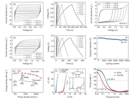
Fig.8 Electrochemical characteristics of GHPCS750//GHPCS750:(a) CV curves and (b) GCD curves in 6 mol L−1 KOH electrolyte,(c) CV curves with a potential window of 1.0–2.0 V in 1 mol L−1 Na2SO4,(d) CV curves at scan rates of 10–100 mV s–1 with 1.8 V in 1 mol L−1 Na2SO4,(e) GCD curves in 1 mol L−1 Na2SO4,(f) cycling stability for 10 000 cycles in 1 mol L−1 Na2SO4,(g) Ragone plots,(h) Nyquist plots,and (i) Bode phase angle plots of GHPCS750//GHPCS750 tested in different electrolytes.
The ion and electron transport kinetics were measured by electrochemical impedance spectroscopy (EIS).Nyquist plots (Fig.8h) of GHPCS750//GHPCS750show the typical double-layer capacitive behavior with a semicircle at high frequency segment and a nearly perpendicular line at low frequency segment.The equivalent circuit model fitted by the Zsim-Demo software is displayed in the inset.The equivalent series resistance (Rs) of GHPCS750//GHPCS750in KOH electrolyte is 1.0 Ω and the charge transfer resistance (Rct) is 0.25 Ω.In Na2SO4electrolyte,the values ofRsandRctare 4.3 Ω and 1.6 Ω,respectively,which are obviously larger than those ofRsandRctin KOH electrolyte.Such differences are related to the ionic mobility (OH−> SO42−> K+> Na+) and the conductivity of electrolytes (KOH (aq.) > Na2SO4(aq.))[48].Fig.8i shows Bode phase angle plots of GHPCS750//GHPCS750.At the phase angle of–45°,the frequenciesf0for KOH electrolyte and Na2SO4electrolyte are 0.35 Hz and 0.07 Hz,respectively.The corresponding time constantsτ0are 2.88 s (KOH electrolyte) and 13.77 s (Na2SO4electrolyte).The low time constant indicates rapid frequency response,suggesting fast ion transport.
4 Conclusion
A simple and novel Fe–TA framework strategy combined with one-step carbonization was employed to synthesize GHPCSs,based on the complexation of TA with Fe ions and the activation–graphitization effect of K3[Fe(C2O4)3].In addition to possessing a porous carbon shell and a huge internal cavity,the obtained carbon spheres have high specific surface area,micropore-dominated structure,and high graphitization degree,which allow the carbon spheres for achieving fast and effective mass diffusion and ion/electron transport.These superiorities endow GHPCS750with a high specific capacitance (332.7 F g–1at 1 A g–1) and excellent rate capability.More importantly,the symmetric supercapacitor in Na2SO4electrolyte processes a maximum energy density of 23.7 Wh kg–1at 459.1 W kg–1,and it has a 92.1% capacitance retention after 10 000 cycles.This study not only provides an economic and sustainable self-assembly strategy to fabricate GHPCSs for high-performance supercapacitor,but also puts a way to optimize ion/electron transport in carbon spheres.
Acknowledgements
The Scientific and Technological Innovation Programs of Higher Education Institutions in Shanxi (No.2020L0330),the Award Fund for Outstanding Doctors in Shanxi Province (No.20202075) and the Doctor Funds of Taiyuan University of Science and Technology (No.20192054).
杂志排行
新型炭材料的其它文章
- 碳纳米管对炭纤维/聚碳酸酯复合材料界面结合性能的影响
- Near-infrared emission carbon dots for bio-imaging applications
- Carbon quantum dots:Synthesis and correlation of luminescence behavior with microstructure
- Synthesis of size-controlled carbon microspheres from resorcinol/formaldehyde for high electrochemical performance
- The electrochemical behavior of nitrogen-doped carbon nanofibers derived from a polyacrylonitrile precursor in lithium sulfur batteries
- Boron and nitrogen co-doped carbon dots for boosting electrocatalytic oxygen reduction