Automated Silicon-Substrate Ultra-Microtome for Automating the Collection of Brain Sections in Array Tomography
2021-04-22LongChengSeniorMemberIEEEWeizhouLiuChaoZhouYongxiangZouandZengGuangHouFellowIEEE
Long Cheng, Senior Member, IEEE, Weizhou Liu, Chao Zhou, Yongxiang Zou, and Zeng-Guang Hou, Fellow, IEEE
Abstract—Understanding the structure and working principle of brain neural networks requires three-dimensional reconstruction of brain tissue samples using array tomography method. In order to improve the reconstruction performance, the sequence of brain sections should be collected with silicon wafers for subsequent electron microscopic imaging. However, the current collection of brain sections based on silicon substrate involve mainly manual collection, which requires the involvement of automation techniques to increase collection efficiency. This paper presents the design of an automatic collection device for brain sections. First, a novel mechanism based on circular silicon substrates is proposed for collection of brain sections; second, an automatic collection system based on microscopic object detection and feedback control strategy is proposed. Experimental results verify the function of the proposed collection device. Three objects(brain section, left baffle, right baffle) can be detected from microscopic images by the proposed detection method. Collection efficiency can be further improved with position feedback of brain sections well. It has been experimentally verified that the proposed device can well fulfill the task of automatic collection of brain sections. With the help of the proposed automatic collection device, human operators can be partially liberated from the tedious manual collection process and collection efficiency can be improved.
I. INTRODUCTION
THE human brain is a complex organ that is formed by a large number of neurons, which is the most complex research object in the current scientific community [1].Analyzing of brain functional neural networks helps to diagnose and treat brain diseases, and is of important clinical significance in the field of human health [2]. At the same time, the exploration of brain information expressions and information processing principles is helpful to promote the progress of neuroscience-inspired artificial intelligence research [3]. The understanding and analysis of brain tissue structure by neuroanatomy and histology is a basic part of brain science research [4], [5].
In order to obtain the fine microscopic nervous structure of brain, array tomography is used for high-precision threedimensional reconstruction of brain tissue samples [6], [7].The implementation of array tomography first involves cutting the brain tissue samples into serial brain sections by using an ultra-microtome loaded with a knife boat, then collecting the brain sections floating on the surface of the knife boat, and finally send them to the scanning electron microscope (SEM)for subsequent imaging and 3D reconstruction [8]. To improve 3D reconstruction performance of neuronal connections in the brain, the sequence of brain sections should be collected by a silicon substrates with excellent surface characteristics. Fig.1 shows the process of an operator collecting brain sections using silicon substrate. In this manual collection process, the operator is required to observe the location of brain sections by using the microscope. At the same time, the operator needs to operate a tweezer and an eyelash pencil to collect the brain sections onto the silicon substrate. It is obvious that the manual collection of brain sections requires operators to possess a very high professional literacy, and also consumes considerable time and energy. A natural way of overcoming this limitation is to employ the automation technique using a robot [9] to improve the collection effectiveness.

Fig.1. Entire manual collection process of brain sections: (a) The operator observes the brain sections under a microscope; (b) The slicing device of ultra-microtome; (c) Manual collection process; (d) The brain sections collected on the silicon substrate.
In the literature, some devices for assisting operators to collect brain sections have been proposed. Horstmann et al.[10] proposed a custom-built position device. This device completely imitates the action of the operator holding the silicon substrate, which can reduce the difficulty collecting the brain sections. Spomer et al. [11] proposed a 7 DOF substrate holder which could assist an operator in holding and adjusting the silicon substrate to collect brain sections. Wacker et al.[12] used this device to assist operators in collecting zebrafish tissue sections and create a three-dimensional reconstruction of zebrafish nervous system. Koike et al. [13] proposed a solid substrate lifting device which has a fishing line capable of lifting the collection substrate up from the liquid in the knife boat. It should be noted that the aforementioned devices are only designed to hold the collection substrates for relieving the workload applied to the operator. Burel et al. [14]proposed a novel modified knife boat which has a drainage hole at the bottom; by placing the silicon substrate at the bottom of the knife boat in advance, the brain sections floating on the liquid surface can be collected after drainage process.Koestinger et al. [15 ] proposed a novel magnetic section collection method based on the modified knife boat, which could further reduce the difficulty of section collection. Lee et al.[16] introduced a semi-automatic collection device (LASSO).Operators could use an Xbox joystick to remotely control the motor-driven platform to collect sections, and it takes about 43s to collect a single section by using LASSO [16].However, the efficiency of the section collection is still very low using the aforementioned auxiliary devices. Furthermore,operators are still intensively involved in the collection process. In some practical applications of array tomography,the required number of brain sections is relatively large (e.g.,in [13], the three-dimensional observation of axon and mitochondria of single cell of rat needs 56 brain sections; in [15], 512 sections of male zebra finch were used to inspect their neurons), which makes the improvement of the collection automation level a necessity.
In order to achieve automatic collection of brain sections,Hayworth et al. [17] proposed a thick-sectioning prototype lathe-microtome. This device buries multiple brain samples in the periphery of a cylindrical resin and collects the brain sections with tape substrates. Hayworth et al. proposed an improved device: an automated tape-substrate ultramicrotome (ATUM) based on the aforementioned device.Hayworth et al. [18 ] proposed an automated electron microscope imaging toolkit (WaferMapper) for the ATUM.The ATUM greatly improves the collection efficiency of brain sections, and many studies regarding the array tomography are conducted based on the ATUM [19]–[21]. However, because of the undesirable conductivity of the tape substrate adopted by ATUM, the charge accumulation effect worsens the quality of subsequent electron microscopic imaging, making the follow-up operation of ATUM cumbersome. For example, the tape substrate needs to be bonded to silicon wafer with conductive adhesive and coated with conductive film. Smith[22] proposed an automatic collection device (ArrayBot)which imitates manual collection, however, the ArrayBot is designed for optical imaging and the detailed implementation of ArrayBot has not been given.
Considering the above observations, there are still some limitations in existing automatic collection devices for brain sections. This paper is devoted to the development of a silicon-substrate automatic collection device for brain sections, which aims at guaranteeing the collection efficiency and the quality of subsequent electron microscopic imaging of brain sections.
In order to partially reduce the workload of the operators in the collection process, an autonomous decision-making algorithm based on microscopic object detection needs to be designed. An object detection algorithm is used to obtain the position information of foreground objects (e.g., brain sections) in input images, which has been well studied in the biomedical engineering field [23]–[25]. From the point of view of the feature extraction, there are two main types of object detection methods: the traditional object detection methods based on manually designed features [26] and the object detection methods based on the deep learning [27].
Traditional methods based on manually designed features are driven by expert knowledge and experience. Among them,the single feature extraction method includes histogram of oriented gradient [28], scale-invariant feature transform [29],local binary patterns [30], etc. By fusing different types of features, more expressive image features can be obtained,such as MultiFtr [31] and deformable part-based model methods [32]. However, using these methods may lead to the introduction of a priori hypothesis into the designed detection model or simplification of the real scene.
At present, in the field of the image object detection, the methods based on deep learning achieve better detection results than that of traditional detection methods [33]–[35].Object detection methods based on deep learning are mainly divided into the two-step detection methods based on region proposals and the one-step detection methods without region proposals [36]. For two-step detection methods, the representative work includes region-based convolutional neural networks (R-CNN) [37], and its improved versions, fast R-CNN [38] and faster R-CNN [39]. However, two-step detection methods have a bottleneck in their testing speed,which makes it difficult for them to deal with real-time tasks.The one-step detection methods such as you only look once(YOLO) [40] and single shot MultiBox detector (SSD) [41]can improve detection speed to a certain extent. In the task of microscopic object detection, Hung and Carpenter [42] used the faster R-CNN detection method to locate the cells in microscopic images. Lo et al. [43] realized the detection of glomeruli in microscopic images by using the faster R-CNN detection method. One-step detection methods are often used when there are follow-up real-time control tasks, for example,Dong et al. [44] used the YOLO method to detect the location of nematodes in a microscopic field of vision in real time, and create a three-degree-of-freedom micro-displacement platform to track nematodes based on the detection results. Some deep neural network methods used to detect single-category targets(brain section) in microscopic images have also been proposed in the author’s previous work, which is also a prerequisite for subsequent control tasks [45], [46].
Inspired by the above observation, this paper proposes an SSD-based detection algorithm to detect brain sections and left/right baffles. By using the detected positions of brain sections, the real-time collection state can be obtained and used to design the feedback control algorithm to control the rotation ratio of the collection device. To summarize, the paper’s contributions lie in the following two areas: 1) a novel device (automated silicon-substrate ultra-microtome (ASUM))for automatically collecting brain sections is proposed, which directly utilizes the silicon wafer to collect brain sections for satisfactory imaging quality; 2) to increase collection efficiency, an automatic control system based on the brain section detection is implemented, and the number of collected brain sections by the automatic control system is larger than the one obtained using the open-loop control mode.Experiments have been conducted to verify the effectiveness of the proposed ASUM. Compared to existing manual/assisting collection, the proposed ASUM can reduce the collection skill requirement of the operator, and the interventions the operator must perform are less demanding than using existing assisting devices. Compared to the ATUM, the proposed ASUM can adjust the collection speed according to the real collection state. In addition, the proposed ASUM directly uses a silicon wafer as the collection substrate. As a result, the complicated follow-up operation required by ATUM can be avoided.
This paper is organized as follows. The overview of the mechanical design of the ASUM is given in Section II.Section III describes the proposed automatic collection system for the ASUM. Section IV reports the experimental results based on the ASUM and shows the microscopic object detection results and collection results of brain sections.Section V discusses the limitations of the current ASUM prototype. Finally, Section VI concludes this paper with final remarks and provides possible for the future works.
II. MECHANICAL DESIGN OF THE ASUM
Silicon substrates have outstanding surface properties in the section collection and electron microscopic imaging, so a novel idea of automatic collection of brain sections based on the circular silicon substrate is proposed. Using a collection idea, the circular silicon wafer driven by a rotary motor needs to be tilted into the knife boat with baffles. With the continuous slicing of brain tissue samples, the brain sections move towards the silicon wafer on the water surface along the baffles. The automatic collection system of brain sections automatically detects the moving state of brain sections by using the charge-coupled device (CCD) camera of the microscope in order to control the silicon wafer to absorb the brain sections at an appropriate rotating speed. ASUM is designed based on the aforementioned collection idea. Fig.2 shows the mechanical design of the proposed ASUM, and Fig.3 shows the ASUM placed in the actual experimental environment. The brain sections collected by the ASUM are arranged on silicon wafers in an orderly manner, which can facilitate the secondary imaging and post-dyeing. In addition,the collected brain sections can be directly sent to the electron microscope for imaging without a follow-up processes such as conductive film plating. Hence the tedious post-operation flow of the ATUM can be avoided.

Fig.2. Mechanical design scheme of the proposed ASUM.

Fig.3. Physical diagram of the proposed ASUM: (a) The ASUM and its experimental platform; (b) The detailed structure of the ASUM.
The mechanical structure of the ASUM includes the position adjusting platform, silicon wafer rotating mechanism,and knife boat with baffles.
The position adjusting platform is used to precisely adjust the position and tilt angle of the silicon wafer. As shown in Fig.4, the position adjusting platform includes the height adjustment mechanism, supporting base, angle adjustment mechanism and position fine-tuning platform. The height adjustment mechanism is used to adjust the height of the supporting base and other equipments on the supporting base,which allows the ASUM to be installed independently from the ultra-microtome so that it can adapt to different types of slicing platforms. The angle adjustment mechanism is used to adjust the silicon wafer to an appropriate inclination angle. In the installation of the ASUM, the outer ring part of the silicon wafer should be placed under the baffles of the knife boat. At the same time, a predesigned gap (usually the width of the brain section) between the silicon wafer and the baffles should be maintained, which can be achieved by the position finetuning platform (piezoelectric ceramic positioning device (PI P-611.3, Germany)).

Fig.4. Mechanical design scheme of the position adjusting platform.
The silicon wafer rotating mechanism is used to drive the silicon wafer to collect brain sections. The silicon wafer rotation mechanism, shown in Fig.5 , includes the motor loader, rotary motor, fixed plate, T-bevel gear, bevel gear shaft, and silicon wafer. The motor loader fixed on the piezoelectric ceramic positioning platform is used to load the rotary motor (Faulhaber 3564K024B, Germany) with the fixed plate. The T-shaped bevel gear is fixed on the shaft of the rotary motor, and the T-shaped bevel gear meshes with the bevel gear shaft. The laser-processed single-throw singlecrystal silicon wafers are used as the collection substrates. It is necessary to hydrophilize the silicon wafer by a plasma processor (Schwarze PI, China) such that the silicon wafer has the suitable hydrophilicity of adsorbing brain sections floating on the water surface.

Fig.5. Mechanical design scheme of the silicon wafer rotating mechanism.
The knife boat with baffles is used to store brain sections in cooperation with the ultra-microtome, while limiting the orderly advancement of brain sections between two baffles of the knife boat. As shown in Fig.6(a), the knife boat with baffles includes the section knife, section knife holder, cavity of knife boat, left baffle and right baffle. The epoxy resin adhesive, which has a desirable waterproof properties, is used to bond the section knife and the section knife holder. As shown in Fig.6(b), two through-holes in the cavity of knife boat are used to fix the left and right baffles. Two throughholes have such a certain transverse width that the spacing between two baffles can be adapted to brain tissue samples of different block sizes. The designed knife boat with baffles ensures that the brain sections move in an orderly fashion onto the silicon wafer.

Fig.6. Designed knife boat with two baffles: (a) Mechanical design scheme of the knife boat with baffles; (b) The detailed structure of the knife boat with baffles; (c) The knife boat with baffles installed on the ultra-microtome.
The preparation and collection process of brain sections based on the proposed ASUM are shown in Fig.7.

Fig.7. Procedure of the preparation and collection of brain sections based on the ASUM.
Based on the proposed ASUM, the open-loop collection of brain sections can be realized with the help of operators.During the open-loop collection process, the operator needs to set a suitable constant rotation speed for the silicon wafer, and to manually start and stop the collection process. In addition,the moving speed of brain sections in the collection area usually changes because the water area between two baffles is usually time-varying. In this case, if the silicon wafer continues to rotate at a pre-set constant speed, it leads to the case where the brain sections may be sparsely collected on the silicon wafer, which results in a waste of collection space on the silicon wafer.

Fig.8. Illustration of the open-loop collection of brain sections based on the ASUM.
To realize the automatic collection of brain sections and improve the space utilization of the silicon wafer, it is necessary to monitor the collection progress in real time and provide feedback of the real-time collection state to the automatic collection system to achieve closed-loop collection.In the manual collection process, the operator observes the collection of brain sections through the microscope (Leica M80, Germany) on the ultra-microtome. In order to imitate the above-mentioned artificial observation of the collection state, the real-time microscopic image in the field of vision of the microscope can be obtained by using a CCD camera(Leica IC90E, Germany) installed on the ultra-microtome, and the collection state of brain sections can be determined by the microscopic image processing algorithm introduced in Section III.
III. AUTOMATIC COLLECTION SYSTEM FOR THE ASUM
In order to design an automatic collection system for the proposed ASUM prototype, the microscopic object detection method based on the deep convolution neural network is studied first. Then, based on the microscopic object detection results, the automatic control strategy is proposed to adjust the ASUM to the appropriate working state. Finally, a graphical end-user interface is designed.
A. Microscopic Object Detection
Considering the real-time requirement of the microscopic object detection task, the one-stage detection algorithm (SSD)is adopted in this paper. The SSD algorithm is based on a feed-forward deep convolution neural network that predicts the position information of foreground objects in input images. And the SSD is an algorithm which has a balance between the detection speed and the detection accuracy because SSD does not require the region proposal process in two-stage detection methods like faster R-CNN. Hence, SSD has a faster detection speed than that of faster RCNN. The network architecture and the overall work-flow of the SSD are shown in Fig.8.
The employed SSD network architecture consists of a basic network and an auxiliary structure. The basic network is based on a standard VGG-16 network1VGG16 is one popular and effective deep learning method for the image classification. VGG16 includes 16 hidden layers (13 convolution layers and 3 fully connected layers). The size of the convolution kernel ( 3×3) and the size of the pooling (2×2) are set to be the same for the entire VGG16 network.without any classification layer, and the auxiliary structure contains several multi-scale feature layers whose sizes decrease sequently. At the beginning of the detection process, the input image needs to be resized to 300×300. Then the base network is used to extract feature maps from the input image, and the auxiliary structure is used to extract feature maps at different scales,which allows predictions of objects at multiple scales. Six feature maps at different scales are selected for prediction, i.e.,Conv4, Conv7, Conv8, Conv9, Conv10 and Conv11. It should be noted that the aforementioned feature maps usually refer to the feature maps generated by the corresponding last feature layer. At each selected feature map, a fixed set of default boxes are associated with each feature map cell, and convolutional predictors are used to produce the shape offset relative to default boxes and scores for possible foreground objects. One of the advantages of SSD is the use of multiscale feature maps. The larger feature map at the bottom detects relatively small objects, while the smaller feature map at the top is responsible for detecting large targets, which enables the detection network to detect objects of multiple scales.
In the training process, the annotated ground truth information needs to be matched to a specific output of the convolutional detector, which leads to the loss function and the end-to-end back-propagation training algorithm. The training objective of SSD includes two loss functions: the localization loss function and the confidence loss function.The localization loss function is defined in the following smooth L1form, which is originally proposed in [38]


In the training stage, there exists the sample imbalance issue. The default boxes in the “Neg” set are defined as the negative category samples, and the default boxes in the “Pos”set are regarded as the positive category samples. Even if every ground truth box has several matched default boxes, the number of ground truth boxes is still insufficient, which causes the number of positive samples to be far larger than the number of negative samples. To solve this issue, the hard negative mining method is adopted. The way to realize the hard negative mining is to select the default boxes with smaller confidence errors than predicted to be in the “Neg”category. These default boxes are then ranked from small to large according to their confidence errors. After that, the top-k default boxes are regarded as negative samples for training,where the ratio between the negative samples and positives samples should be less than 3:1. Finally, to further improve the robustness of the model, the data augmentation methods,such as the random brightness, random contrast, and random crop, are performed during the training process.
In the prediction stage, at first, the category of every predicted box is determined according to its category confidence. Only the predicted boxes which belong to the“Pos” category that have the confidence over the threshold value are reserved. After that, non-maximum suppression is adopted to filter out predicted boxes with large overlaps. The remaining predicted boxes are the result of model prediction.At last, the real location is decoded from these predicted boxes.
B. Automatic Control Strategy
In order to automatically collect brain sections onto silicon wafers and arranged the sections in a compact manner, an automatic control strategy based on visual perception is designed. As mentioned in Section II, the automatic control strategy in ASUM needs to achieve two control objectives.First, the ASUM needs to automatically start and stop the electric rotating machinery at the beginning and the end of the collection process. Second, to achieve a more compact collection of brain sections on a single silicon wafer, the ASUM needs to automatically adjust the rotation speed according to the moving condition of brain sections during the whole collection process. On the basis of real time detection results from SSD, the ASUM is capable of obtaining the moving state of the section and the collection status in real time. More details of the proposed control strategy are provided in the following section.
According to the detection results of SSD, the specific coordinates of brain sections, left baffle and right baffle in microscopic images can be obtained. As illustrated in Fig.9,the bounding box coordinates of two baffles can be directly obtained from the detection results, and the central coordinates of brain sections can be easily obtained from the bounding box coordinates. In order to identify the collection state of each section in the microscopic image, the sections are divided to three different sets according to their relative positions with respect to two baffles. If the center of the section is between two baffles, i.e., the value of xuiis between xl2and xr1, then the section is classified into the non-collected sections set (NCSS); if the center of the section is located in the right baffle area, i.e., the value of xuiis between xr1and xr2, then the section is classified into the being-collected sections set (BCSS); and the remaining sections are classified into the collected sections set (CSS). The whole collection process is divided into two stages. At the first stage, the appropriate motor speed is estimated by the following equation
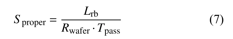
where Sproperis the proper motor speed; Lrbis the length of right baffle; Tpassis time for the first brain section to pass through the entire right baffle; Rwaferis the radius of the silicon wafer. At the second stage, as the sectioning continues,the motor speed should be adjusted based on the real time microscopic detection results.

Fig.9. Illustration of the coordinate representation of detection results.
Finally, the control algorithm for the motor speed can be summarized in Algorithm 1 whose key steps are explained as follows.
1) In the first phase, the initial motor rotation speed is determined by (7).
2) At the beginning of collection, if there is an un-collected section (section in the set of NSCC) passing the lower edge of the right baffle, then set the motor rotation speed to the estimated rotation speed in the first phase.
3) During the collection process, if all the un-collected sections never pass the lower edge of the right wafer and there is no section in the collection area (no section in the set of BCSS), the rotation speed is set to be zero to wait for the uncollected section to move to the collection area. This can help to increase the total number of collection sections on single silicon wafer.
4) At the end of collection, if there are more than two sections appearing on the left side of the left baffle, then it means that the wafer is full and the rotation speed is set to zero to stop this collection cycle.
Remark 2: It is noted that there are very few automatic brain section collection devices in the literature. One representative device is the ATUM invented by Hayworth et al. [18].Although this device has many applications involving array tomography [19]–[21], the collection manner of ATUM actually belongs to the open-loop control mode, i.e., the collection rate of the ATUM is set with respect to the knife's slicing rate and cannot be adjusted according to the real collection state. This fact means that the uncertainty tolerance ability of the ATUM is low. In addition, because the tape substrate used by the ATUM has a low conductivity, the tape substrate has to be bonded to a silicon wafer with conductive adhesive and coated with conductive film to increase the imaging quality, which requires complicated follow-up operations and skilled operators.

C. Graphical User Interface of the ASUM
In order to facilitate the operation of the ASUM, a simple graphical user interface (GUI) is designed. The GUI of ASUM integrates the open-loop collection system and the automatic collection system. As shown in Fig.10, the left area in the GUI is used for displaying the microscopic video which is acquired from the microscope CCD camera. In the open-loop collection mode, the operator can easily adjust the motor rotation speed by adjusting the slider button in the “Open-Loop Control Mode” column such that the ASUM can be adjusted to the appropriate working state. At the same time,the actual rotation speed of the silicon wafer can be displayed in the “Working State” column. In addition, the operator can easily adjust the ASUM to the closed-loop collection mode by opening the switch in the “ Closed-Loop Control Mode”column. The graphical user interface of ASUM is developed on Linux platform by using PyQT toolkit.

Fig.10. Initial graphical user interface of the ASUM.
IV. EXPERIMENTS
In order to verify the ASUM’s collection ability, the experimental results of the open-loop collection are presented.First, the experimental results of microscopic object detection are presented, and the closed-loop collection results based on the proposed automatic collection system are also presented.Finally, in order to verify the advantages of the silicon-based collection method adopted by the ASUM in subsequent electron microscopic imaging, the experimental comparison of the silicon-based collection method and the tape-based collection method in electron microscopic imaging is presented.
A. Open-Loop Collection Results
In order to verify the effectiveness of the designed ASUM,the open-loop collection experiment of brain sections has been conducted with the help of operators. As shown in Figs. 11(a)and 11(b), the ASUM can automatically collect the brain sections from the knife boat after the preparation process. The operator needs to set the appropriate motor rotation speed according to the size of the brain tissue sample and the slicing speed of the ultra-microtome. They also need to control the start and stop of the rotary motor at the beginning and the end of the collection process, respectively.
Although the designed ASUM device can collect brain sections in the open-loop collection mode in an orderly fashion, there may be a sparse arrangement of collected brain sections on the silicon wafer. As shown in Fig.11(c), in the process of collecting brain sections, the brain sections at the end of the baffle may appear to be adsorbed by the silicon wafer at a faster speed, while the brain sections between two baffles have not been pushed onto the silicon wafer. As mentioned in Section II, this is due to the water surface unevenness between the silicon wafer and the baffles of knife boat, and the strong adsorption of the silicon wafer on brain sections. Therefore, even if the slicing speed of the ultramicrotome is constant, the advancement speed of brain sections at the end of the baffle may change. In this case, the brain sections collected by the silicon wafer rotating at a constant speed are not evenly arranged, which leads to a waste of collecting space. In open-loop collection mode, to properly solve this issue, the operator is required to adjust the wafer’s rotation speed by the observation of microscopy.
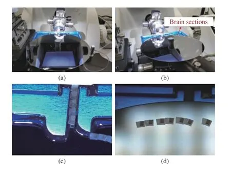
Fig.11. Illustration of the open-loop collection of brain sections based on the ASUM: (a) Local map of the AUSM before brain section preparation;(b) Local map of the ASUM in the collection process; (c) Section collection process in the microscopic view; (d) The collected brain sections in the microscopic view.
B. Microscopic Object Detection
In order to train the microscopic object detection model, a microscopic image set of brain sections (ASUM-3) is prepared. To build the ASUM-3 data set, a rat brain hippocampal tissue sample block is sliced into brain sections by the ultra-micorome and knife boat with baffles, and the ASUM is used to collect the brain sections. During the preparation and collection of brain sections, several microscopic videos of brain sections are captured by the CCD camera. From these microscopic videos, 1416 images with 1280 × 1024 are sampled for the data set preparation. The LableImg annotation tool is used to annotate three kinds of objects among the collected images: brain sections, left baffle and right baffle. In the ASUM-3 data set, 708 images are used for model training and validation, and 708 images are used for model testing.
The SSD detection model used in this experiment is based on the Pytorch deep learning software framework. The network optimization process uses a stochastic gradient descent algorithm (SGD) with a momentum of 0.9, where the weight decay term is set to be 0.0005. The initial learning rate is set to be 0.001, and a total of 12 000 small batch iterations(batch size is 32) are performed during the training process.The learning rate of the last 4000 iterations is set to 0.0001. In order to speed up the convergence of the model and alleviate the issue of limited samples in the training data set, the basic network needs to be pre-trained on the ILSVRC CLS-LOC data set, and the auxiliary network formed by the extra feature layers is initialized by the Xavier initialization method.
The detection results on the ASUM-3 data set are shown in Fig.12. It can be seen that the trained SSD detection model could effectively detect the brain sections, left baffle, and right baffle in the microscopic images. By using the mean average precision (mAP) required by the VOC challenge [47],the trained SSD model achieves 96.96% mAP in testing.

Fig.12. Detection results by the SSD detection algorithm on the ASUM-3 data set: (a) The detection results before preparation of brain sections; (b) The detection results in the preparation of brain sections.
Remark 3: This paper adopts the “SGD+Momentum”method to optimize the network because this method has a rapid convergence rate and can reduce the possibility of trapping at the local minimum points. To illustrate the advantage of the “SGD+Momentum” optimization method compared to other optimization methods such as the “Adam”method, the following comparison experiment has been conducted on the public benchmark dataset (VOC2007/2012)and the brain section dataset ASUM-3. From Table I, it can be found that in both cases, the “SGD+Momentum” optimization method outperforms the “Adam” optimization method.

TABLE I PERFORMANCE COMPARISON OF THE “SGD+MOMENTUM”OPTIMIZATION METHOD AND THE “ADAM”OPTIMIZATION METHOD
C. Closed-Loop Collection Results
In order to verify the designed automatic control system of ASUM based on the microscopic object detection, the closedloop collection experiment based on the proposed automatic control strategy is carried out. Through the graphical user interface, the ASUM can be easily adjusted to the automatic collection mode by pressing the button in “Closed-Loop Control Mode” column. It can be seen that the silicon wafer can be automatically set to the appropriate speed without manually setting the motor speed, and the operator does not need to intervene the entire collection process.
To illustrate the effectiveness of the proposed automatic control strategy for the ASUM, comparison experiments have been conducted. First, the proposed automatic control algorithm based on microscopic detection is used in the ASUM. The estimated speed of the electric rotating machinery is 0.32 r/min and the motor speed is adjusted based on real time microscopic detection results in the section’s collection process. The collection result is shown in Fig.13(b). The collected brain sections (138 sections in total)arranged in a circle on the silicon wafer in an orderly fashion.Second, the collection process is conducted without using the proposed automatic control strategy, i.e., the motor speed is constant during the collection process, and the rotation speed is set to be 0.32 r/min for a fair comparison. The result of the open-loop collection is shown in Fig.13(a). It can be seen that the collected brain sections (89 sections in total) are arranged more sparsely on the silicon wafer. In this comparison experiment, the automatic collection strategy based on the microscopic object detection has increased the number of brain sections collected onto a single silicon wafer by 55%.Using the proposed microscopic detection method and the control strategy, the ASUM can achieve an efficient collection of brain sections without additional manual intervention.
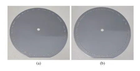
Fig.13. Comparison of the open-loop collection and the closed-loop collection of brain sections: (a) The collection result (89 sections in total) in the open-loop collection mode; (b) The collection result (138 sections in total)in the closed-loop collection mode.
D. Electron Microscopic Imaging Results
In order to verify the electron microscopic imaging quality of brain sections collected by the proposed ASUM, the comparison experiment based on silicon substrates and the tape substrates is carried out. As mentioned in Section I, the ATUM is currently widely used in array tomography, which uses the tape substrate to collect brain sections. However, due to the poor conductivity of the tape substrate, the charge accumulation effect is easily generated in the subsequent electron microscope imaging process, which affects the quality of electron microscope imaging. The tape with collected brain sections needs to be cut into small segments and bonded to the silicon wafer by conductive glue.Considering the non-conductivity of the tape substrate, it is necessary to coat a conductive film on the tapes with a high vacuum coating instrument (Leica-EM ACE 600, Germany),which can increase the surface conductivity to alleviate the effect of charge accumulation in the imaging process. With the proposed ASUM, the brain sections are collected on the silicon substrates, and the silicon wafer with collected brain sections can be directly sent into the imaging chamber of scanning electron microscope (ZEISS SUPRA55, Germany)for imaging, without the tedious post-processing steps.
The comparison experimental results of imaging quality between the silicon substrate and the tape substrate have been shown in Fig.14 . According to experimental results, the distortion of collected brain sections is not obvious, which is similar to the one conducted by the operator’s manual collection. This distortion can be compensated by the imaging processing algorithm in the follow-up three-dimensional reconstruction process. The brain sections collected on the silicon wafer results in satisfactory imaging quality electron microscope imaging. After the operation of conductive film coating, the brain sections collected on the tape substrate can also result in good image quality with the electron microscope, however, there is still a relatively small difference compared to the brain sections directly collected on the silicon substrate. From Figs. 14(a)–14(f), the contours of mitochondria and vesicles of brain sections collected by ASUM are more clear compared to the images of brain sections collected by ATUM, and different parts of brain tissues are obviously viewed. In addition, from Figs. 14(g) and 14(h), the contours of blood vessels and cell bodies of brain sections collected by ASUM are more clear as well. It is known that the clear contour information is more beneficial for the three-dimensional reconstruction of the nervous system. This observation can demonstrate that the ASUM using the silicon wafer as the substrate can not only avoid the tedious operation but also achieve a satisfactory electron microscope imaging quality.
V. LIMITATION DISCUSSION
The goal of this paper is to design a device for automatic collecting brain sections. In the literature, the most popular method is with ATUM which adopts a tape-based collection manner. However, this collection manner requires some extra conductivity-enhancement operations for the tape substrate.This gave the motivation of designing the ASUM in this paper. However, ASUM has its own limitations as well. The ATUM can collect thousands of brain section one time.However, the ASUM can only collect 100 sections per wafer.To increase the throughput of ASUM, wafer replacement should be considered, which requires a manual operation in the current setting. Therefore, with respect to throughput, the ASUM cannot reach the level of ATUM. In addition, the replacement of silicon wafers is required to stop the ultramicrotome. This may cause a depth change of the first section in the next collection cycle, which may reduce the imaging quality. It should also be noted that the current ASUM is still a lab prototype. Although the ASUM can always collect the brain sections onto the silicon wafer, the number of collected brain sections is relatively small. In the future, with the increase of the manufacturing precision and the advancement of the perception and control methods, the throughput of ASUM is expected to be significantly improved.
VI. CONCLUSIONS AND FUTURE WORK

Fig.14. Imaging quality comparisons through the electron microscope: (a),(c), (e), (g) The imaging results based on ASUM (the silicon substrate); (b),(d), (f), (h) The imaging results based on ATUM (the tape substrate).
Array tomography is a fundamental technology of brain science research, and its application requires the highefficiency and high-quality collection of serial brain sections.In this paper, an automated silicon-substrate ultra-microtome(ASUM) is proposed for automatically collecting brain sections. The ASUM collects brain sections directly onto the silicon substrates, which ensures the quality of electron microscopic imaging of brain sections without cumbersome post-processing operations. The ASUM is designed in a selfcontained structure to accommodate different types of ultramicrotome. To partially liberate the operator in the collection process, an automatic collection system is designed for the ASUM. In the automatic collection system, the SSD detection method is used to detect three kinds of foreground objects in the vision of microscope: the brain sections, left baffle and right baffle. Based on the microscopic object detection results,an automatic control strategy is proposed to adjust the working state of the ASUM. At the same time, considering the convenient operation of the ASUM, a concise graphical user interface is designed. To verify the effectiveness of the proposed ASUM and the corresponding automatic collection system, experiments involving open-loop and closed-loop collections are carried out, respectively. Experimental results show that the ASUM in the closed-loop collection mode can not only realize the automatic collection of brain sections, but also increase the number of brain sections collected on one single silicon wafer compared to the open-loop collection. The comparison experiments in electron microscopic imaging show the advantages of the ASUM in the imaging process. In the future, the object detection method for low quality microscopic images is a future topic to be studied (i.e.,microscopic images are corrupted by noises or include incomplete information). It has been reported that nonnegative latent factor models have certain strengthens for these kinds of images [48]–[51]. Some efforts will be made by combining the proposed detection methods and the nonnegative latent factor models to improve image quality and increase the detection accuracy. In addition, the automatic replacement of silicon wafers to increase the throughput of ASUM is to be investigated.
杂志排行
IEEE/CAA Journal of Automatica Sinica的其它文章
- Physical Safety and Cyber Security Analysis of Multi-Agent Systems:A Survey of Recent Advances
- Joint Algorithm of Message Fragmentation and No-Wait Scheduling for Time-Sensitive Networks
- Multiagent Reinforcement Learning:Rollout and Policy Iteration
- A Survey on Smart Agriculture: Development Modes, Technologies, and Security and Privacy Challenges
- A Survey of Evolutionary Algorithms for Multi-Objective Optimization Problems With Irregular Pareto Fronts
- Dependent Randomization in Parallel Binary Decision Fusion