Signal Acquisition and Processing Method for Capacitive Electromagnetic Flowmeter
2021-04-02
Abstract—A kind of signal acquisition circuit and the related signal processing method of the capacitance electromagnetic flowmeter (EMF) were introduced.The circuit can eliminate the influence of distributed capacitance on the input impedance of the operational amplifier,and greatly improve the input impedance of the detection circuit to overcome the disadvantage of high signal source impedance.The rotating capacitor filter is a signal processing method based on the phase-sensitive detection technology.It can extract the weak signal from the strong and wideband background noise,so it is very suitable for the processing of capacitive electromagnetic flow signals.Through the comparison of the signal amplitude obtained at different flow rates and the comparison of signal spectrum components before and after the filter,the effectiveness of the bootstrap signal acquisition circuit and rotating capacitor filtering method is verified.
1.Introduction
The electromagnetic flowmeter (EMF) is a kind of instrument based on Faraday's law of electromagnetic induction to measure the flow rate by picking up the induction voltage when fluid flows through the magnetic field[1],[2].As one of the most commonly used flowmeters in various industrial applications,EMF usually is with high precision and causes no pressure loss[3],[4].For its high precision and absence of no moving part,EMF appears extensively advantages in the water system,as well as food,pharmaceutical,and other process industries.
Traditional EMF uses a metal electrode that penetrates the measured tube wall to obtain the induction signal.When measuring viscous substances,the electrode is easy to be polluted,which affects the measurement results.Capacitive EMF uses the capacitance coupling method to obtain the induction signal,the detection electrode pastes on the outer side of the measuring tube wall and does not contact the measured fluid,which effectively solves the problem of being polluted and can realize the long-term maintenance-free operation.
At present,related research mainly focuses on the compensation of the velocity profile and electromagnetic flow tomography.Multiple electrodes and excitation coils are placed on the outside wall of the measuring tube to accurately identify the velocity distribution of the fluid across the cross section of the pipe[5],[6].The related technology can be applied to the situations including open channels,multiphase flow,and weakly conductive liquid measurement[7]-[9].
2.Capacitive Type EMF
According to Faraday's electromagnetic induction principle,when a conductor cuts the magnetic line of force in the magnetic field,the induced voltage will be generated at both ends of the conductor.The liquid flowing in the tube can be regarded as a conductor,so when it flows and cuts the magnetic lines that pass through the measured tube,the voltage that reflects the flow rate will be generated.In an ideal case,the magnitude of voltage is linearly proportional to the velocity,so the flow rate can be calculated from the induced signal picked up by electrodes through the capacitance coupling way.The structure of the sensor part of the capacitive electromagnetic flowmeter is shown in Fig.1.
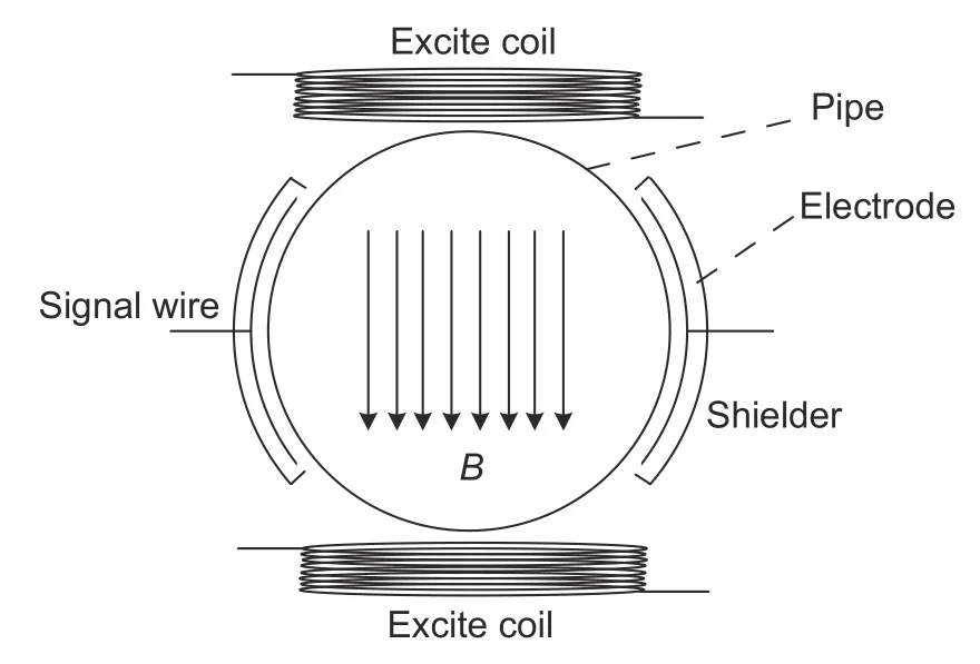
Fig.1.Sensor structure of the noncontact EMF.
The magnetic field vertically applied on the pipe is generated by two excitation coils which are connected in serial at the opposite side of the pipe wall and driven by the excitation signal.The induced voltage is distributed in the direction perpendicular to both the magnetic field and velocity.The magnitude is proportional to the change rate of the magnetic flux that passes through the detection circuit,which means that it is related to the velocity of the liquid,the strength of the magnetic field,and the diameter of the pipeline.Ideally the induced voltage can be expressed as
whereUis the induced voltage,kis the proportional coefficient,φis the magnetic flux,Bis the magnetic field strength,Lis the length of the conductor cutting the magnetic field,andVis the average flow velocity of the liquid.
In general,the magnetic field and flow profile in the measuring tube are non-uniform.So the structure and size of the sensor need to be carefully considered during the design,and methods should have been used to make the distribution of the magnetic field as uniform as possible to make the relationship between induced voltageUand flow velocityVas simple as possible[10]-[12].
Two detection electrodes are placed on the tube wall perpendicular to the direction of the magnetic field and flow velocity to pick up the induction signal.The coupling capacitance is constructed by the measured liquid,measuring tube wall,and detecting electrode.The measured liquid and the detecting electrode act as the two plates of the capacitor,and the measuring tube wall acts as the dielectric.The measuring tube is generally made of polyvinyl chloride (PVC) or industrial ceramics,and the coupling capacitance varies from several picofarads (pF) to dozens of pF according to the area of the electrode and the thickness of the tube wall[13]-[15].
It can be seen from the way of signal acquisition that the induced signal must be in an alternating current (AC)form,otherwise,it will be isolated by the coupling capacitance and cannot be detected.Therefore,the sine wave is used as an excitation signal at the beginning and changed to the single-frequency square wave and doublefrequency square wave,which are commonly used at present.The sine wave method can avoid the electrode polarization,but there are in-phase and differential noise in the circuit,which have the same frequency with the excitation signal and need to be eliminated by the careful design.The square wave excitation mode uses the square wave with positive and negative polarities as the excitation signal,which can greatly reduce the in-phase interference and electrode polarization phenomenon.There is large differential noise at the moment,when the excite signal switches its polarity,so the voltage acquisition should be carried out when the signal tends to be stable,which can greatly improve the accuracy and stability of EMF.Since the signal obtained from the electrodes of capacitive EMF is very weak and often mixed in the noise with a large amplitude,how to extract a weak useful signal from the strong noise becomes the key problem to be solved in the design of EMF.
3.Preamplifier Circuit Design
3.1.Signal Characteristic Analysis
To ensure the quality of the collected induction signal,there are two difficulties that need to be considered:Weak induction signal and high source impedance.The signal amplitude can be raised by increasing the turns of the excitation coil and the driving current,which increase the magnetic field strength applied on the measuring tube.But the increases of coil turns and wire diameter lead to a large volume of excitation coil,which is not suitable for the space constrained situation.
As the signal strength is hard to be improved significantly,a feasible method is to avoid the loss of the signal in the process of signal acquisition.The source impedance of the induction signal,which is determined by the capacitance and the frequency of the excitation signal,is the key factor that affects the quality of signal acquisition.The lower source impedance is good for signal acquisition,which can be obtained by increasing the source capacitance and using the higher excitation frequency.The common ways to increase the coupling capacitance include increasing the area of the detection electrode,using the tube made of high dielectric constant material,and reducing the thickness of the tube wall.It was shown in [14]that when a 3-mm thick ceramic tube wall and the 36.0 mm × 19.2 mm metal film electrodes were used,the capacitance between one electrode and the liquid was about 1 pF to 2 pF.Although the methods mentioned above can increase the capacitance,there are some disadvantages at the same time,for example,the larger electrode will pick up more eddy noise and the thinner pipe wall will reduce the strength which cannot be used in a high-pressure transmission situation.
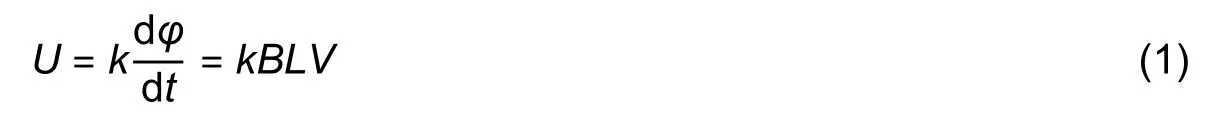
It is theoretically true that the higher excitation frequency will make the induction signal easier to pass through the coupling capacitance and pick up by signal acquisition circuit,but the high-frequency excitation will make the differential noise increase significantly.Nakataniet al.studied the relationship between the excitation frequency and flow noise[16],and the result is shown as Fig.2.
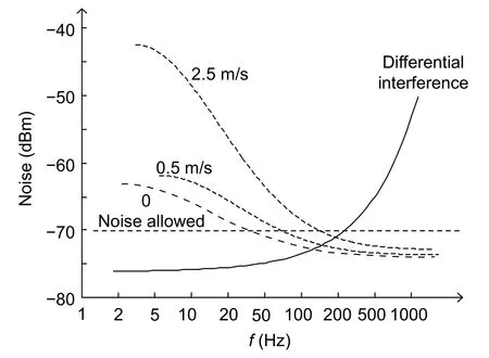
Fig.2.Relationship between frequency and noise.
The dashed line is the flow noise and the solid line is the differential interference.It can be seen from Fig.2 that when the excitation frequency is about 200 Hz,both the differential noise and flow noise have a small amplitude at the same time,which makes it suitable for the excitation frequency of capacitive EMF.When the sensor capacitance is in the pF level and the excitation frequency is 200 Hz,the impedance of the signal source is about 1 × 10⁹Ω,which places higher requirements on subsequent preamplifier circuits.
3.2.Bootstrap Amplifier Circuit
The bootstrap circuit is a kind of preamplifier circuit that is widely used for its high input impedance.The diagram of the bootstrap circuit is shown as Fig.3.In Fig.3,Ciis the equivalent capacitance of the sensor andC1is the bootstrap capacitance.The operational amplifier(op-amp) is connected as a voltage follower,so the outputVo(t) equals to the input signal at point A.Through the feedback capacitorC1,the upside potential of resistorR2is raised (bootstrap),so that both ends of resistorR1are equipotential.If op-amp is regarded as ideal,the input impedance is infinite,the current of the input loop is zero,and the impedance of the preamplifier circuit is infinite.
Fig.3.Structure of bootstrap circuit.
In practice,the bias current at the input of op-amp and the path through the distributed capacitance to the ground makes the input impedance decrease.Because the values of the electrode and distributed capacitance are very close,the influence of the distributed capacitance on the input impedance cannot be ignored.
In order to counteract the decrease of the input impedance caused by the bias current of op-amp and the leakage current of the distributed capacitor,a feedback capacitor is added to compensate the leakage current.The practical bootstrap circuit with the feedback compensation is shown as Fig.4.
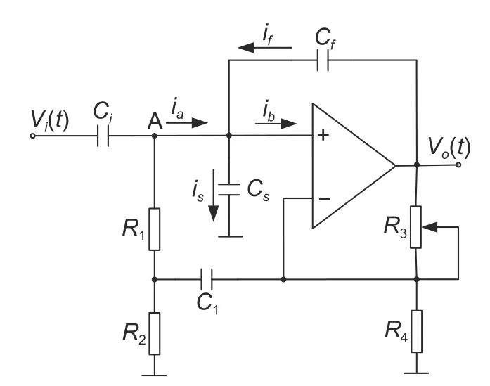
Fig.4.Structure of bootstrap circuit.
In Fig.4,Csis the equivalent input capacitor of op-amp and connected to the ground,Cfis the feedback capacitor,andibis the bias current of op-amp.ResistorsR3andR4are used to set the gain of the circuit that can be expressed as (1+R3/R4) >1,which ensures the compensation current flows from the output to the input point A.When the currentifequals to the sum ofisandibby adjustingR3,the currentiaequals zero.This method can reduce the requirements for op-amps and the input impedance of 1×10¹²Ω or more can be easily achieved,which ensures the accuracy of the measurement.SinceCfis a positive feedback capacitor,the circuit will oscillate if it is overcompensated.Therefore,R3must be carefully adjusted to keep the circuit work at the condition of under-compensation[17].
4.Rotating Capacitor Filter
4.1.Principle of Rotating Capacitor Filter
Since the voltage collected by the electrode is very weak and contains strong noise,how to extract the useful signal from strong interference is another important problem.According to the characteristic that the induced signal has the same frequency as the excitation source,the lock-in amplifier can be used for EMF to extract flow rate signals submerged in the background noise.
There are two ways to build the lock-in amplifier:Analog and digital.Digital lock-in amplifiers use microprocessors to replace core components,such as filtering and phase-sensitive detection of analog lock-in amplifiers.The analog input signal is converted to the digital type by the analog/digital (A/D) converter and then sent to the processor for digital signal processing.The reference signal is generated by the processor and can be flexibly adjusted to adapt to changes in the input signal,so better results can be obtained[18]-[20].However,digital lock-in amplification requires a large amount of data calculation work,and it is a heavy burden to the embedded processors with low computing power.Therefore,the analog lock-in amplifier circuit is still widely used for its simple structure and excellent filtering performance.
As a special form of the lock-in amplifier,the rotating capacitor filter can realize the functions of filtering and phase-sensitive detection and has been widely used in scientific research and industrial applications for the ability of noise suppression and amplifies signals with a specific frequency.The theory diagram of the rotating capacitor filter is shown as Fig.5.
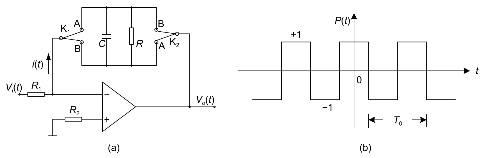
Fig.5.Principle of rotating capacitor filter:(a) circuit structure of rotating filter and (b) control pulse waveform.
Fig.5 (a) shows the structure of a rotating capacitor filter constructed by op-amp.K1and K2are the electronic double-pole-double-throw (DPDT) switches controlled by the pulse signalP(t) shown in Fig.5 (b),which is a square wave with the frequencyf0that can be imported from outside or generated inside the system.WhenP(t) is high,DPDT switches to the terminal A simultaneously;whenP(t) is low,DPDT changes to the terminal B.Thus the current sourcei(t) periodically changes the direction that is controlled by the electronic switch to charge the RC circuit,which is equivalent to multiplyi(t) by +1 and -1.
4.2.Performance Analysis of Rotating Capacitor Filter
The current source modulated by the electronic switch can be expressed as

If the period ofP(t) isT0and the angular frequency isω0=2π/T0,the Fourier expansion ofP(t) is
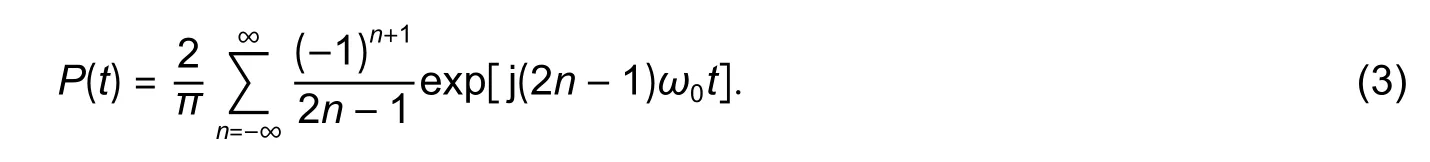
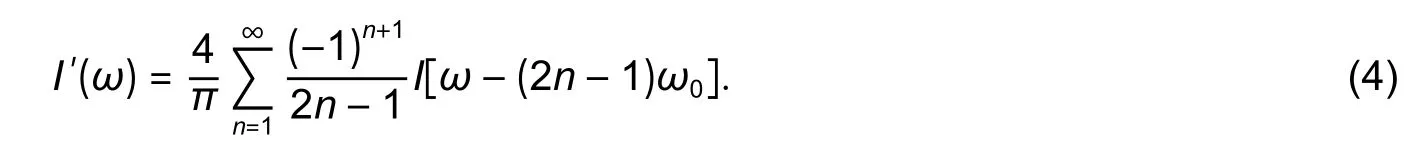
Take (3) into (2) and use the Fourier transformation,i′(t) can be expressed in the frequency domain as
后来,单位的主管安排好我的座位后,我才发现坐在我前面的这个背影很熟悉。“你好,我叫沙莉。以后我们还要多多合作。”她转过身,朝我微笑着说。
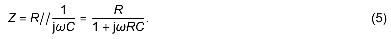
For the signals with the angular frequencyω,the impedance of the RC parallel circuit is
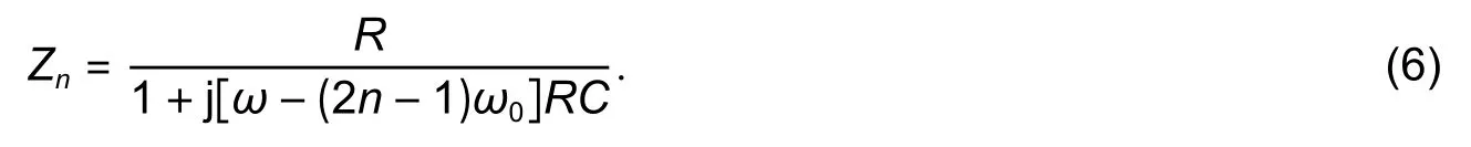
Due to the modulation ofP(t),the currenti′(t) that passes throughZis composed of different frequency components.For each component,the complex impedance of the RC parallel circuit is different.For a componentI[ω−(2n−1)ω0],the complex impedance of the RC parallel circuit can be expressed as
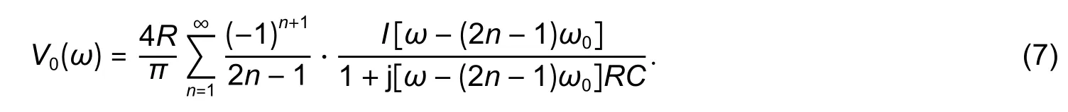
Therefore,the spectra of the output voltageVo(t) can be regarded as the product ofI′(ω) withZn,which can be expressed as
Because ofVi(t)=−R1i(t),the transfer function can be expressed as
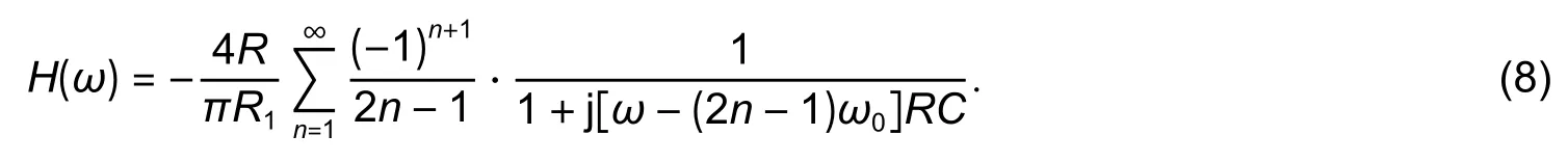
It can be seen from (8) that the rotating capacitor filter is equivalent to a comb filter with the center frequency of(2n−1)f0,wheren=1,2,and 3,as shown in Fig.6.
It performs narrow-band filtering on the component of the input signal with the frequencyf0and its odd harmonics,while suppressing the noise at other frequencies.Its output is an approximate square wave with a frequency off0and the amplitude is proportional to the input signal.The larger theRC,the narrower the frequency band,and the stronger the ability of suppressing noise[21].Through rectifying and low-pass filtering,a direct current (DC) signal that is linearly related to the flow rate can be generated.
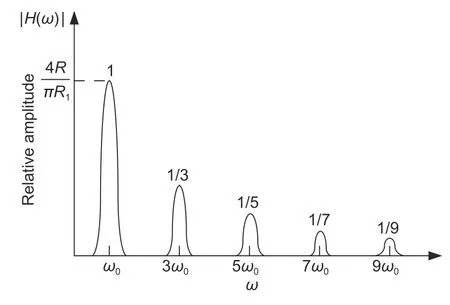
Fig.6.Amplitude frequency response of rotating capacitor filter.
5.Experiment Results
5.1.Experimental Device Configuration
The block diagram of the signal acquisition and processing circuit is shown in Fig.7.
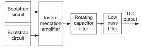
Fig.7.Constitution of the signal acquisition and processing circuit.
The bootstrap amplifier circuit acts as a preamplifier to pick up signals from two electrodes and followed by an instrument amplifier.The signals are differentially amplified to eliminate the common mode interference and sent to a rotating capacitor filter to remove the remaining noise.The output of the signal processing circuit is a DC voltage that is linearly related to the flow rate after the rectifier circuit.The switch signal of the rotating capacitor filter is obtained directly from the excitation signal to achieve the synchronization.
5.2.Experiment Results Analysis
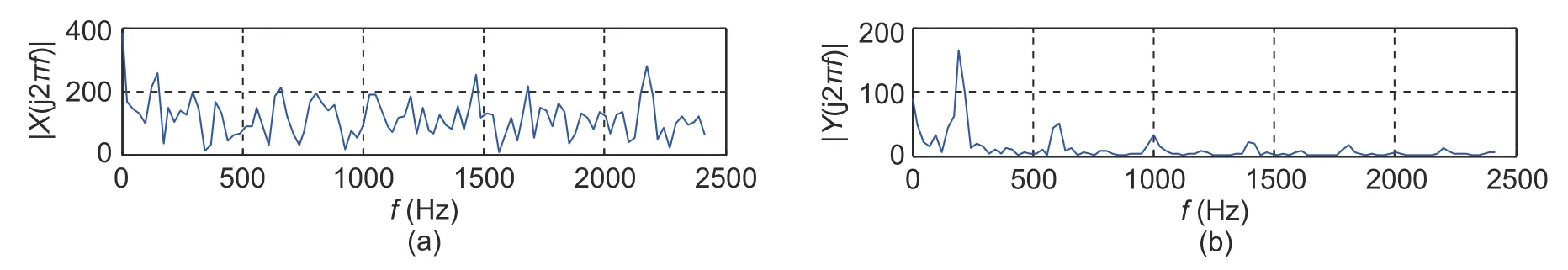
Fig.8.Spectrum of induction signal before and after filtering:(a) spectrum of input signal of filter and (b) spectrum of output signal of filter.
It can be known from the previous analysis that the induced voltage has the same frequency as the excitation signal,so it should be located at the same point at the horizontal axis of the spectrum diagram,that is,at 200 Hz.However,it can be seen from the upper spectrum diagram in Fig.8 that the input signal is mixed with more noise components,and its spectrum extends from the low-frequency to the high-frequency region,and all maintain a high amplitude.At certain frequency points,the amplitude of the noise is much larger than that of the wanted signal.So the raw signal from the output of the amplifier circuit must be processed properly before it can be used to obtain the true flow rate information.
From the diagram in the lower part of Fig.8,it can be seen that the frequency spectrum of the signal processed by the rotating capacitor filter is nearly the same as the frequency spectrum of the comb filter shown in Fig.6.The filtered signal has relatively large peaks only at the fundamental frequency of the excitation signal and its odd harmonic frequencies.The maximum occurs at the fundamental frequency,where true flow information is being reflected.This shows that the rotating capacitor filter can effectively filter out the noise other than the useful component in the flow induction signal,and the performance of the rotating capacitor filter constructed by the discrete electronic components is fully in line with expectations which can significantly improve the signal-to-noise ratio.
The waveform shown in Fig.9 is obtained from the output of the rotating capacitor filter,when the fluid remains at the still state and keeps flowing in the measuring tube.The left figure is about the static state and the right one is for the flowing state.
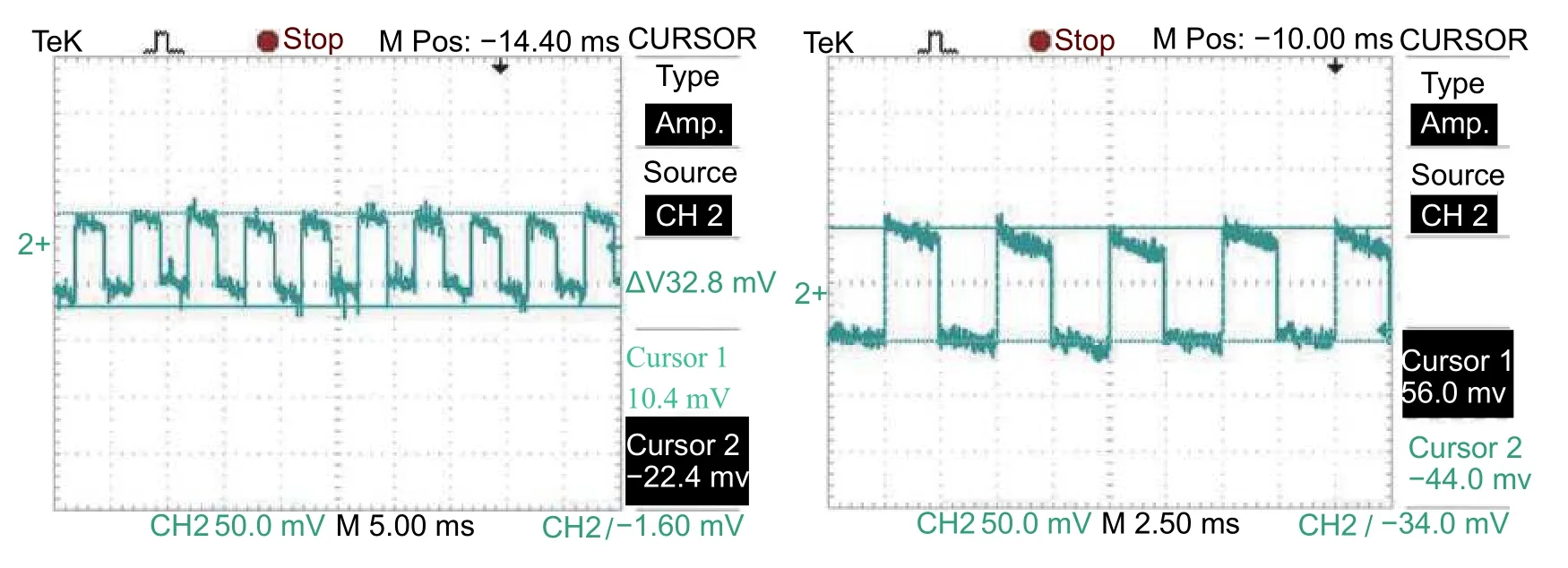
Fig.9.Waveform of filtered signal at different flow rates.
It is well known that the signal picked up by the electrodes is very weak,usually at the microvolt (μV) level,but it can be seen from Fig.9 that the output of the filter is already at the millivolt (mV) level after being amplified by the amplifier circuit.When the fluid flows up,the induced voltage increased,which caused the amplitude of the square wave changes accordingly.Traditional amplifier circuits only have the ability to amplify signals,so both noise and useful signals are amplified at the same time,which cannot improve the signal-to-noise ratio.The rotating capacitor filter has both frequency selection and amplification functions,it can amplify useful signals while suppressing the noise,which greatly improves the quality of the signal.The gain of the filter can be simply set by resistorR1in Fig.5 (a),and it does not affect the noise bandwidth of the circuit.
Although the rotating capacitor filter can extract weak signals from the strong interference noise,its performance is also limited in some cases.For example,when the frequency of the noise is the same with the useful signal,the rotating capacitor filter will not work properly.This can be observed in Fig.9,when the fluid is stationary,the filter still outputs a square wave with a small amount of noise superimposed on it.
There are two reasons for this phenomenon:1) Even if the fluid is stationary,there are in-phase and quadrature noise in the circuit,which are caused by the alternating magnetic field.The frequency is the same as the excitation frequency,so the rotating capacitor filter cannot effectively filter it out and will output it as an effective flow signal.2) The noise spectrum is wide and the passband of the comb filter centered on odd harmonic frequencies of the excite signal is not narrow enough.In this case,some of the noise falls into the sidebands of the comb filter.The rotating capacitor filter will not be able to distinguish it with the actual flow signal and causes the system to generate an incorrect response which eventually results in the zero drift of the flowmeter.
Therefore,in order to minimize the effects of the noise,special measures and extra care need to be taken to eliminate them from useful signals.For the first case,the following measures should be adopted,such as reliable shielding of detection electrodes,transmission wires,and signal acquisition circuits,so that the signal wires are completely parallel with the magnetic field line to keep the magnetic flux through the circuit loop as low as possible.Because in-phase and quadrature noise is only related to the excitation frequency and the change rate of the magnetic flux in the circuit loop,it remains fixed after the sensor design is completed.So they can be seen as systematic errors and eliminated by calibration.For the second case,methods should be used to minimize the width of the passband.A related study by [21]shows that the total equivalent noise bandwidth of a rotating capacitor filter is
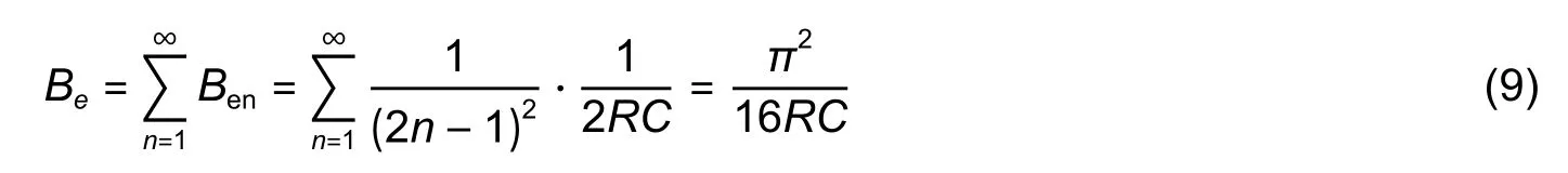
whereBeis the total equivalent noise bandwidth andBenis the width of the passband of the odd frequency.It can be seen from (9) that the passband width of the noise can be reduced by increasing the value ofRC,a narrower passband allows less noise to pass through so that the zero point of the flowmeter will be stabilized.
In order to further improve the performance of the flowmeter,based on the fact that the induced voltage should be a single-frequency signal and the noise is evenly distributed throughout the frequency range,a bandpass filter can be added between the amplifier circuit and the rotating capacitor filter to preprocess the signal,most of the noise will be filtered out,and the performance of the rotating filter is maximized.
6.Conclusion
How to extract the weak magnetic induction signal from strong interference noise is one of the difficulties in the realization of capacitive EMF.The bootstrap circuit can be used as the preamplifier to effectively overcome the adverse effect of the extremely high impedance of the source and ensure the quality of the acquired signal.Since the signal detection circuit of EMF works in the environment that contains complex and strong electromagnetic interference,the acquired signals are inevitably mixed with various types of noise,although shielding methods are used.According to the characteristics of the wide noise frequency distribution,the frequency-selective filtering characteristics of the rotating capacitor filter are used to extract the induction signal with the same frequency as the excitation signal to obtain a more ideal flow signal.The analysis of experimental data also proves the effectiveness of the above method.
Disclosures
The authors declare no conflicts of interest.
杂志排行

Journal of Electronic Science and Technology的其它文章
- Annotation of miRNAs in the COVlD-19 Novel Coronavirus
- Molecules against COVlD-19: An in Silico Approach for Drug Development
- lmpact of Coronavirus Pandemic Crisis on Technologies and Cloud Computing Applications
- Identification of the Potential Function of circRNA in Hypertrophic Cardiomyopathy Based on Mutual RNA-RNA and RNA-RBP Relationships Shown by Microarray Data
- Bioinformatics Analysis on lncRNA and mRNA Expression Profiles for Novel Biological Features of Valvular Heart Disease with Atrial Fibrillation
- lmage Classification with Superpixels and Feature Fusion Method