The theoretical study on intermittency and propagation of geodesic acoustic mode in L-mode discharge near tokamak edge
2021-03-22ZhaoyangLIU刘朝阳YangzhongZHANG章扬忠SwadeshMitterMAHAJANAdiLIU刘阿娣TaoXIE谢涛ChuZHOU周楚TaoLAN兰涛JinlinXIE谢锦林HongLI李弘GeZHUANG庄革andWandongLIU刘万东
Zhaoyang LIU (刘朝阳), Yangzhong ZHANG (章扬忠),Swadesh Mitter MAHAJAN, Adi LIU (刘阿娣), Tao XIE (谢涛),Chu ZHOU (周楚), Tao LAN (兰涛), Jinlin XIE (谢锦林), Hong LI (李弘),Ge ZHUANG (庄革) and Wandong LIU (刘万东)
1 School of Nuclear Science and Technology, University of Science and Technology of China, Hefei 230026, People’s Republic of China
2 Center for Magnetic Fusion Theory,Chinese Academy of Sciences,Hefei 230026,People’s Republic of China
3 Institute for Fusion Studies, University of Texas at Austin, Austin, TX 78712, United States of America
4 School of Science,Sichuan University of Science and Engineering,Zigong 643000,People’s Republic of China
Abstract Through a systematically developed theory, we demonstrate that the motion of Instanton identified in Zhang et al(2017 Phys.Plasmas 24 122304)is highly correlated to the intermittent excitation and propagation of geodesic acoustic mode (GAM) that is observed in tokamaks.While many numerical simulations have observed the phenomena, it is the first theory that reveals the physical mechanism behind GAM intermittent excitation and propagation.The preceding work is based on the micro-turbulence associated with toroidal ion temperature gradient mode,and slab-based phenomenological model of zonal flow.When full toroidal effect is introduced into the system, two branches of zonal flow emerge: the torus-modified low frequency zonal flow (TLFZF), and GAM, necessitating a unified exploration of GAM and TLFZF.Indeed, we observe that the transition from the Caviton to Instanton is triggered by a rapid zero-crossing of radial group velocity of drift wave and is found to be strongly correlated with the GAM onset.Many features peculiar to intermittent GAMs, observed in real machines,are thus identified in the numerical experiment.The results will be displayed in figures and in a movie; first for single central rational surface, and then with coupled multiple central rational surfaces.The periodic bursting first shown disappears as being replaced by irregular one, more similar to the intermittent characteristics observed in GAM experiments.
Keywords: zonal flow, drift wave, intermittency, GAM, L-H mode
1.Introduction
In this paper, we construct a possible theoretical-computational pathway for the intermittent excitation of geodesic acoustic mode (GAM), observed, routinely, on several tokamaks such as ASDEX [1], T-10 [2], JFT-2M [3, 4], HL-2A[5,6],DIII-D[7],JET[8,9],EAST[10].Experimentally,the GAM is an intermittent, random, discrete temporal structure.More specifically, the GAM in the frequency range of 10-20 kHz does not last long; typically, it lasts a few milliseconds(e.g.0.5-5 ms)before disappearance,and then reappears in a shorter period of time.The entire cycle-the intermittency period-is less than 1 ms near the plasma edge [5, 6] and longer than 1 ms away from the plasma edge [1, 2, 10].During its occurrence, the GAM amplitude varies with no recognizable (so far) pattern.

Figure 1.2D mode structure of toroidal ITG used in this paper,calculated according to the theory of[11]and the parameters of this paper,whereρ ≡r a,/ r is the radial position,a is the minor radius,ϑ is the poloidal angle.
We begin with presenting a theoretical framework for extending the framework of[11]-the zonal flow-drift wave system [11]-to include GAM (the relevance of ion temperature gradient (ITG) to GAM excitation in low mode discharge near tokamak edge has been discussed in appendix A).‘Extending’simply means that much of the content developed in [11] will be reused in this paper, i.e.the knowledge of toroidal ITG mode in two scales.In meso-scale, it is the ITG wave envelope equation modulated by zonal flow.In microscale, it is the toroidal ITG eigenmode.The 2D linear mode structure pertaining to a single central rational surface is shown in figure 1.The mode structure is required for calculating Reynolds stress and group velocity in zonal flow equation and ITG wave envelope equation respectively.
Two toroidal features of the ITG mode are clearly seen from figure 1: (1) the mode is ballooned towards bad curvature side; and (2) the radial scale is much broader than the poloidal one, implying quite a few sidebands are coupled to the central rational surface.
While the framework of ITG can be reused,however,the zonal flow equation in reference [11] should be greatly modified.Toroidicity has two effects on the zonal flow equation.On one hand,it augments the screening factor from slab Hasegawa-Wakatani model [12-15], depending on the collisionality; on the other hand, it causes coupling to sinusoidal sound wave through geodesic curvature.A free parameteraneois phenomenologically introduced in reference[11]to address the first issue.In order to resolve the second issue,one ought to derive the zonal flow equation in tokamak configuration, which is precisely one task of this paper.In summary, we will reuse all microscopic scale related formalism, including linear toroidal ITG eigenmode equations,ballooning solutions for both eigenvalue and 2D mode structure, the derived Reynolds stress and group velocity in[11].It is also important to mention that the wave envelope equation(9)and its eikonal solution equation(13)in[11]will be reused in this work as equation(20);what will be different from[11]is the zonal flow equation(equation(14)),the model in meso-scale, which should be modified to incorporate toroidicity.To this purpose two basic moment equations (charge and particle conservation) for the axisymmetric mode (a synonym of zero toroidal number mode) are derived in appendix B.Based on these two equations the toroidal zonal flow equation set is derived in section 2.It consists of two coupled equations,the zonal flow()equation(equation(18)),now it is coupled to the first harmonic sinusoidal component of sound wave due to geodesic curvature, and equation (19) for sound wave ().These two equations can be merged into one single equation in terms of zonal flow () as shown in appendix D, where the explicit coupling form of the two branches TLFZF (withaneo:= 1 +2q2,q is the safety factor of tokamak) and GAM is clearly seen.The basic form of the paper,i.e.the three coupled equations(equations(18)-(20)),is fully described in section 2.In addition, the physics of transition from Caviton into Instanton5Caviton and Instanton are two distinct phases in the evolution of drift wave envelope in the presence of zonal flow.They do not refer to quasi-particle.Caviton refers to a long-lived standing wave phase, and Instanton refers to a short-lived traveling wave phase (in radial direction).The transition from Caviton to Instanton occurs as soon as radial group velocity crosses zero.When Instanton leaves reaction region Caviton emerges in the reaction region gradually.The process can be seen in the movie ‘GAM spatiotemporal evolution’associated with figure 6.The following four terms defined in[11]may cause confusion and will be replaced in this paper and hence forth.(1)‘a pair of caviton’ is replaced by ‘Caviton’.(2) ‘instantons’ is replaced by‘Instanton’.The uppercase suggests that they are special term, not ordinary English word.(3)‘decay’is replaced by transition(noun)or transit(verb).(4)‘drift wave energy’ is replaced by ‘drift wave envelope’.and the role played by radial group velocity crossing zero are explained briefly at the end of section 2.
The set of three equations (18)-(20) represents a wellposed initial value problem under specific boundary conditions as shown in section 3.The numerical methods,though essentially the same as in[11],are described in detail so that this paper is self-contained.In section 4, figures and one movie are displayed to discuss leading characteristics of GAM generated by ITG for single central rational surface.The GAM onset looks like periodic bursting.In section 5 the coupling between multiple central rational surfaces is investigated with arbitrarily chosen initial phase.The inclusion of coupling makes the periodic bursting disappear,and the resulting response looks more like the intermittent excitation observed in tokamaks.The physics regarding GAM propagation is studied systematically in section 6; its pattern is highly correlated with motion of Instanton and dependent on the sign of weak dispersive media.In section 7, summary and discussion of our findings are presented.In appendix A, we critically examine what may be the most likely source of micro-turbulence generating zonal flows-GAM phenomenon.Data on GAM experiments from nine discharges on 7 machines were collected and analyzed.Because of high collisionality, the well-known collisionless trapped electron mode (TEM or simply CTEM), and the dissipative trapped electron mode are excluded, from consideration.We also provide a few examples of experimental data showing that GAM could occur in ITG unstable region.Appendix B is devoted to a derivation of the charge and particle conservation equations for axisymmetric electrostatic mode; these equations constitute the basics for understanding the close relationship between TLFZF and GAM.A somewhat technical calculation for poloidal moments of Reynolds stress is given in appendix C.In appendix D,it is shown that,for the low frequency branch,TLFZF is consistent with equation(14)of [11], where the free parameter is determined to beaneo:= 1 +2q2;for the high frequency branch,it is consistent with the GAM dispersion in Fourier representation of [16].
2.The zonal flow equation set in tokamak
In the existing literature,the LFZF equation and equation for GAM are derived separately.However, we will soon show(based on the Braginskii two-fluid equations[17])that these equations are simply two branches of a unified zonal flow system.We will assume the geometry of concentric circular magnetic surfaces in a toroidal coordinate system.Such a simplified framework should be sufficient for the exploration of the qualitative features of GAM intermittency.The starting point of the investigation is the set of two coupled conservation equations for the axisymmetric electrostatic mode [18], derived in appendix B.
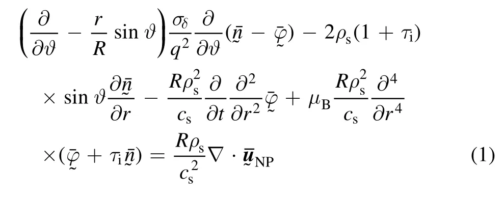
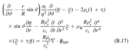
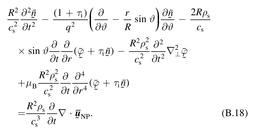
In the toroidal coordinate system(r,ϑ,ς) ,wherer,ϑ,ςare respectively the radial, poloidal and toroidal coordinates,the charge conservation and particle conservation equations are (see equations (B.17), (B.18)):
and

Due to the large parallel conductivity (e.g.σδ>102) in tokamak plasmas, the leading term in equation (1) is

For this study,it is natural to splitandinto two parts:the zonal density-flow partno poloidal dependence) and the partthat depends on the poloidal angle [18]:

Equation (3), containing onlyϑderivatives, will requirethe leading order response is, thus, adiabatic.
Averaging over the magnetic surface [18] (ε≡the inverse aspect ratio)

on equation (1) yields

The magnetic surface average of equation (2) yields
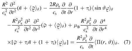

Table 1.Characteristic functions and values of equation (10).

Equation(8)implies that the zonal density arises from the first cosinoidal component ofhowever, at the order of O(ε).
Equation(8)is now used to eliminatenfrom equation(2)to yield
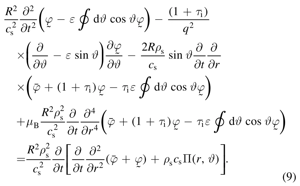

Since equation(10)does not contain radial derivative∂∂r,/φcan be separated as

Interestingly, if we further split theϑdependence asexpthe homogeneous part of equation(10)can be cast into the canonical Mathieu equation[19]

Substituting these characteristic functions into equation (9) yields
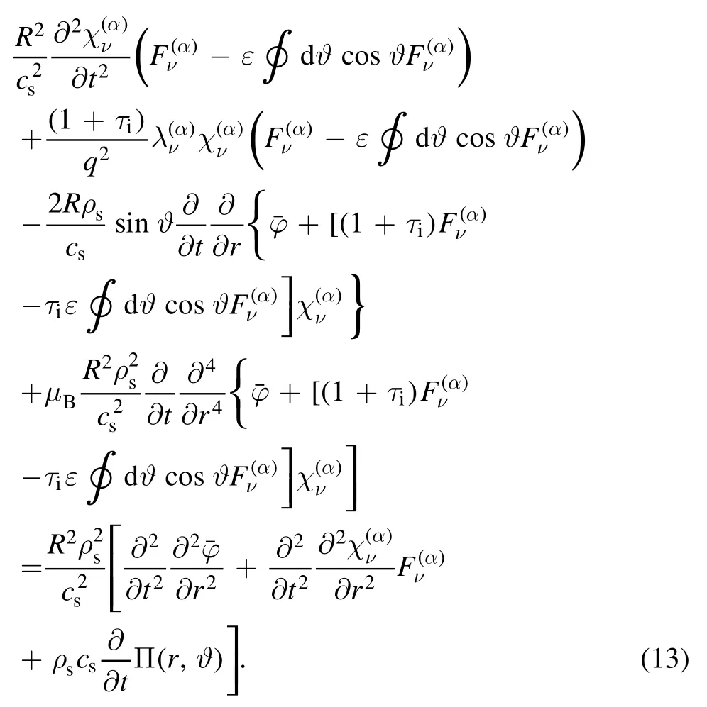
Because the Mathieu characteristic functions constitute an orthogonal complete set, multiplying equation (13) byand integrating overϑyields the radial equation of each harmonic.For the first sinusoidal component,ν= 1 andα=s:, the radial equation becomes


In equation (15) the last term is

the average micro-turbulence drive that generates the zonal flow and GAM; the quantity behind the second order radial derivative in equation(16)is the well-known Reynolds stress.
The poloidal moment of the Reynolds stress (introduced by the toroidal coupling)is obtained upon performing surface average on equation (14)

In equation (17)K(ϑ)=1,sinϑ,cosϑ,sin 2ϑ.The analytical expression forcan be obtained straightforwardly as shown in appendix C.
Equations (14) and (15) constitute the zonal flow-sound wave system purely based on Braginskii fluid model.The equivalent zonal flow equation pertaining to the single rational surface, equation (15) becomes


As mentioned in the introduction that equation (13) in [11] will be reused, it is simply quoted here6A minus sign is missing in equation (13) of [8].

Bμabeing the measure of anomaly.In equation (20)is the poloidal wave vector, andnis for toroidal mode number of ITG mode.At the mode rational surface, the poloidal mode numberbeing the safety factor.
A crucial comment, regarding the weak dispersivefinite Larmor radius (FLR)-termin equation (19), is in order.In our results from Braginskii model, the dispersive coefficientτDe( ) is proportional toHowever, GAM propagation observed in experiments [20, 21] seems to suggestVarious results of positiveτDe( ) have been obtained by making use of gyrokinetic theories, however, most of them do not have valid cold ion limit [16].According to the derivation of[16] by Smolyakov et al,D(τe) is a function ofτe.For warm ions it is positive and becomes negative in cold ion limit, the same as what we obtained.The abovementioned discrepancies in existing literature can be seen,e.g.in figure 3 of[23]for the comparison of[16]with[24,25](for gyrokinetic derivation).There are two groups working on basis of fluid model in literature, with FLR correction [26] and without FLR correction [27,28].The FLR correction makes negative dispersive coefficient increase with growing ion temperature to positive as shown in figure 4 of[26].Qualitatively it is very similar toτDe( ) in [16].Without FLR correctionτDe( )remains negative.In this paper,we just simply take the result of [16] and/or [26] as if the FLR term in the fluid model moves from cold ion to warm ion.The related GAM propagation issue will be discussed in section 6.
Equations(18)and(19)are two components of the zonal flow equation set in tokamak.This is in contrast to[11]where only one component exists.The second component comes into the system because of the toroidal coupling to sinusoidal component of sound wave owing to the geodesic curvature.The two component set contains two branches in different frequency regime GAM and TLFZF.Interested readers may wonder if the low frequency branch of this set is consistent with the discussion in [11].The answer to this question is‘yes’ as briefly discussed in appendix D.
Before carrying out numerical calculations, it may be appropriate to briefly describe the physics involving transition of Caviton into Instanton,and the role played by radial group velocity etc (for details, please see section V of [11]).
As shown in equation(20),the zonal flow modulates drift wave envelope in phase(~cos Θ,whereφis the envelope of the drift wave).The radial group velocityυ rg appears as the argument ofυunder integral, describing the movement of drift wave envelope along the radial characteristic lineAccording to the calculation of drift wave group velocity (ITG fluid model in [11] and in this paper),υ rg always consists of two consecutive distinct phases:a long slowly varying part (at high level) and a short sudden spike crossing zero.Notice that the zonal flowυ(in this paragraph refers to LFZF only)is localized around the region where the Reynolds stress is not small (reaction region).Before crossing zero,υ rg is large,rgwould run out of the reaction region depending on the reference positionr, whereυis too small to contribute to the integral in equation (20).This process corresponds to formation of Caviton asΘ is slowly varying.Uponυ rg zero-crossing, the sign is changed,makingrgsmaller, and pulling the local integrandυback to the reaction region, makingυcontribute toΘ again.Such a process occurs on different instants at different reference positions, just like wave propagation.It annihilates Caviton into Instanton and propagates along withrg,takingΘ far away from reaction region.The details can be seen from figures 6-10 in [11], in particular figure 7.
In fact,based on equation(20)it is straightforward to show that right afterυ rg crosses zero Instanton is the linear traveling wavewheretgis the zero crossing time,and
3.Numerical methods for the dimensionless zonal flow equation set
We first list the various normalization introduced in[11].The zonal flow speed is normalized totime is normalized tothe dimensionless micro-radius is defined asis the magnetic shear,stands for the turbulence level at the dimensionless peak position of static Reynold stressThe zonal flow Reynolds number is defined asand the dimensionless Reynolds stress isThen we define the dimensionless first harmonic sinusoidal component of sound wave to beBy introducing two frequencies


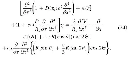
The solution of the initial value problem is worked out for the initial conditions:andSince the phase modulation of drift wave envelope is significant only inside the so-called reaction region, where the Reynolds stress is not small, the boundary condition for drift wave envelope is not important;the latter is relevant only in the Instanton phase that has a vanishing coupling to zonal flow outside reaction region.However, the signal of phase functionΘ could propagate to a place far away from the reaction region denoted by±∞x,where the cutoff has been introduced
The boundary condition for the zonal flow equation set has to be set up differently with respect to left and right sides in contrast to [11], since the data of GAM are measured not too far away from plasma edge, and edge effects on GAM could be important.On the right side, the zero Dirichlet(reflecting) boundary condition is chosen at the plasma edge forwherexedgedenotes the position of plasma edge ( =r a).On the left side, an absorptive boundary condition is set up [31].It sits far away behind turning points.
The dimensionless set of equations (22)-(24), combined with the assumed boundary conditions, constitutes a wellposed initial value problem,which is solved by making use of the finite difference methods, where the spatiotemporal grids are discretized asand =mM0, 1,..., are integers.In this paper we choose=K512,=M12 000,where=ℓstands for the peak position of static Reynold stress(the region from−rj,2torj,2is more or less the reaction region) andstands for the half width of the Gaussian peak (the analytic formulae of static Reynold stress are given in equations (C.26)−(C.28)).The dimensionless spatiotemporal step sizes areandrespectively.
The zonal flow equation set (equations (22), (24)) is solved by making use of the 2nd order Crank-Nicolson method [32] with accuracy up to 6×10⁻³forThe wave envelope equation (equation (23)) is directly integrated as shown in appendix C of [11].

Table 2.Basic equilibrium parameters.

Table 3.Partial mode related parameters.
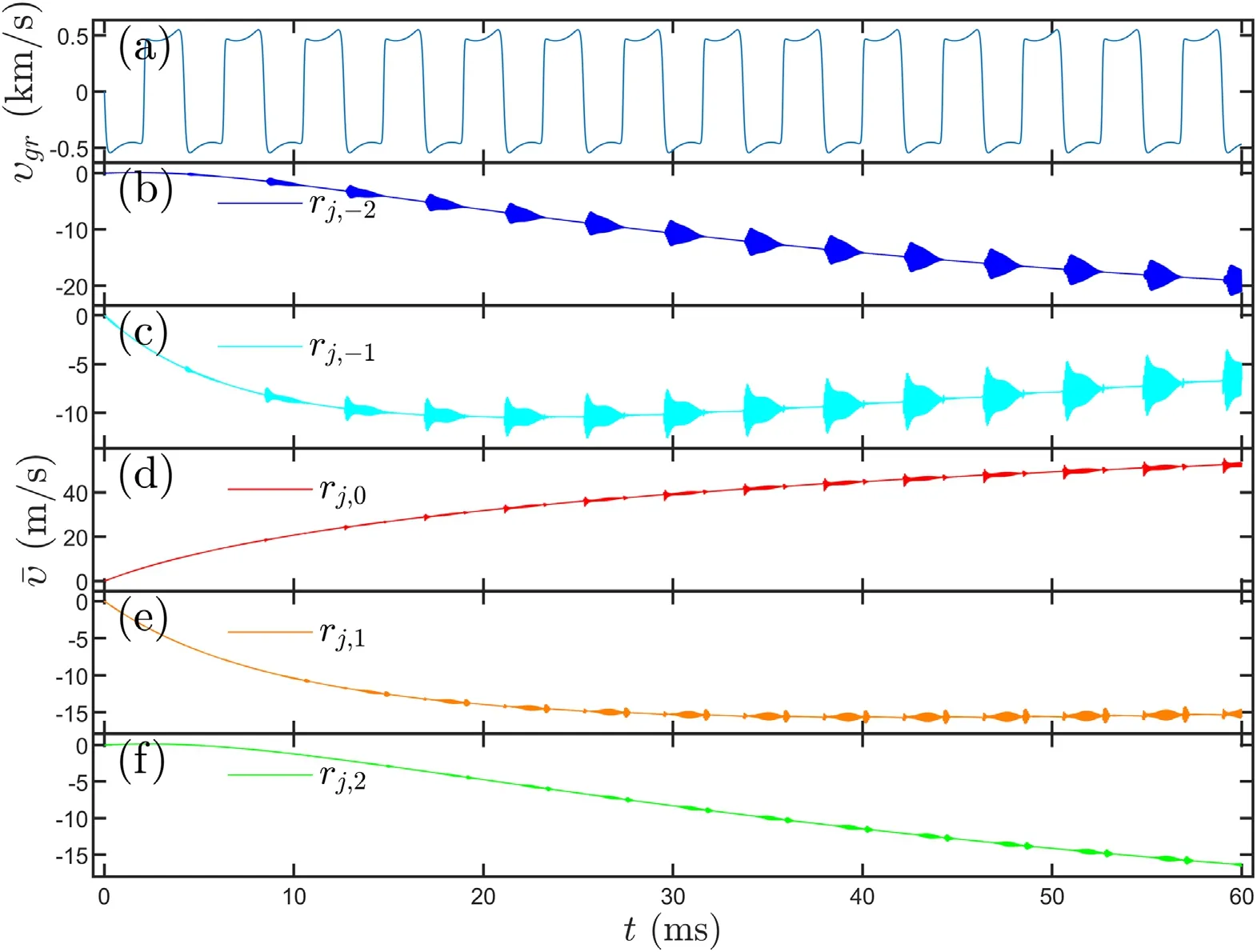
Figure 2.(a)Temporal evolution of radial group velocity and(b)-(f)zonal flow with intermittent excitation of GAM at five radial positions,(b) r j, −2 ,(c) r j, −1, (d)r j,0 ,(e)r j,1, (f)r j,2.
For illustrative purposes the numerical experiment is performed for the parameters corresponding to the shot#141958 on DIII-D [7] shown in table 2 (whereis the density(ion temperature)gradient length,B,NeandTeare the equilibrium magnetic field, electron density and temperature at the position of rational surfacerjrespectively).
Some ITG related parameters required for Reynolds stress are listed in table 3(where the parametersη,2β1andβ2are related to ITG mode structure [11],σandx0are related to Reynolds stress structure and defined in appendix A,ωin this table stands for the real frequency of ITG mode).
4.The periodic bursting of GAM for single central rational surface
In this section ITG is assumed to be the micro-turbulence generating zonal flow as suggested by appendix A.The numerical results are presented for single central rational surface only.The more realistic case with coupling between multiple central rational surfaces is presented in the next section.

Figure 3.The magnified graphs in one period (54-60 ms) of figure 1 with low frequency portion filtered out.

Table 4.Five radial points near the peak position of static Reynold stressrj,0 and the radial position of ±∞x .
The periodic bursting of GAM can be clearly seen in figures 2 and 3 at five distinct radial positions (defined in table 4, in which the radial positions of±∞xare also given).One can also see that the periodic bursting of GAM is highly correlated with the downward as well as upward zero-crossing of radial group velocity,and the typical period~4 ms,is within the experimentally observed range, e.g.2-5 ms in ASDEX-U [1], 2-4 ms in T-10 [2], 1-3 ms in HL-2A [5, 6].The structure of temporal evolution is spatially-dependent,this is also consistent with experimental observations in the sense that no temporal pattern is recognized so far.One can also observe that the GAM amplitudes increase with higher level of TLFZF from figure 2, since zonal flows as a whole are driven by inhomogeneous Reynolds stress term, as seen from equation (D1).The downward (upward) zero-crossing results in stronger (weaker) and longer (shorter)-lasting GAM.The similar patterns shown in figure 3 are also reported in JFT-2M (figure 2(d) of [4]), JET (figure 7 of [9]), and EAST (figure 8 of [10]).
The frequency-time spectrogram, like that shown in figure 4(a), has been reported in ASDEX-U (figure 13(a) of[1]) and in T-10 (figure 20 of [2]) with similar bursting characteristics.It is also reported in HL-2A (figure 19 of [5]and figure 3(a)of[6]),however, with quite different bursting periods.Noticeably,the measurement in HL-2A is done very close to the plasma edge.
The temporal evolution of spatial structure for the zonal flowυand its high frequency componentυGAMis presented in figures 4(b) and (c) respectively.Similar spatiotemporal patterns, however, have not yet been reported in experimentsperhaps because of its fine radial structure, and inadequate spatial resolution of diagnostics.Right after 54.7 ms, the socalled pre-GAM (around GAM frequency, but irregular spatial structure) is generated moving inwardly as driven by the ingoing Instanton (see corresponding wave envelope pattern in the movie in the caption of figure 6(Multimedia view),and also in snapshots in figures 6(a)-(c)).When the wave front hits the turning points, only a portion is reflected back outwardly.The coherent pattern is thus formed and evolves into a semi-eigenmode till ~56.83 ms when the Caviton transits into outgoing Instanton.A shorter life-time pre-GAM is generated, but it gradually dissipates away.The reflection boundary at plasma edge has little effect on the subsequent behavior because the incoming wave near plasma edge is not strong enough to support a reflected wave that could reach the turning point to yield what could be classed as a full eigenmode [22].
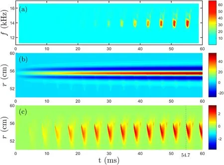
Figure 4.(a) Frequency-time spectrogram at rj,0, (b) and (c) for spatiotemporal evolution for the zonal flowυ and its high frequency componentυGAM respectively.

Figure 5.Auto-correlation function for different radial positions at(a) rj, −1 and (b)r j,0.
The quantitative study of GAM randomness has been documented in [7] by making use of auto-correlation function.The auto-correlation function defined by equation (B.2)in appendix B of[7]is a very useful concept in experiment.It could reveal the nature of the observed intermittency, i.e.whether essentially stochastic or deterministic.The measurement is displayed in figures 15(a) and (b) of [7] for two different radial positions, also reported in figure 9 of [10].Similar ‘numerical measurements’ are carried out and presented in figure 5 for two spatial positions.While the patterns are somewhat different from those in experiments,they share one very important feature, a long tail after non-exponential quick fall-off.The non-exponential quick fall-off is inconsistent withf1/ scaling[1];the long tail indicates long lasting dynamics in the system.
It is very important to note that the experimental data used for autocorrelation are filtered near GAM frequency.The temporal evolution of the perpendicular velocity is also reported using filtered data in figure 8 of [10].Both the reported figures are very similar to figure 5 presented here.
In addition to figure 4(c),the spatiotemporal evolution of GAM can,equivalently,be represented by the movie−‘GAM spatiotemporal evolution’ in the caption of figure 6 (Multimedia view).It captures not only the clear radial structure of GAM as a snapshot at any time, but also the temporal correlation to the motion of drift wave envelope.Since the movie can only be viewed online, nine distinct snapshots are selected and displayed in figure 6.Two physical quantities,the high frequency zonal flowυGAMand the normalized wave envelope represented by Θcos ,2are displayed jointly on the same time base during a cycle;the temporal(spatial)range is 54-60 ms (48-60 cm).This choice of spatial dimension is reasonable because:(1)the plasma edge is at 60 cm,set to be the right boundary, i.e.the reflection boundary for outgoing zonal flow; (2) the so-called turning point lies within 52-55 cm as seen from figure 4(c),also from close-up figure 10(b)ρwithin 0.87-0.92;the latter serves to be the reflection layer for the ingoing pre-GAM.Let us see how the entire dynamics unfolds.
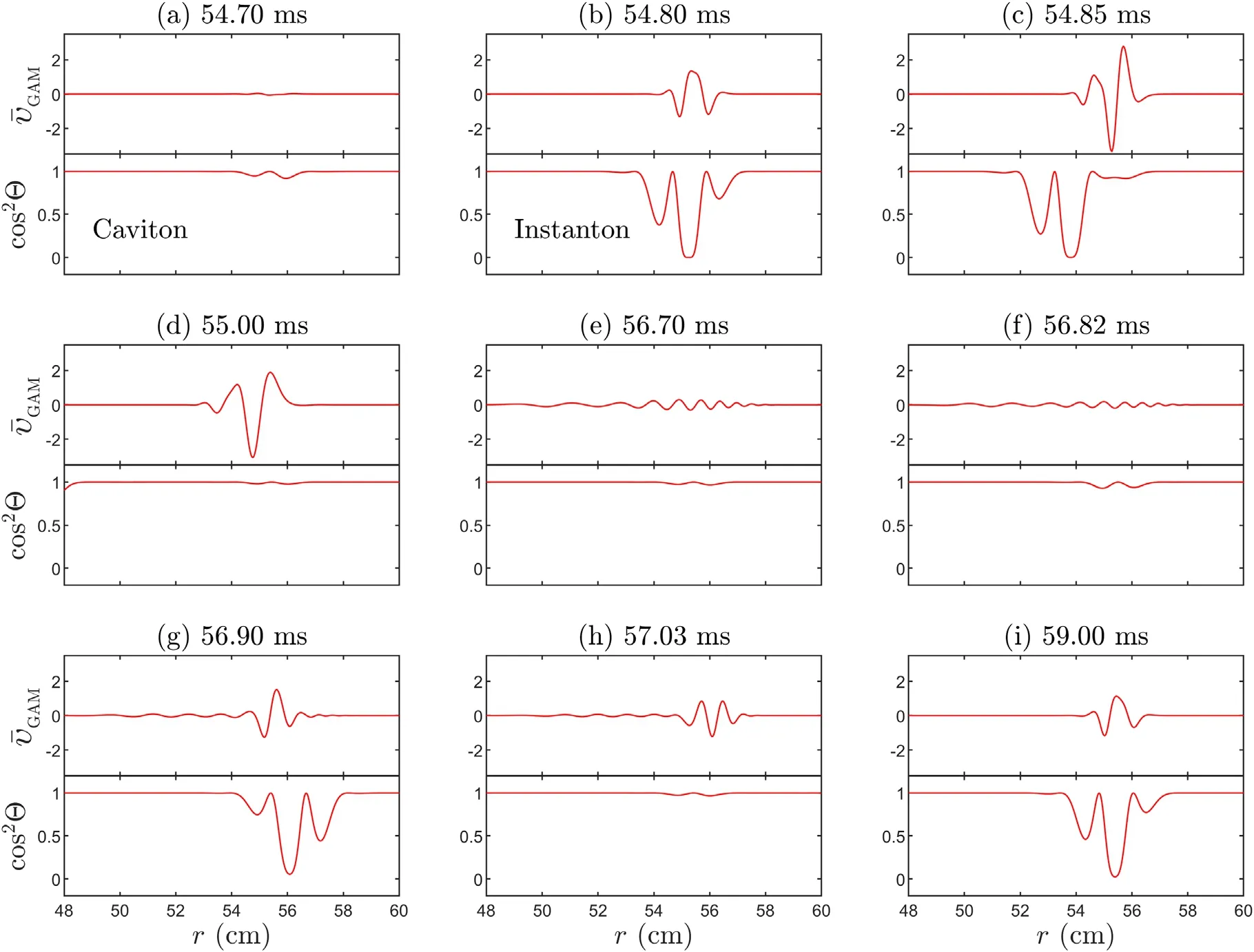
Figure 6.Snapshots of 9 time points in the movie, (a) 54.70 ms, (b) 54.80 ms, (c) 54.85 ms, (d) 55.00 ms, (e) 56.70 ms, (f) 56.82 ms, (g)56.90 ms,(h)57.03 ms,(i)59.00 ms.The time evolution for 54-60 ms can be seen via the link(http://home.ustc.edu.cn/~lzy0928/GAM%20spatiotemporal%20evolution.mp4) ‘GAM spatiotemporal evolution’ (Multimedia view).
Initially, between 54 and 54.7 ms, a slowly breathing Caviton emerges, and begins to grow (figure 6(a)).During a very short period of time 0.1 ms(from 54.7 to 54.8 ms)three events occur, almost simultaneously: (1) the amplitude of normalized wave envelope grows-crosses half and eventually becomes unity, (2) the pre-GAM starts to form rapidly in the reaction region (where static Reynolds stress is not small), and (3) the Caviton transits into Instanton(figure 6(b)).Right after 54.85 ms Instanton quickly propagates inwards and brings up the ingoing pre-GAM(figure 6(c)).The ingoing Instanton disappears after 55 ms and a new Caviton starts to form and breathe slowly in the reaction region (figure 6(d)).At this moment, the pre-GAM front reaches the turning point; the penetrated part is then absorbed somewhere further inward, while the reflected part moves outwards.After that, the interference between the ingoing and outgoing zonal flow around GAM frequency results in the transit phase of forming an ‘eigenmode’between the turning point and the right edge of reaction region.At 56.7 ms (figure 6(e)), the outgoing GAM reaches the right zero boundary (GAM cannot propagate outside the last closed magnetic surface), and then is reflected back to form semi-eigenmode between plasma edge and the turning point till 56.82 ms (figure 6(f)).At this moment a Caviton starts first to grow and then transits into outgoing Instanton.Right after 56.9 ms, the Instanton quickly propagates outwards (figure 6(g)) inducing right moving pre-GAM overlapped with the existing outgoing GAM.Such an interference results in a rather complicated pattern till 57.03 ms(figure 6(h)), at that moment the outgoing Instanton runs outside the reaction region.Afterwards, the GAM gradually dissipated away.The process mentioned above occurs almost repetitively at 59 ms when another Caviton grows and transits into ingoing Instanton (figure 6(i)).A new instance of pre-GAM is generated and moves inwardly just at that moment.
5.GAM in the coupling between multiple central rational surfaces
In previous sections the physics of GAM associated with a single rational surface is discussed.This is surely an idealized situation since coupling with nearby rational surfaces is bound to affect the GAM characteristics.It is particularly true in our case, since the width of reaction region pertaining to one central rational surface covers at least 11 neighboring central rational surfaces(within a range of 1 cm).Because the phase between the neighboring rational surfaces is not definitive, the coupling would inevitably bring complexity into the full system, which is likely to be different from shot to shot, i.e.irreproducibility will be automatic.
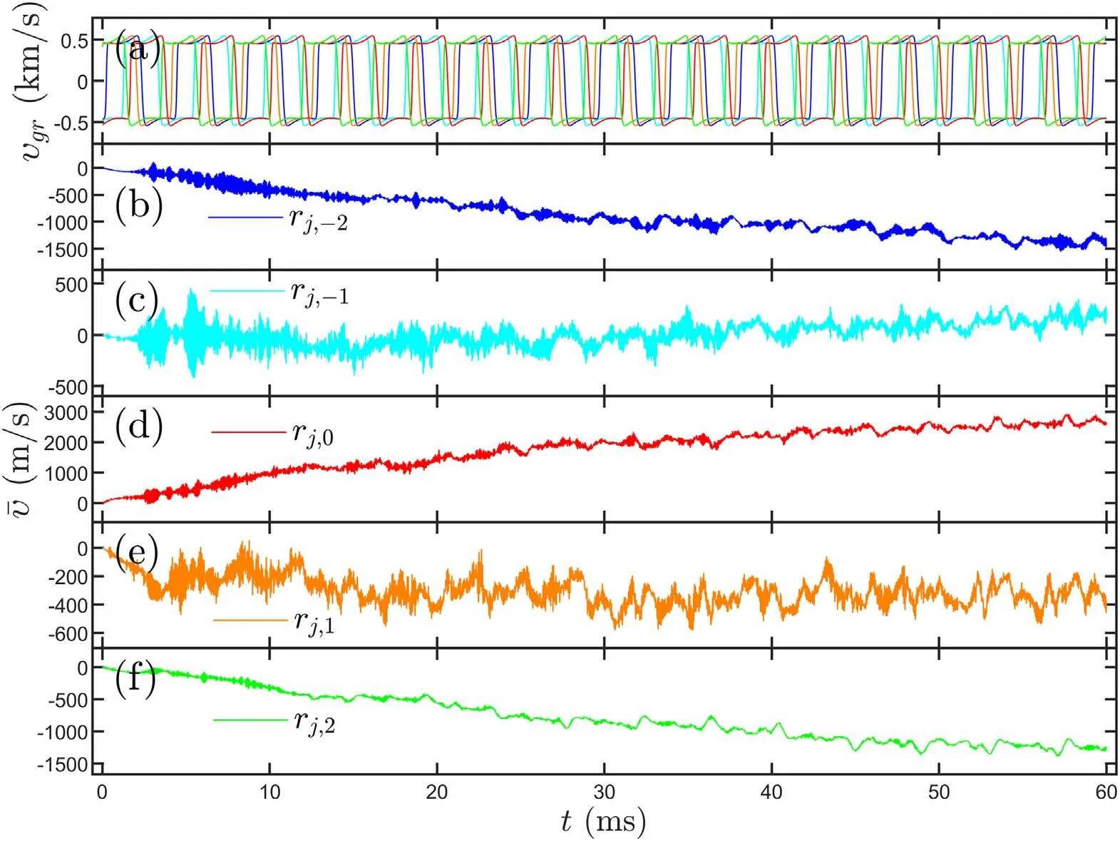
Figure 7.(a)Temporal evolution of radial group velocity of five rational surfaces: j= −4(blue),j=−2(cyan), j =0(red), j =2(crown),j =4(green),(b)-(f)zonal flow in the coupling between 11 rational surfaces at five radial positions,(b) r j, −2, (c) r j, −1, (d)r j,0, (e)r j,1, (f)r j,2.
The zonal flow equation, in which coupling among 11 rational surfaces (jmax=5) is included, comes out to be

whereγFdenotes the flow damping rate and is set to be a constant frequency (10 Hz).The phase function associated with each rational surface,influenced by the same zonal flow,is

whereϑjis the integral constant of the poloidal characteristic line,It is reasonable to assume thatϑjis an arbitrary number inπ[0, 2 ] such that for each rational surface the zero crossing time of radial group velocity is different,this will imply shot to shot irregularity in GAM excitation.The equation for the first harmonic sinusoidal component of sound wave is

Equations (25)-(27) are numerically solved for the same parameters as in section 3, exceptIm(x0)= 5 ×10⁻⁵.Temporal evolutions of zonal flow at five distinct radial positions are displayed in figure 7, its high frequency components are further magnified in the interval of 54-60 ms in figure 8.Notice that the periodic bursting observed in the single central rational surface treatment in section 4, disappears.What appears, instead, looks more like the intermittent excitation observed in tokamaks [3, 4, 8-10].Figures 7(a) and 8(a)illustrate radial group velocity of five rational surfaces:j= ±4,j= ±2 andj=0.Due to the arbitrary initial phaseϑj,their zero-crossing time is different.As a result,GAMs are triggered asynchronously for different rational surfaces, then propagate radially and overlap one another, resulting in a rather intricate pattern.The frequency-time spectrogram of GAM at rj,0is displayed in figure 9, with similar intermittent characteristics as experimental results [1, 2, 5, 6].
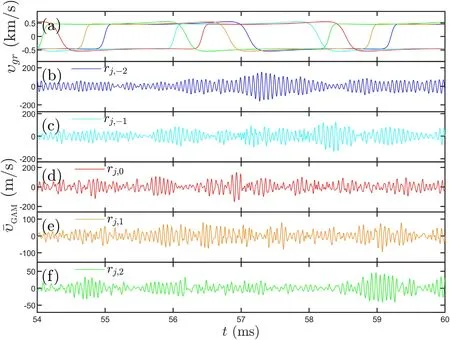
Figure 8.The magnified graphs in 54-60 ms of figure 7 with low frequency portion filtered out.

Figure 9.Frequency-time spectrogram at rj,0.
6.Impact of sign of weak dispersive coefficient on the GAM propagation
The GAM propagation is a hot topic since the first observation in experiments [20, 21] till recently.The observed outward phase velocity seems consistent with the eigenmode theory between edge and WKB turning point in downward temperature profile [22, 33].The corresponding positive dispersive coefficient can only be derived by kinetic model[16, 24, 25] or by fluid model with FLR correction [26], not by fluid model without FLR correction[27,28].On the other hand, the simulations in [27, 28] emphasize the significance of group velocity, rather than phase velocity, because the former is the real physical entity.At this point we would like to point out that the propagation issue is not fully determined by property of media, but also by the way of GAM generation.
The eigenmode solution is the long-time asymptotic solution.In the picture developed in this paper, GAM is generated by Instanton.The spatiotemporal correlation of Instanton and GAM is vividly evident in figures 10-13(a)and(b).The Instanton runs away rapidly.The initial value problem reveals the motion of the GAM so generated.The lifetime of GAM is not long enough to allow eigenmode formation.This may shed light on why GAM propagation may be observed in the simulation of [27, 28].It is fruitful,then, to investigate GAM propagationυGAMunder intermittency environment when there is a single central rational surface.The presentation is organized as follows: (1) the sections 6.1 (6.2) is for a positive (negative) dispersive coefficient, and (2) each one consists of two groups, the first(second) being triggered by inward (outward) moving Instanton.The dynamics of each group is illustrated through four 3D close-up figures: (a) motion of Instanton, (b) spatiotemporal structure ofυGAM,(c) spectrum versus frequency and spatial position, (d) spectrum versus wave number and time.A clarification of nomenclature is in order.The WKB turning point refers solely to eigenvalue problem.For wave propagation the inner (outer) turning point refers to the location of wave reflection where the group velocity reverses sign from inward (outward) to outward (inward).
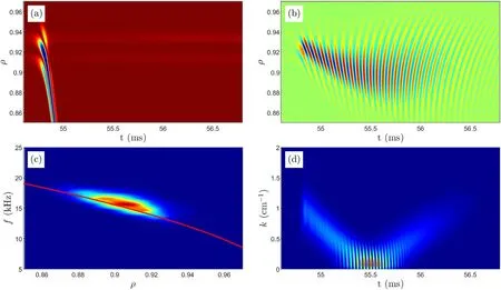
Figure 10.Spatiotemporal structure of (a) drift wave envelope cos2 Θand (b)υGAMfor D (τ e)=1in period of 54.6-56.8 ms and ρ =0.85− 0.97, (c) spectrum versus frequency and spatial position, (d) spectrum versus wavenumber and time.
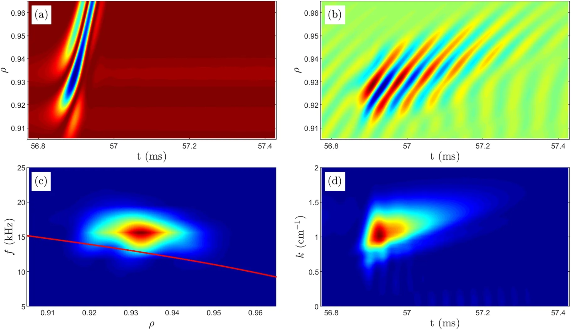
Figure 11.Spatiotemporal structure of (a) drift wave envelope cos2 Θand (b)υGAMfor D (τ e)=1in period of 56.8-57.4 ms and ρ =0.91− 0.96, (c) spectrum versus frequency and spatial position, (d) spectrum versus wavenumber and time.
6.1.D(τe)=1
The data have been presented in figure 4(c).

Figure 12.Spatiotemporal structure of (a) drift wave envelope cos2 Θand (b)υGAMfor D (τ e)= −1in period of 54.6-56.8 ms and ρ =0.86− 0.96, (c) spectrum versus frequency and spatial position, (d) spectrum versus wavenumber and time.

Figure 13.Spatiotemporal structure of (a) drift wave envelope cos2 Θand (b)υGAMfor D (τ e)= −1in period of 56.8-57.7 ms and ρ =0.86− 0.96, (c) spectrum versus frequency and spatial position, (d) spectrum versus wavenumber and time.
(1) The ingoing GAM (being triggered by inward moving Instanton, see figures 6(b), (c) and 10(a)) in period of 54.6-56.8 ms andρ=0.85− 0.97 is displayed in figures 10(b)-(d).Initially both phase velocity and the group velocity are inward (υp<0,υg<0) till hitting the turning point around 55.5 ms.After being reflected,GAM moves outwardly withυp>0andυg>0.This is consistent with gyrokinetic simulations [34-40] and fluid model with FLR correction [41].
(1) The outgoing GAM (being triggered by outward moving Instanton, see figures 6(f), (g) and 11(a)) in period of 56.8-57.4 ms andρ=0.91− 0.96 is displayed in figures 11(b)-(d).Initially both the phase and group velocity of GAM are positive,υp>0andυg>0,which is consistent with gyrokinetic simulation[42, 43].
6.2.D(τe)=−1
Except for the change ofD(τe) from 1 to −1, all other parameters remain intact.They are displayed here in order to compare with simulations using fluid model without FLR correction.The intermittent characteristics of GAM are almost the same as results in figure 2-5.The only difference is the propagation behavior of GAM, phase velocity in opposite direction to group velocity, in contrast to same direction forD(τe)>0.The outward propagating GAM does exist in a negative dispersive media(D(τe) <0);but brought by inward Instanton.In a sense the ‘emergence’ of GAM in simulation for negativeD(τe) has the special theoretical significance.The formation of eigenmode requires two WKB turning points.The linear differential equation is unable to get inner WKB turning point in this case.(1) The activity is triggered by inward moving Instanton(in figure 12(a)).Spatiotemporal structure of GAM in period of 54.6-56.8 ms andρ=0.88− 0.96 is displayed in figures 12(b)-(d).Initially the inward moving Instanton (in figure 12(a)) triggers inward phase velocity (υp<0), but outward group velocity(υg>0), which is consistent with Landau fluid simulation [27, 28].After being reflected at the outer turning point, GAM moves inwardly withυp>0andυg<0.This behavior has not yet been reported in[27, 28], perhaps the signal is too weak to be noticed.Spectrum in figure 12(c) is very similar to figure 10(c)for almost same frequency at turning point and localωG.(1) The activity is triggered by outward moving Instanton(in fgiure 13(a)).Spatiotemporal structure of GAM is displayed in figure 13(b) for 56.8-57.7 ms andρ=0.86− 0.96, the phase and group velocity of GAM are opposite, i.e.υp>0andυg<0.The frequency of GAM is a little smaller than the localωGand does not change as it propagates inwardly as shown in fgiure 13(c).Spectrum in figure 13(d) is very similar to fgiure 11(d).
In summary, forD(τe)=1the data are consistent with simulations based on gyrokinetic model and fluid model with FLR correction; forD(τe)= −1the data in figure 12(b)before 55.5 ms are consistent with results in [27, 28]; no similar data are reported in [27, 28] for either in figure 12(b)after 55.5 ms and in figure 13(b).
7.Conclusions
In this paper the theoretical model for toroidal zonal flow,including both TLFZF and GAM,is systematically developed based on Braginskii model with FLR correction (to weak dispersive coefficient) in tokamak configuration.This model is numerically solved by making use of the ITG mode structure in real configuration (figure 1) on basis of [11] to calculate two important meso-scale physical quantities: Reynolds stress and group velocity of ITG.It reveals four new high-level qualitative features regarding intermittent excitation and propagation of GAM.
(1) The numerical experiment based on the deterministic toroidal zonal flow system, equations (25)-(27) for multiple central rational surface coupling, seems to reproduce many intermittent characteristics of GAM observed in experiments in a variety of tokamaks[1−10].For single central rational surface,equations (18)-(20), however, the intermittent excitation reduces to a series of periodic bursting.The indefinite initial phase difference among multiple central rational surfaces is the likely cause behind the intermittent characteristics.
(2) The GAM generation is triggered when the radial group velocity of the drift wave crosses zero; it is the precise moment for the phase transition from Caviton into Instanton.The pulses brought by rapid motion of Instanton induce resonance to the GAM dispersion.This can be better described in views of single central rational surface.The Instanton immediately runs away and periodic stopping follows as GAM is dissipated until the next occurrence of zero crossing.
(3) Not only GAM generation, but also GAM propagation is highly correlated with the (inward/outward) motion of Instanton.Notice that the GAM propagation phenomenon is the solution of an initial value problem before the system has time to settle into an eigenstate.The initial condition is provided by the motion of triggering Instanton.The GAM (inward/outward)propagation is systematically explored for both positive and negative dispersive coefficients.The results are compared with simulations in both gyrokinetic and fluid models in literature.
(4) We have also noticed that regardless the motion of triggering Instanton,either inward or outward,the GAM phase-group velocity is always in the same (opposite)direction for positive (negative) dispersive mediaD(τe)=1(D(τe)= −1) .In order to determine the sign of dispersive coefficient experimentally, one may have to measure both the phase velocity and the group velocity of GAM simultaneously.Either sign of either velocity may occur for both dispersive coefficients.
Finally, we must apprize the reader of the somewhat limited scope of this paper.Many interesting GAM phenomena observed in experiments-such as ‘continuum’ versus ‘eigenmode’, coexistence of multiple modes, radial extension of ‘eigenmode’ and the scaling law etc-are not discussed here.We have concentrated here (through the numerical solutions of the three equations)only on a subset of GAM related issues.A more complete and systematic exploration(including for example working out the parameter dependences) is deferred to a future paper.Furthermore, an invariant turbulence level was assumed to calculate the time evolution of the system.Since the generated shear flow tends to suppress turbulence,this assumption is not fully valid-we expect quantitative modifications to our results through shear suppression.However,the theory developed in[11]as well as in this paper, limited to the like-mode coupling either in calculation of Reynolds stress and concepts regarding drift wave envelope, will give a qualitative knowledge of the dynamics.Unlike-mode coupling is surely possible and it may lead to new features-a resonant mechanism [44], for instance.
Acknowledgments
The authors would like to acknowledge Dr D F Kong, X H Zhang and M Y Wang for helpful discussion on experimental observations.The present work was supported in part by the National MCF Energy R&D Program of China (Nos.2018YFE0311200 and 2017YFE0301204), National Natural Science Foundation of China (Nos.U1967206, 11975231,11805203 and 11775222), Key Research Program of Frontier Science CAS (QYZDB-SSW-SYS004) and the US Dept.of Energy (No.DE -FG02-04ER-54742).
Appendix A.Conditions for detrapping due to collision and occurrence of ITG in L-mode discharge near tokamak edge
There is circulating a belief that GAM is likely generated by TEM not by ITG mode, because at the tokamak edgeηiis normally less than 2, the threshold for instability.
In fact, in L-mode discharges near tokamak edge, the collision frequency is high enough that particle’s trapping is minimal.Mathematically,this condition translates intoωbτdetrap<1,where the bounce frequencyand the de-trapping timeis the electron thermal speed andis the electron-ion collision frequency,Zeffis the effective ion chargeZ).For typical tokamak geometry and plasma densities, the critical temperature,below which particle trapping is a minor effect,is a few hundred eV[45].Experimental data on a variety of tokamaks studying zonal flows are shown in table A1 (withSinceis true for all cases,the trapped density will most likely be too small to support a TEM.
The case for the ITG turbulence is a little stronger; there are published papers measuring GAMs in which the edgeconditions are suchthat unstable ITG can readily exist.Table A2 lists edge-conditions for four machines; the data sources are: figure 5 of [46] for ASDEX, figure 3 of [7] for DIII-D, figure 15 of [9] for JET,and figure 3 of [10] for EAST.All shots, except for #18813 that provides ion temperature profile, are analyzed by assumingLTi=LTe.

Table A1.Equilibrium parameters of L-mode (Ohmic) discharge in the edge (r /a=0.9) of 7 tokamak machines.

Table A2.ηi in L-mode (Ohmic) discharge near tokamak edge (ρ ≡ r /a ≈0.9) on 4 machines.
Appendix B.Derivation of charge and particle conservation equation for axisymmetric electrostatic mode in meso-scale
In this appendix the derivation of charge and particle conservation for low frequency electrostatic axisymmetric mode,equations (1) and (2) respectively, is presented on basis of Braginskii two-fluid model [17] essentially same as [18], but extended from cold ion to warm ion.
It begins with symbol definition.The quantities having both over-bar and under-tilde stand for fluctuations in mesoscale, while those without overbar and tilde stand for equilibrium with subscripti(e) representing ion (electron).Those quantities having overtilde in lower case stand for fluctuating field in microcopic scale like.u,J,N,Pandφare fluid velocity,current, density, pressure and potential respectively,Π is viscosity tensor,Ris friction force (Ri= −Re),Bis magnetic field,bis the unit vector along the equilibrium magnetic field,Ti,eis ion(electron)temperature,cis the speed of light, andeis the unit electric charge.
The ion momentum equation in meso-scale is obtained by ensemble averaging in micro-scale over the full ion momentum equation containing both micro- and meso- scale[18], provided that the scale separation is valid

To the leading order for low frequency waveswhereis the ion cyclotron frequency, the perpendicular component of equation(B.1)is chosen to be the electrostatic and diamagnetic drift velocity


The electron momentum equation is

The parallel Ohm law can be derived from the parallel component of equation (B.6) straightforwardly by invoking the concept of conductivitywhereis the parallel current fluctuation,Simply,neglecting the electron inertia and viscosity tensor yields

In equation (B.7), the assumed state equation is used.
The one-fluid equation of motion can be derived by adding equation (B.1) to equation (B.6) with dropping electron inertia term and viscosity tensor

In the above manipulations the assumed state equation introduced cut-off to energy conservation.This makes sense provided that the thermal physics merely plays minor role for physics of zonal flow.
The two conservation equations, namely the particle conservation and charge conservation, are originally

and

By taking the vector product of equation (B.8) withB, we obtain

In equation (B.11)the polarization drift inproportional to(ω/ωci)2has been neglected.
Since the term

can be neglected for low-βplasmas [50] (βis the ratio of thermal pressure to magnetic pressure),the main contribution to divergence of diamagnetic current comes from the curvature of magnetic field in tokamak.However,the perpendicular viscosityhas to be retained for numerical computation.For the divergence of linear and nonlinear polarization current, curvature effect can be neglected becausewhereκ∣ ∣and ∇∣ ∣correspond to equilibrium scale and mesoscale respectively forwhich is the curvature of magnetic field.Substituting the divergence of equation (B.7) and (B.11) into(B.10) yields charge conservation equation

Similar procedure is adopted for obtaining the divergence ofSubstituting it into equation (B.9) yields particle conservation equation

The parallel component of equation (B.8) is

In terms of the dimensionless quantities,and definingthe two conservation equations in toroidal coordinate system(r,ϑ,ς) can be readily obtained for axisymmetric zonal flow on basis of equations (B.13)-(B.15)by invokingradial variation is much faster than poloidal variation.The leading order term of perpendicular viscosity is

Charge conservation equation is
Particle conservation equation is
Appendix C.Poloidal moments of Reynolds stress
In this appendix, the methodology of [30] is adopted to calculate analytic formulae of poloidal moments of Reynolds stress induced by ITG micro-turbulence

the same as equation (17) in section 2.For reader’s convenience, the symbols are the same as those in [30]throughout this appendix, where the 2D mode structure is

The methodology used in [30] has been numerically verified by comparing the results of the analytic formula with the direct numerical integral of equation (C.1) forK(ϑ) :=1satisfactorily [30].
Substituting equation (C.2) into equation (C.1) yields
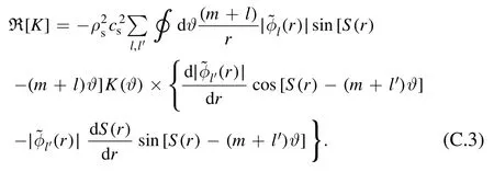
This form will be simplified by defining two new functions
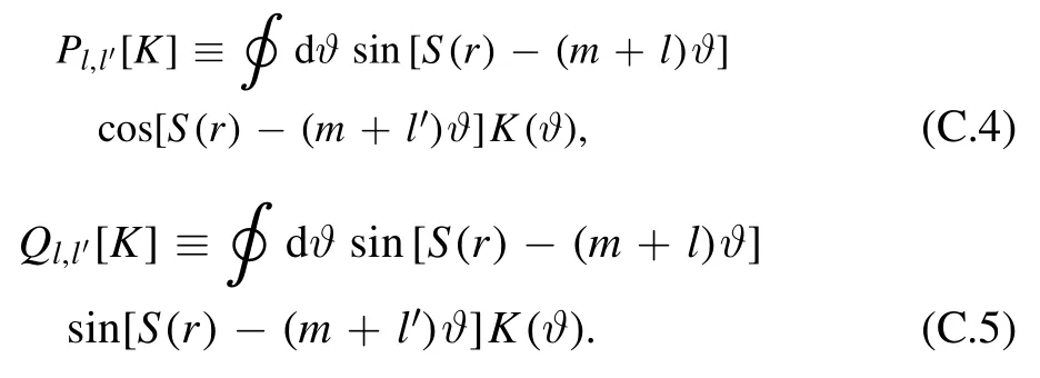
For micro-turbulencem≫1, integral of high order harmonic vanishes, equations (C.4) and (C.5) become

For the kth order sinusoidal harmonic

For the kth order cosinoidal harmonic

Substituting equations(C.4)and(C.5)into equation(C.3)yields

Cosinoidal moment of Reynolds stress:

Sinusoidal moment of Reynolds stress:

Some factors in equations(C.10),(C.11)can be found in[30].They are
In equation (C.15) ‘~’ denotes that a constant factor before Γ(x) is not important and neglected

In equation (C.16)
Now,we are ready to calculate equations(C.10),(C.11).Equation (C.13) is used to obtain

From equations (C.15) and (C.16), we obtain

Multiplying equation (C.17) by (C.18) yields

with


In equation (C.21)

The functionΠp=0,k(x)has been discussed in the appendix B in[30]in detail,and is shown close to a constant forThis is still true for other integer p, because the translational invariance of this function is independent of p.Neglecting the small variation ofΠp,k(x) ,equation (C.19) becomes


in whichcan be equivalently replaced by the operator
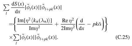
Substituting equation (B.23) into (B.25), then into equation(C.10),the analytic expression of cosinoidal moment of Reynolds stress is found to be
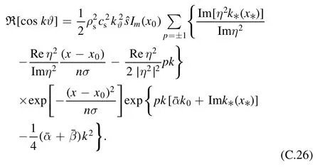
For =k0, equation (B.26) becomes

which is the same result as equation (42) in [30].
The analytic expression of sinusoidal moment of Reynolds stress can be obtained similarly as
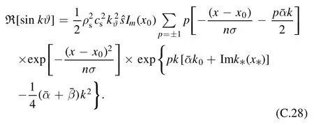
Both the cosinoidal and sinusoidal moments are composed of a monopole and a dipole.However,the dipole is much larger t han the monopole for cosinoidal moment, sinceis small.But for sinusoidal moment, the monopole structure looks more apparent.
Appendix D.TLFZF equation and GAM dispersion
As stated in the introductory section,the framework of the present paper in studying GAM is the extension of equations of [11] to include toroidal coupling of the first harmonic sinusoidal component of sound wave owing to geodesic curvature.A question may arise from the concerns how far the toroidal coupling would modify the model used in[11].Whether or not so many features derived in [11] regarding LFZF might survive etc.The quick answer is that in the low frequency limit the toroidal effect on the TLFZF branch is simply a quantitative change of the inertia of zonal flow as shown below.Since a free parameteraneohas been introduced in[11]to get the theory suitable for various models of zonal flow inertia, the results obtained in [11] are still valid.
Equations(18),(19)can be merged into a single equation by eliminating
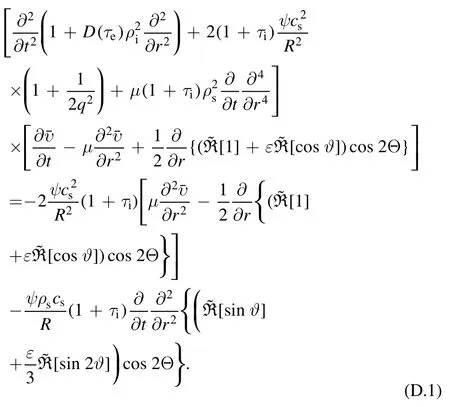
In low frequency limit, the temporal derivative in the first term can be neglected, which reduces equation (D.1) to be
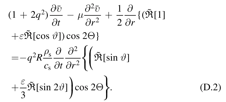
Since the right hand side of equation(D.2)is associated with a low frequency,and the toroidal correction is associated with a small parameterε, we readily obtain the final equation for the low frequency branch by neglecting these small quantitative corrections

It is precisely the leading order equation of TLFZF under fluid model in simple tokamak configuration.Compared to equation (19) of [11],
The GAM dispersion relation can be obtained from lefthand side of equation (D.1)

In the local Fourier representation

杂志排行
Plasma Science and Technology的其它文章
- Numerical simulation of laser-induced plasma in background gas considering multiple interaction processes
- Kinetic-theory-based investigation of electronegative plasma-wall transition with two populations of electrons
- Investigation of the fast magnetosonic wave excited by the Alfvén wave phase mixing by using the Hall-MHD model in inhomogeneous plasma
- Experimental study of sheath potential coefficient in the J-TEXT tokamak
- Nonlinear evolution and secondary island formation of the double tearing mode in a hybrid simulation
- Experimental study of ELM-induced filament structures using the VUV imaging system on EAST
