Polarization manipulation of bright-dark vector bisolitons∗
2021-03-19YanZhou周延XiaoyanLin林晓艳MeisongLiao廖梅松GuoyingZhao赵国营andYongzhengFang房永征
Yan Zhou(周延), Xiaoyan Lin(林晓艳), Meisong Liao(廖梅松),Guoying Zhao(赵国营), and Yongzheng Fang(房永征),‡
1School of Science,Shanghai Institute of Technology,Shanghai 201418,China
2Key Laboratory of Materials for High Power Laser,Shanghai Institute of Optics and Fine Mechanics,Chinese Academy of Sciences,Shanghai 201800,China
3School of Materials Science and Engineering,Shanghai Institute of Technology,Shanghai 201418,China
Keywords: polarization manipulation, vector bisoliton, polarization-locking, group-velocity-locking, linear birefringence
1. Introduction
Optical solitons have potential applications in the fields of optical communications and optical information processing.[1-3]Passively mode-locked ultrafast fiber laser is often constructed to study soliton dynamics.[4-7]More often,vector soliton can be generated in fiber laser because the intrinsic linear birefringence of the single-mode fiber, which is brought by strain, temperature variation, and fabrication imperfection. In theory, the vector soliton in a dissipative fiber laser system can be well described using coupled Ginzburg-Landau equations, which include fiber dispersion, gain, loss,self-phase modulation, cross-phase modulation, coherent energy coupling, gain bandwidth, and so on.[1,6]In experiment,different kinds of vector solitons can be generated through changing intra-cavity linear birefringence and pump power,such as group-velocity-locked vector soliton (GVLVS),[9-11]polarization-locked vector soliton(PLVS),[12,13]and polarization rotation vector soliton (PRVS).[14]For GVLVS, the two orthogonal polarization modes will shift their central wavelengths in opposite directions and copropagate as a unit without splitting. PLVS has fixed polarization state (±π/2 phase difference in orthogonal polarization directions) and orthogonal polarization modes have the same central wavelength.PRVS has fixed soliton intensity accompanied with periodically evolving polarization state, and the evolving period is multiple of intra-cavity pulse transmission period.
Vector solitons with different pulse shapes properties have also been reported, such as bright-bright vector soliton, bright-dark vector soliton, and dark-dark vector soliton. Among them, the bright-dark vector soliton has one pulse peak in one polarization direction and one dip in the orthogonal polarization direction. It can exist in normal or anomalous dispersion regime,which is different from its scalar counterpart.[15,16]
Until now, there have been many reports about vector solitons at different wavelengths. Out-cavity polarization manipulation of vector solitons has also been reported. For example, Jin et al. theoretically and experimentally demonstrated the manipulation of GVLVS in an Er-doped passively mode-locked fiber laser system, and finally generated “2+1”and “2+2” type pseudo-high-order GVLVSs.[17,18]Wang et al. numerically analyzed the decomposition and recombination of group-velocity-locked vector dissipative solitons.[19]Zhu et al. experimentally showed the generation of high-order vector soliton structure based on group-velocity-locked vector dissipative solitons.[20]In our previous work,we theoretically simulated the polarization manipulation of PLVS with super-Gaussian pulses,[21]dark-dark vector solitons,[22]bright-dark vector solitons,[16]parabolic vector solitons,[23]and vector bisolitons[24]at 1-µm wavelength regime. However, there are few reports about polarization manipulation of bright-dark vector bisolitons. In this work, we theoretically simulate the polarization manipulation of polarization-and group-velocitylocked bright-dark vector bisolitons in a polarization-resolved fiber system at 1-µm wavelength regime. It is found that different kinds of pulse shapes and corresponding optical spectra can be generated through changing the pulse parameters of the orthogonal polarization modes. Our simulation results can provide beneficial evidence for the study of manipulating vector multi-solitons.
2. Theoretical model and simulation
Figure 1 shows the theoretical model in our simulation.Input vector bisoliton with amplitudes of A1and A2in vertical and horizontal directions suffers from amplitude ratio(A2/A1)change,time delay(ΔT)change,and linear birefringence(Δn)change one by one. At last,the modulated vector bisoliton is collimated by the collimator (Col) and incident on the polarization beam splitter(PBS).The two orthogonal electric fields are separated by the PBS in orthogonal transmission directions. In experiment,A2/A1can be changed by a fiber amplifier or fiber attenuator,ΔT can be tuned with a fiber time delay line,Δn is changed by rotating the polarization controller(PC),and projection angle θ is achieved through rotating PBS.

Fig.1. Theoretical model in the simulation.
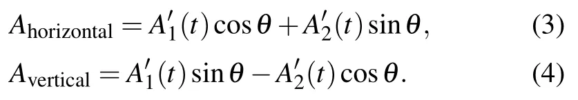
The electric fields before the PBS can be written as
After the PBS, the projected horizontal mode Ahorizontaland vertical mode Averticalare
In later simulations,we assume T1=T2=5 ps,Tinterval=20 ps. It should be noted that here we do not consider dispersion and nonlinearity in the single-mode fiber in our model,because we assume that the fiber length is much shorter compared with the dispersion length and nonlinearity length. The fiber dispersion length can be increased through reducing the net group-velocity dispersion (with fixed pulse width), while the fiber nonlinear length can be increased by decreasing the pulse peak power. Of course, we can replace the piece of single-mode fiber and the imposed PC by several waveplates to change the linear birefringence,but it will broke the all-fiber structure.
2.1. With the same central wavelength
In this section, we consider the vector bisoliton with the same central wavelength λ1=λ2=1064 nm, which can be generated in the Yb-doped passively mode-locked vector bisoliton fiber laser. In the first three cases,Δϕ is fixed at π/2 because it is the characteristic of PLVS.In the last case,Δϕ is varied from 0 to π through gradually rotating the PC.
Firstly,the amplitude ratio is changed for simulation.Figure 2 gives the simulated temporal pulse shapes and corresponding optical spectra when amplitude ratio A2/A1is 1/1.5,1/1.2, 1/1, 1.2/1, and 1.5/1 respectively. While the other parameters are θ =0◦,ΔT =0 ps,and Δϕ=π/2. In Figs.2(a)-2(e),we can see that as A2/A1increases,there are always two pulse peaks in the horizontal direction and only one broad dip in the vertical direction. Also,the dip depth has an obvious increase when A2/A1reaches 1.2/1.In the corresponding optical spectra shown in Figs.2(f)-2(j),both orthogonal polarization modes have only one peak, and the peak intensity of the vertical mode is always higher than that of the horizontal mode,although the amplitude ratio is smaller than 1.

Fig.2. Modulated temporal pulse shapes (a)-(e) and corresponding optical spectra (f)-(j) in horizontal and vertical polarization directions when the amplitude ratio is changed.
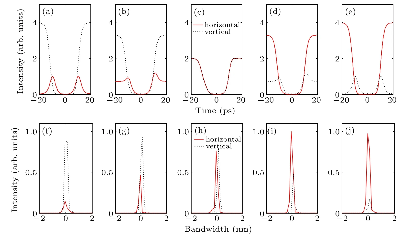
Fig.3. Modulated temporal pulse shapes (a)-(e) and corresponding optical spectra (f)-(j) in horizontal and vertical polarization directions when the projection angle is changed.
Then, the projection angle is varied for simulation. Figure 3 gives the simulated temporal pulse shapes and corresponding optical spectra when θ is 5◦, 25◦, 45◦, 65◦, and 85◦respectively. The other parameters are A2/A1= 1/1,ΔT =1 ps, and Δϕ =π/2. In Figs. 3(a)-3(e), there are two peaks in the horizontal/vertical mode and one dip in the vertical/horizontal mode when θ is smaller/larger than 45◦. And there is only one broad dip for the orthogonal polarization modes and they are coincide with each other when θ =45◦under symmetry projection.In the corresponding optical spectra shown in Figs.3(f)-3(j),the central wavelengths of the orthogonal polarization modes are slightly different. The horizontal/vertical mode has blue/red shift accompanied with peak intensity variation, which may be due to the energy transfer between the two orthogonal modes. So “1+1” fundamental dark-dark and“2+1”pseudo-high-order bright-dark GVLVSs can be generated through changing θ. The difference between high-order vector soliton and pseudo-high-order vector soliton is that the phases in the orthogonal polarization directions are locked/unlocked for the high-order vector soliton/pseudohigh-order vector soliton.
After that,the time delay change is considered in simulation. Figure 4 shows the temporal pulse shapes in the orthogonal polarization directions when the time delay is increased from 2 ps to 20 ps with 2 ps time interval. The other parameters are A2/A1=1/1, θ =43◦, and Δϕ =π/2. We can see that there is only one broad dip in the orthogonal polarization directions when ΔT =2 ps,and another dip will appear when ΔT reaches 4 ps. The dip depths of these two dips become equal when ΔT =10 ps. Besides, there is a new pulse peak at the position of continuous wave background when ΔT starts with 2 ps,and the peak intensity of the vertical mode is always higher than that of the horizontal mode. The two orthogonal modes have similar pulse shapes near peak/dip position but with obvious different continuous wave backgrounds. In the corresponding optical spectra demonstrated in Fig.5,the optical spectrum splits for the orthogonal polarization modes when ΔT increases from 2 ps to 14 ps,and there are side peaks when ΔT is larger than 14 ps. The maximum peak intensity of the horizontal mode decreases with increased time delay. While for the vertical mode,the maximum peak intensity is relatively steady with increased time delay.

Fig.4. Modulated temporal pulse shapes in horizontal and vertical polarization directions when the time delay is changed.
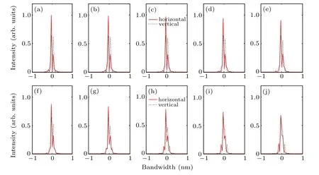
Fig.5. Optical spectra corresponding to Fig.4.
At last,we consider the case when the phase difference is 0,π/4,π/2,3π/4,and π,and the simulation results are shown in Fig.6.The other parameters are A2/A1=1/1,θ =45◦,and ΔT =0 ps. We can see that the optical spectra of the orthogonal modes are coincide with each other but the pulse shapes are not when Δϕ is 0 or π. While the pulse shapes of the orthogonal modes are coincide with each other but the optical spectra are not(with different central wavelengths and different peak intensities) when Δϕ is π/2. There is only one dip for the orthogonal modes when Δϕ is π/4,π/2,or 3π/4,and two dips when Δϕ is 0 or π/2. Besides,another peak appears when Δϕ is not equal to π/2.

Fig.6. Modulated temporal pulse shapes (a)-(e) and corresponding optical spectra (f)-(j) in horizontal and vertical polarization directions when the phase difference is changed.
2.2. With different central wavelengths
In this section, we simulate the polarization manipulation of bright-dark vector bisoliton with different central wavelengths (λ1=1063 nm, λ2=1065 nm), and it is the characteristic of GVLVS.Because GVLVS has unfixed phase difference,in the first three cases we assume Δϕ =0 for simplicity.In the last case, Δϕ is varied from 0 to π through gradually rotating the PC.
Similar to Subsection 2.1, firstly we simulate the output pulse shapes and optical spectra when the amplitude ratio is changed. Figure 7 gives the simulated temporal pulse shapes and corresponding optical spectra when amplitude ratio A2/A1is 1/1.5, 1/1.2, 1/1, 1.2/1, and 1.5/1 respectively. While the other parameters are θ =0◦, ΔT =0 ps, and Δϕ =0. We can see that as the amplitude ratio increases, the horizontal mode and vertical mode always have two peaks and two dips,respectively. In the corresponding optical spectra shown in Figs.7(f)-7(j),both orthogonal modes have only one peak and the peak intensity of the vertical mode is always higher than that of the horizontal mode regardless of the amplitude ratio.So“2+2”pseudo-high-order bright-dark GVLVS is generated in this situation.

Fig.7. Modulated temporal pulse shapes (a)-(e) and corresponding optical spectra (f)-(j) in horizontal and vertical polarization directions when the amplitude ratio is changed.

Fig.8. Modulated temporal pulse shapes (a)-(e) and corresponding optical spectra (f)-(j) in horizontal and vertical polarization directions when the projection angle is changed.
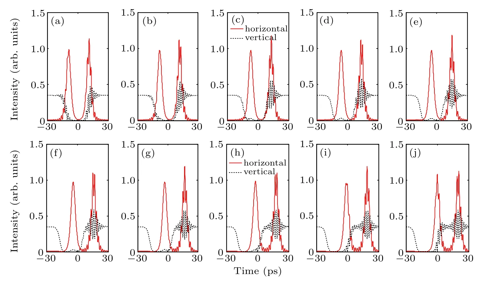
Fig.9. Modulated temporal pulse shapes in horizontal and vertical polarization directions when the time delay is changed.
Then, we consider the case of changing projection angle. Figure 8 gives the simulated temporal pulse shapes and corresponding optical spectra when θ is 5◦, 25◦, 45◦, 65◦,and 85◦respectively. The other parameters are A2/A1=1/1,ΔT = 1 ps, and Δϕ = 0. The horizontal/vertical mode has multiple side peaks/dips when θ is 5◦,and the result becomes contrary for the orthogonal polarization modes when θ is 85◦.And the peak/dip oscillation will become higher when θ is approaching 45◦. The temporal pulse oscilloscopes of the orthogonal modes will become the same when θ is 45◦. In the optical spectra shown in Figs. 8(f)-8(j), the peak intensity of longer wavelength is always higher than that of shorter wavelength,and there are two peaks in the horizontal/vertical mode when θ is 25◦/65◦. In this case,most energy is concentrated at longer wavelength although A2/A1=1/1.
After that, we simulate the output pulse shapes and optical spectra when the time delay changes from 2 ps to 20 ps with 2 ps time interval. The other parameters are A2/A1=0.3/1,θ =10◦,and Δϕ=0. Figures 9 and 10 show the simulation results. In Fig.9,for the horizontal mode,there are two pulse peaks,and the lagged pulse has obvious temporal oscillations across the entire pulse. While for the vertical mode,there is only one broad pulse dip, and the trailing pulse edge has chirp-like oscillations. The broad pulse dip has slight split when ΔT changes from 6 ps to 14 ps. The time interval of the orthogonal modes increases with increased ΔT. Figure 10 demonstrates the optical spectra corresponding to Fig.9. It shows that with the increase of ΔT, there is always one peak located at shorter/longer wavelength position for the horizontal/vertical mode,and there is another peak with much smaller peak intensity located at longer/shorter wavelength position for the horizontal/vertical mode. The main peak intensity of the vertical mode is much higher than that of the horizontal mode, and the peak intensity of the orthogonal modes has a slight decrease with increased ΔT.
At last, we simulate the temporal pulse shapes and corresponding optical spectra when Δϕ is 0, π/4, π/2, 3π/4,and π respectively. The other parameters are A2/A1=0.3/1,θ=1◦,and ΔT =0 ps.Figure 11 shows the simulation results.We can see that the smooth temporal pulse shapes and optical spectra do not have obvious changes when Δϕ is changed,which means that the output“2+1”pseudo-high-order brightdark GVLVS is insensitive to the change of phase difference.In the optical spectra shown in Figs.11(f)-11(j),the horizontal mode is located at 1061 nm and there are two side peaks.While the vertical mode is located at 1067 nm with one sharp peak, and the peak intensity of the vertical mode is always higher than that of the horizontal mode although the input amplitude ratio is 0.3.

Fig.10. Optical spectra corresponding to Fig.9.
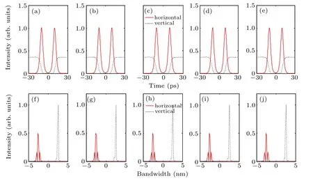
Fig.11. Modulated temporal pulse shapes(a)-(e)and optical spectra(f)-(j)in horizontal and vertical polarization directions when the phase difference is changed.
3. Conclusion
We simulated the polarization manipulation of 1-µm polarization- and group-velocity-locked bright-dark vector bisolitons in a polarization resolved optical fiber system. In the simulation, through changing the amplitude ratio, projection angle, time delay, and phase difference of the orthogonal polarization modes,different kinds of vector solitons were generated in orthogonal polarization directions,such as“1+1”fundamental dark-dark GVLVS,PLVS with two dips and one peak in orthogonal polarization directions, “2+1” and “2+2”pseudo-high-order bright-dark GVLVSs. Also,GVLVSs with multiple temporal oscillations could be generated with appropriate pulse parameters. Our simulation can provide beneficial conduct for manipulation of vector multi-solitons.
杂志排行

Chinese Physics B的其它文章
- Nonlocal advantage of quantum coherence in a dephasing channel with memory∗
- New DDSCR structure with high holding voltage for robust ESD applications∗
- Nonlinear photoncurrent in transition metal dichalcogenide with warping term under illuminating of light∗
- Modeling and analysis of car-following behavior considering backward-looking effect∗
- DFT study of solvation of Li+/Na+in fluoroethylene carbonate/vinylene carbonate/ethylene sulfite solvents for lithium/sodium-based battery∗
- Multi-layer structures including zigzag sculptured thin films for corrosion protection of AISI 304 stainless steel∗