Multi-layer structures including zigzag sculptured thin films for corrosion protection of AISI 304 stainless steel∗
2021-03-19FatemeAbdi
Fateme Abdi
Department of Engineering Sciences,Faculty of Advanced Technologies,University of Mohaghegh Ardabili,Namin,Iran
Keywords: corrosion protection,multilayer,zigzag thin film,EIS,equivalent circuit
1. Introduction
AISI 304 stain less steel has many applications in industry and technology due to its good mechanical properties and good corrosion resistance. However, this substance does not have high resistance to corrosion in the environments containing aggressive ions, such as Cl−and S−2, especially at high temperatures, and environments with very high or very low pHs.[1-3]Therefore,improving the corrosion resistance of this widely used substance is a fundamental requirement. So far,many methods have been employed to increase the corrosion resistance of the AISI 304 stainless steel. The previous older methods such as painting have been extensively used due to the good adhesion of paints to steel.[4]Paint is a thick coating, and the use of thin coatings to protect steel from corrosion is very essential. To do so, ion implantation,[5]arc ion plating,[6]sol-gel coating,[7,8]chemical deposition,[9]and physical depositions[5,10,11]have been used. The advantage of using physical depositions is that the layers are more controllable. In the previous study, the researchers used a physical coating to form multilayer structures on steel and revealed that the application of manganese nitride multilayer structure instead of the monolayer structure significantly increased the corrosion resistance.[12]The very purpose of the present study is to improve multilayer structures,for which the zigzag structure is used in the multilayer thin films.
2. Experiment
Sheets of AISI 304 stainless steel with dimensions of 20 mm×20 mm×1 mm and the compounds listed in Table 1 were considered as substrates. To begin with, all substrates were first cleaned in acetone, in alcohol, in in ultrasonic bath in sequence. Then, the substrates were glued to the substrate holder with a special vacuum adhesive. Manganese was considered as the protecting material,and the deposition was performed by using An Edwards(Edwards E19 A3)machine and electron beam at room temperature with a base pressure of 2×10⁻⁷Torr (1 Torr=1.33322×10²Pa) over four steps.At each step of the deposition, thin films of manganese with 55-nm thickness were formed, so that the total thickness of the manganese thin films on the substrate was 220 nm. In the four-step deposition process,there is a 15-min interval between two depositions. The purpose of this interruption was to cool the previous layer and stabilize the grains. Figure 1(a)demonstrates the mentioned four-layer structure(conventional multilayer thin film).

Table 1. Chemical compositions of AISI 304-type stainless steel used in this work.
The next task was to deform the middle layers (layers 2 and 3). To do so, first a 55-nm-thin film of manganese was formed on a substrate. Then, a 110-nm zigzag structure was formed on the previous thin film,and finally a 55-nm-thin film of manganese was formed on this zigzag structure by returning the substrate to its original state. To form the zigzag structure,after forming the conventional 55-nm-thin film, the substrate was placed at an angle of 20◦relative to the line perpendicular to the substrate,and this structure is called zigzag 1 structure for short. Figure 1(b)shows this structure.
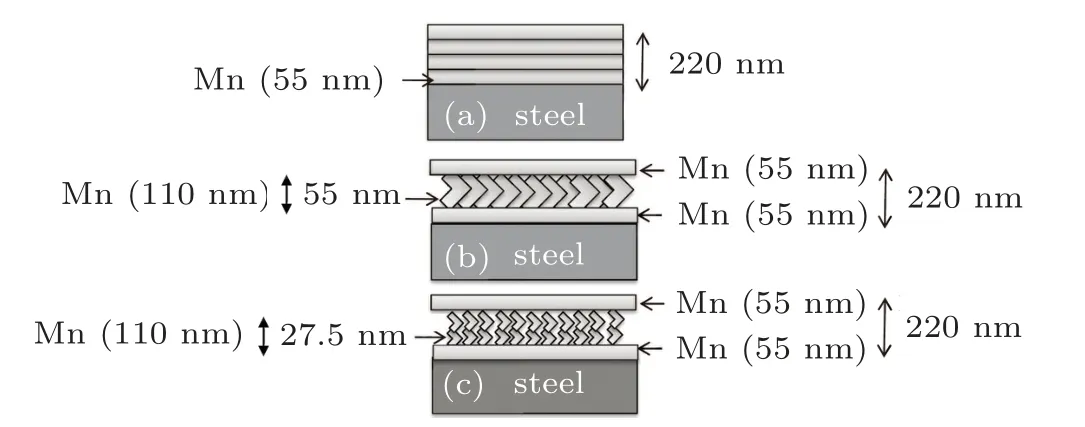
Fig.1. Schematic diagram of(a)conventional multilayer thin film,(b)multilayer thin film with zigzag 1 structure, and (c) multilayer thin film with zigzag 2 structure.
To better investigate the effect of the geometry on the protection against corrosion,the other task was to convert each of zigzag arms into a zigzag structure. That is, after depositing a 55-nm-thin film, the zigzag structure was formed twice so that the thickness of each zigzag arm was 27.5 nm, and the total thickness of the middle layer(two zigzag structures containing 4 arms) was 110 nm. Finally, a 55-nm-thin film was deposited on them. Figure 1(c)shows a schematic representation of this design. This structure is called zigzag 2 structure for short.
After forming the conventional multilayer thin films,zigzag 1 and zigzag 2 structures, their nitriding process was performed by using a furnace (Exciton, 1200-30/6, T.H, Iran equipped with Shinko temperature programmable controller- PCD33A). To do so, the samples were annealed with a 400-sccm nitrogen flux at 623 K.The annealing processes consisted of the following three stages:
Stage AIt took an hour for the temperature to reach 623 K(in steps of 6◦C per min).
Stage BThe samples were kept at this temperature for 4 h.
Stage CThe device was turned off to cool down to temperature slowly from 623 K to room temperature.
In all the above-mentioned stages, the nitrogen flux passed through the samples.
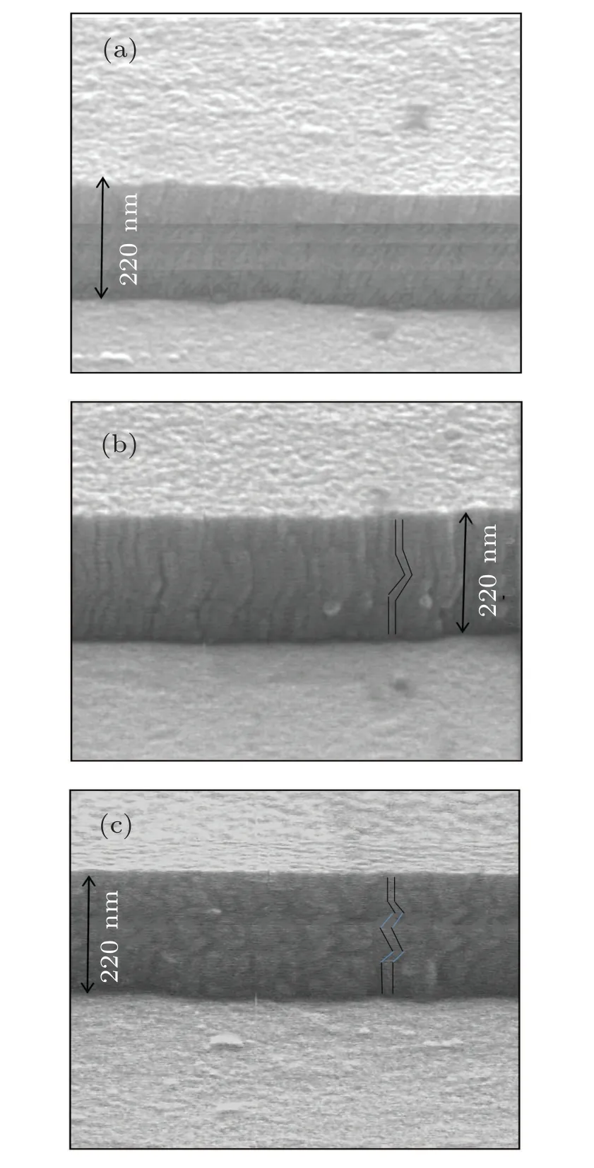
Fig.2. The FESEM image of(a)conventional multilayer thin film,(b)multilayer thin film with zigzag 1 structure, and (c) multilayer thin film with zigzag 2 structure.
The film thickness and cross sections of structures were observed by field emission scanning electron microscope(FESEM)(Hitachi S-4100 SEM,Japan). Figures 2(a)-2(c)show the FESEM images of the conventional multilayer thin film,zigzag 1 structure,and zigzag 2 structure respectively. To ensure the formation of manganese nitride phase and to investigate the crystallinity degree of the samples, x-ray diffraction(XRD) analysis was performed (model STADI MP Diffractometer, Germany (Cu-Kαradiation) in steps of 0.01◦and count time of 1.0 s per step),In addition,the surface morphology of samples was examined by using an atomic force microscope(AFM)(Nt-mdt scanning probe microscope,BL022,Russia; with low stress silicon nitride tip of less than 200 ˚A in radius and tip opening of 18◦). Polarization test was performed to determine the corrosion rate and tendency. Furthermore, the electrochemical impedance spectroscopy(EIS)test was performed to investigate the corrosion resistances of different structures by using a three-electrode cell and the Ivum state model of Potentiostat device made by Ivum Company.The 3.5%NaCl solution was considered as the corrosive solution. Furthermore,the AgCl solution,reference electrode,and platinum electrode were used as auxiliary electrodes.
The samples were placed in the fixture as a working electrode in such a way that only a circle with a diameter of 1 cm of the samples was exposed to the corrosive environment. Polarization measurements were performed at potentials ranging from −1 V to 2 V at a rate of 50 mV/s. Moreover,the EIS test was performed in a frequency range from 1 kHz to 0.01 kHz with a voltage range of 0.01 V.Prior to the measurement,the samples were placed in the solution for 0.5 h to stabilize the open circuit potential (OCP). After performing the corrosion test,the SEM images were taken from the samples to observe the surface.
3. Results
3.1. XRD results
Figures 3(a) and 3(b) indicate the XRD results of the 304 stainless steel as compared with the XRD of multilayer structures (conventional multilayer thin film, zigzag 1 structure, and zigzag 2 structure) before and after annealing at nitrogen flux, respectively. As the figures reveal that the XRD spectra of the 304 stainless steel have four peaks,which are located at 2θ =43.7◦,2θ =50.7◦,2θ =74.8◦,and 2θ =90.8◦which represent the γ-Fe (111), γ-Fe (200), γ-Fe (220), and γ-Fe(311)phases,respectively.
Figure 3(a) demonstrates that in the XRD spectrum of the multilayer structures (conventional multilayer thin film,zigzag 1 structure and zigzag 2 structure), in addition to the peaks related to the substrate,namely the phases γ -Fe(200),γ -Fe (220), and γ -Fe (311), other peak is located at 2θ =43.03◦, which represents the crystallographic orientation of Mn(330)(according to the standard card 00-020-0180).
Figure 3(b)indicates that the XRD spectrum of the conventional manganese multilayer thin film does not change much in the nitrogen flux. Only the Mn (330) peak intensity increases slightly due to the grain growth as a result of annealing,and no phase of manganese nitride is observed. However,unlike this structure,the zigzag multilayer structure(zigzag 1 structure and zigzag 2 structure) has a peak at 2θ =40.44◦,which indicates the formation of manganese nitride phase and represents the Mn4N (111) crystallographic orientation (according to the standard card 00-001-1202). The formation of the nitride phase in this structure can be attributed to the porosity nature of the sculptured thin film and the better possibility of reaction and nitride formation. Figure 3(b) shows that the magnesium nitride phase intensity,for the zigzag 2 structure is less than the zigzag 1 structure. The reason is due to the small zigzag arms of this structure.
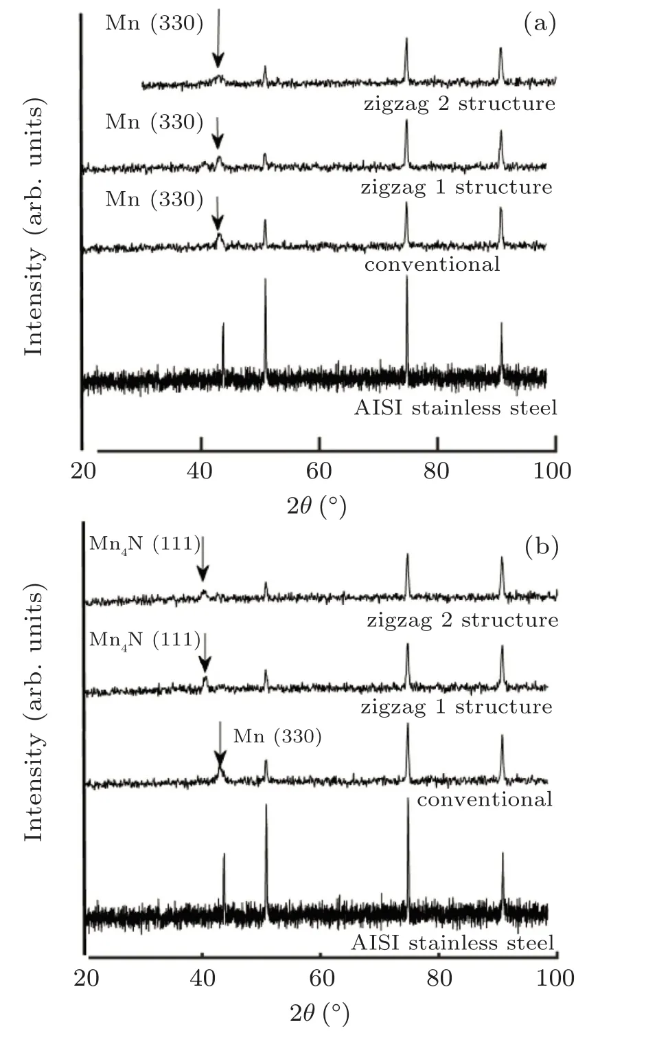
Fig.3. XRD patterns of AISI 304 stainless steel, conventional multilayer thin film, multilayer thin film with zigzag 1 structure, and multilayer thin film with zigzag 2 structure,before(a)and after(b)annealing.
3.2. AFM results
The surface morphology of the conventional multilayer thin film and zigzag multilayer structures (zigzag 1 structure and zigzag 2 structure)is investigated after annealing in nitrogen flux,by using the atomic force microscopy(AFM).

Fig.4.The 2D and 3D AFM images of(a)conventional multilayer thin film,(b)multilayer thin film with zigzag 1 structure,and(c)multilayer thin film with zigzag 2 structure.
Figure 4 demonstrates the two-dimensional (2D) and three-dimensional(3D)images of these samples.As the figure evidently indicates,the sample with the zigzag 1 structure has a smaller grain size than that of the conventional multilayer sample.
In addition,the sample with zigzag 2 structure has smaller grains than the sample with zigzag 1 structure, which can be attributed to the shadowing effect in the glancing angle deposition.
The reason why the smaller grain sizes can change the geometry of thin film from the conventional multilayer thin film into zigzag 1 and zigzag 2 structures can be explained as follows:
(i) The conventional multilayer thin film consists of four 55-nm-thick layers with the least porosity, so the possibility with which the diffusion process takes place in this structure during the annealing is high and large columns might be formed in this process.
(ii) Compared with the conventional multilayer thin film,zigzag 1 structure has high porosity, which reduces its grain size. Thus the diffusion process will be less effective.
(iii) Zigzag 2 structure has higher porosity and smaller grains than the previous two structures due to the shortness of the columns, with the thickness of the middle layer being smaller.
In fact, the grain size increases with thickness increasing. So, conventional multilayer structures and zigzag structure 1 have larger grains than zigzag 2 structure due to their longer arm length in each step of deposition. Average grain size(DAFM), average surface roughness(Rave), and deviation from the mean(Rms)obtained by using Nova software are presented in Table 2.

Table 2. Details of experimental results for AISI 304 stainless steel.
As figure 3 indicates, the reason for the reduction in nitride phase intensity by converting zigzag 1 structure into zigzag 2 structure is due to the shrinkage of the grains in this process.
3.3. Corrosion results
3.3.1. Polarization test results
Figure 5 shows the polarization curves of conventional multilayer thin film and zigzag structures (zigzag 1 structure and zigzag 2 structure)in a 3.5%salt solution. The corrosion current and corrosion potential obtained from these curves(using the Tafel slope) are given in columns 5 and 6 of Table 2, respectively. The results reveal that the zigzag multilayer structures(zigzag 1 and zigzag 2 structures)have higher corrosion potential and lower corrosion current than the conventional multilayer thin film.Given that the current corrosion and the potential corrosion control the corrosion rate and corrosion tendency,respectively,the zigzag multilayer structures have a lower corrosion tendency and corrosion rate than that of the conventional multilayer thin film due to the formation of the nitride phase.
As figure 5 indicates,the zigzag 2 structure has the lowest corrosion current,the highest corrosion potential,and thereby resulting in the highest corrosion resistance. Considering the fact that this structure has a lower nitride phase intensity than that of the zigzag 1 structure,the reason for the higher corrosion resistance,in addition to the nitride phase formation,can be attributed to the geometry of the zigzag 2 structure and the greater number of interfaces, which will be further explained in the subsection of the EIS results.

Fig.5. Potentiodynamic polarization curve of conventional multilayer thin film, multilayer thin film with zigzag 1 structure, and multilayer thin film with zigzag 2 structure.
3.3.2. EIS test results
The Nyquist curves of the conventional multilayer thin film structure and the zigzag multilayer structures (zigzag1 and zigzag 2 structures)are presented in Fig.6.

Fig.6. Experimental Nyquist diagram of conventional multilayer thin film,multilayer thin film with zigzag 1 structure, and multilayer thin film with zigzag 2 structure.
This figure demonstrates that the Nyquist curve of the conventional multilayer thin film has an inductive loop that occurs at low frequencies. The above-mentioned inductive behavior indicates the production of corrosion products and the formation of salt on the sample surface through the pitting of Chlorine ions on the sample surface.[13-17]The mentioned behavior is not observed in the Nyquist curves of zigzag structures. The comparison between Nyquist curves reveals that zigzag 1 structure has a better corrosion resistance than the conventional multilayer thin film due to the presence of nitride phase in this structure. Moreover, the results show that zigzag 2 structure has a much higher corrosion resistance than zigzag 1 structure. The mentioned finding can be attributed to the zigzag geometry of this structure.The equivalent circuit of these structures is provided to better evaluate the EIS results of different multilayer structures.
Figure 7 shows the equivalent circuits for the conventional and zigzag multilayer structures(zigzag 1 and zigzag 2 structures). In these circuits, Rsis the resistance of the solution,L is the coefficient related to the inductive behavior,and CC1,2is the capacitance related to the coating and is observed in incomplete coatings where the solution penetrates the coating. Subscripts 1 and 2 indicate the existence of two coatings with different substances. Due to the fact that the formation of oxides and nitrides on the surface does not change r thickness much,two types of capacitors are considered in the equivalent circuit.

Fig.7. Equivalent circuit of the experimental EIS data of (a) conventional multilayer thin film and(b)multilayer thin film with zigzag 1 structure and multilayer thin film with zigzag 2 structure.
Cdlis the double-layer capacitance formed at the metalcoating interface and is obtained from the following equation

where d is the thickness of the coating,A is the area exposed to the solution,and ε is the dielectric constant of the coating.Rdlis the resistance related to the double layer capacitance,and R1,2is the resistance related to the coating. Due to the heterogeneity and roughness of the surfaces of the electrodes,capacitors are not considered to be ideal, and the parameters α1,α2,α3respectively express how far they are from the ideal capacitor. Corrosion resistances for different circuits are obtained from the difference between the impedance at infinite frequency and impedance at zero frequency,respectively.
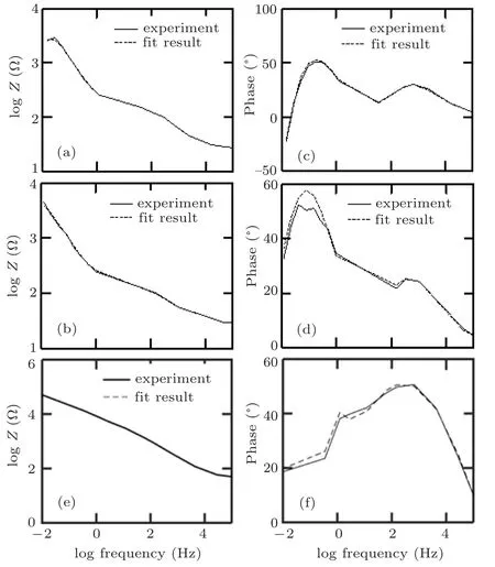
Fig.8. Bode (column I) and phase (column II) diagrams of all samples for experimental results (solid line) and simulation results (dashed line of(a)conventional multilayer thin film,(b)multilayer thin film with zigzag 1 structure,and(c)multilayer thin film with zigzag 2 structure.
Bode and phase plots obtained from experiments and simulations performed by equivalent circuits of different multilayer structures (conventional multilayer thin film, zigzag 1 structure,and zigzag 2 structure)are presented in Fig.8.These figures indicate the best fit between the experimental and simulation results.
Table 3 presents the equivalent circuit quantities obtained by using the simulations with ZView software. The data indicate that the zigzag structures(zigzag 1structure,and zigzag 2 structure)have smaller coating capacitance(Ccor)than the conventional multilayer thin film. The mentioned finding can be attributed to the smaller grains of zigzag structures than that of the multilayer structure due to the shadowing effect. Because the coating capacitance is a set of parallel capacitors,the total capacitance decreases as the number of parallel capacitors increases(decrease of the grain size and increase of the number of grain boundaries).
This table shows that the zigzag structures have high electrical resistances as compared with the conventional multilayer thin film due to the better nitride phase formation in these structures. The better formation of the nitride phase in the zigzag structures also eliminates the inductive behavior. The findings reveal that zigzag 2 structure has a smaller double layer capacitance (Cd) than zigzag 1 structure due to the geometry of the zigzag structure,since the capacitance decreases as the dielectric is tilted. The loss of induction behavior and the increase of electrical resistance with the decrease of the double layer and coatings capacitances in zigzag 2 structures increase the electrical impedance,and thus increasing the corrosion resistance of this structure.
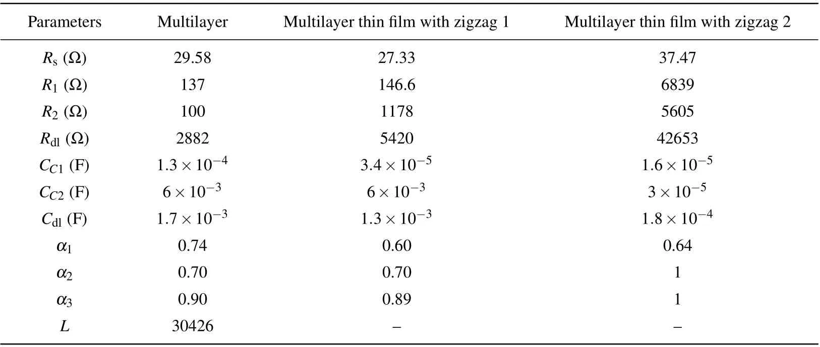
Table 3. Electrochemical parameters of AISI 304 stainless steel obtained from fitting of EIS spectra by equivalent circuit.
3.4. SEM results
To examine the surfaces of the samples after corrosion, SEM images of the conventional multilayer thin film and zigzag multilayer structures (zigzag 1 and zigzag 2 structures) are studied after corrosion test. These images are shown in Fig.8.Comparison of Fig.9(a) with Figs. 9(b) and 9(c), which show the SEM images of the conventional multilayer thin film and zigzag multilayer structures,respectively,reveal that the surface of the conventional multilayer thin film has a higher degradation than zigzag structures. Zigzag 1 structures have less degradation than the conventional multilayer structure. Moreover,zigzag 2 structure has a more suitable structure for protecting steel from corrosion.
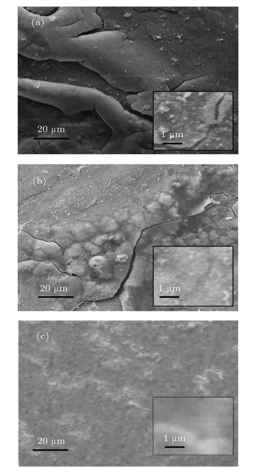
Fig.9. SEM micrograph of (a) conventional multilayer thin film, (b) multilayer thin film with zigzag 1 structure, and (c) multilayer thin film with zigzag 2 structure.
4. Conclusions
In the present study,conventional multilayer thin film and multilayer thin films including zigzag structures(zigzag 1 and zigzag 2 structures)are considered for the corrosion protection of AISI 304 stainless steel. Surface and crystalline studies of structures by using AFM and XRD reveal that although the zigzag structures have smaller grains than conventional multilayer structure due to the shadowing effect, nitride phase formation is better due to the porosity of these structures. The investigation of corrosion tests and SEM images indicate that multilayer thin films including zigzag structures have a lower corrosion rate,lower corrosion tendency,and higher corrosion resistance,and zigzag 2 structure has the best coating for corrosion protection in the samples. The equivalent circuit simulation by ZView software shows that the high corrosion resistance of zigzag 2 is attributed to the loss of inductance,the decrease of double layer capacitance, the decrease of coating capacitance,and the increase of the electrical resistance.
杂志排行
Chinese Physics B的其它文章
- Nonlocal advantage of quantum coherence in a dephasing channel with memory∗
- New DDSCR structure with high holding voltage for robust ESD applications∗
- Nonlinear photoncurrent in transition metal dichalcogenide with warping term under illuminating of light∗
- Modeling and analysis of car-following behavior considering backward-looking effect∗
- DFT study of solvation of Li+/Na+in fluoroethylene carbonate/vinylene carbonate/ethylene sulfite solvents for lithium/sodium-based battery∗
- Preparation of AlN film grown on sputter-deposited and annealed AlN buffer layer via HVPE∗
