Lagrangian analysis of the formation and mass transport of compressible vortex rings generated by a shock tube∗
2021-03-19HaiyanLin林海燕YangXiang向阳HongLiu刘洪andBinZhang张斌
Haiyan Lin(林海燕), Yang Xiang(向阳), Hong Liu(刘洪), and Bin Zhang(张斌)
School of Aeronautics and Astronautics,Shanghai Jiao Tong University,Shanghai 200240,China
Keywords: compressible vortex rings,Lagrangian coherent structure,mass transport
1. Introduction
Vortices play an important role to pulse jets and fuel injection in hypersonic engines. Understanding mass transport and dynamic genesis of those vortices is of particular importance to improve the mixing and combustion ability of engines. It should be pointed out that these vortices in hypersonic combustor are mostly compressible. Thus, this paper attempts to investigate one fundamental vortex in compressible flow,i.e.,the compressible vortex ring(CVR)to explain the mass transport and dynamic genesis of CVRs formation.
The most common equipment to generate a CVR in the laboratory is the shock tube. Adjusting the length or the pressure of the driver section can produce a wide range of incident shock Mach number(Ma)which induces different types of CVRs. CVRs generated at the open end of a shock tube were initially observed experimentally by Elder and Haas.[1]Using spark Schlieren photographs, they obtained the variation of translational velocity and diameter of the CVR as time and distance increasing for Ma=1.12 and Ma=1.32.Arakeri et al.[2]experimentally investigated the CVRs for Ma=1.1,1.2,and 1.3 using Particle Image Velocimetry(PIV).They indicated the translational velocity of the ring after pinch-off is about 0.7Ub, where Ubis the fluid velocity behind shock as it exits the tube. As Ma further increases, more complicated features of CVRs emerge. Phan and Stollery[3]first observed the rearward facing embedded shock in the axial region of the CVR for Ma=1.5 using schlieren photographs.Baird[4]showed more details of the embedded shock by using differential interferometry. Interestingly, Brouillette et al.[5]found that the minimum Ma for the presence of an embedded shock is 1.34 when the length of the driver section is larger than the critical length. Furthermore, Brouillette and Hebert[6]observed counter rotating vortex ring (CRVR)formed ahead of the leading CVR when Ma ≥1.6 with critical driver length. Using high-speed schlieren photography,Kontis et al.[7]observed multiple CRVRs ahead of the leading CVR at Ma=1.63. These investigations have provided rich information about the flow pattern and the formation of CVRs.However,the mass transport during the CVR formation is less studied.
As one most important mechanism,vortex pinch-off significantly affects the formation of vortex rings and plays a special role on mass transport and mixing of vortex rings. The relationship of pinch-off of a vortex ring to the dynamic properties of fluid has been studied a lot in incompressible vortex ring(ICVR). For ICVRs generated with a piston-cylinder apparatus,Gharib et al.[8]found that the leading vortex ring pinches off from the trailing jet when the formation time equals to approximately 4 which is termed as‘formation number’. When the stroke ratio (ratio of stroke length to nozzle exit diameter) is greater than formation number, the trailing vortices occur. Krueger and Gharib[9]further indicated that the vortex ring pinch-off represents a maximum of impulse with the same energy. Sau and Mahesh[10]found that ICVR with trailing column of fluid is less effective at mixing and entrainment than the isolated ICVR. Moreover, the rate of change of entrained fluid attains the maximum when pinch-off happens,which suggests an optimal mixing behavior when the ICVR pinches off. In spite of so many valuable results of pinchoff in ICVR, the study of pinch-off in CVR is rather limited.Arakeri et al.[2]and Murugan and Das[11]observed the pinchoff phenomenon of CVR in experiments. Pe˜na Fern´andez and Sesterhenn[12]found the CVR pinch-off takes place in a multiple way for large Reynolds numbers by using direct numerical simulations(DNS).There is no study focused on the changes of fluid dynamic and of the mass transport caused by pinchoff, and such changes could be critical to fluid mixing. That brings us to wonder the pinch-off and the mass transport of CVR.
In this paper, we attempt to use Lagrangian coherent structures(LCSs)to investigate the dynamic genesis of CVRs and understand the mass transport during the formation of CVRs. The development of LCSs can be divided into two stages. In the first stage,LCSs were identified from the ridges of finite-time Lyapunov exponent(FTLE)fields.[13]Many researches have demonstrated that the FTLE field for planar systems reveals coherent lines that behave as separations in a wide variety of applications. Yet, Haller and his coworkers found that the ridges of FTLE would create theoretical inconsistencies,as well as false positives and negatives in hyperbolic LCS identification. Most importantly, the ridges of FTLE could not detect the elliptic (vortex-type) and parabolic (jet-core type) LCSs. In 2010, the more reliable mathematical methods based on the geodesic theory was developed to identify the LCSs in flows.[14,15]This theory generalizes the concept of LCSs into hyperbolic,elliptic,and parabolic LCSs. Hyperbolic LCSs represent the material lines that locally exhibit the most repelling shrink lines or the most attracting stretch lines,which are referred to as repelling LCSs and attracting LCSs,respectively. Elliptic LCSs represent the shear lines in a velocity field and act as the boundary of coherent Lagrangian vortices. Compared with hyperbolic and elliptic LCSs representing the material surfaces with locally maximal properties,the parabolic LCSs are the material surfaces with exceptional global coherence properties. The framework of LCS has been used to study the ICVRs for some time.[16-18]In this paper,both FTLE field and elliptic LCS are used to show the mass transport and dynamic genesis of CVRs.
The rest of the paper is organized as follows. Section 2 describes the detail of numerical simulation and LCS calculation. Section 3 provides the formation process of the CVR and the identification of pinch-off. The mass transport of CVR is analyzed in Section 4. Finally the paper ends with a summary in Section 5.
2. Methods
2.1. Simulation details
We performed a three-dimensional (3D) numerical simulation using an in-house code by fortran. The threedimensional compressible Navier-Stokes equation in a finite volume formulation along with continuity, energy and state equations is solved. The fifth-order weighted essentially nonoscillatory (WENO) is adopted for spatial discretization and the third-order Runge-Kutta scheme is used for temporal advancement.

Fig.1. The slice of computation domain and the distribution of the grid in z=0 m plane.
The slice of z=0 m plane cut from the computational domain is shown in Fig.1. The shock tube is comprised by the length adjustable driver section and the driven section that has a constant length of 1200 mm. The inner diameter(Dtube)of the shock tube is 64 mm and the thickness of the tube wall is 4 mm. The shock tube exit is located at x=0 m plane.Initially, the temperature in the whole domain is 300 K and the pressure is 101325 Pa except the driver section. The pressure in the driver section is three times larger than it in the driven section and ambient area. The nonslip condition is applied at the inner and outer boundary of the shock tube. The boundaries of ambient area are set as pressure outlets. The grid inside the shock tube is equidistant in the radial direction(y direction) and stretching away from the shock tube exit in the axial direction(x direction). As for the grid in the ambient area,both radial and axial direction have been discretized using a grid stretching. The time when the shock arrives at the tube exit is taken as t =0 s. As for the CVR formation process,the most concerned domain is the ambient area confined by x=0 ~0.5 m and y=−0.15 ~0.15 m. In order to choose the most effective number of the grid,three sets of grid distribution in this area are shown in Table 1. The variation of the total circulation in this area is examined in Fig.2. The total circulation is calculated by integrating vorticity over the upper half of the concerned domain (y >0). The circulation of all three grids obtains a constant value. It can be noted that good agreement has been obtained and the discrepancy among the three sets of results is acceptable. Considering the simulation accuracy and the economy, all the results presented and analyzed in this paper are computed by using grid 2 with time step t=5×10⁻⁸.

Table 1. Details of the grid used for grid validation in the area confined by x=0 ~0.5 m and y=−0.15 ~0.15 m.
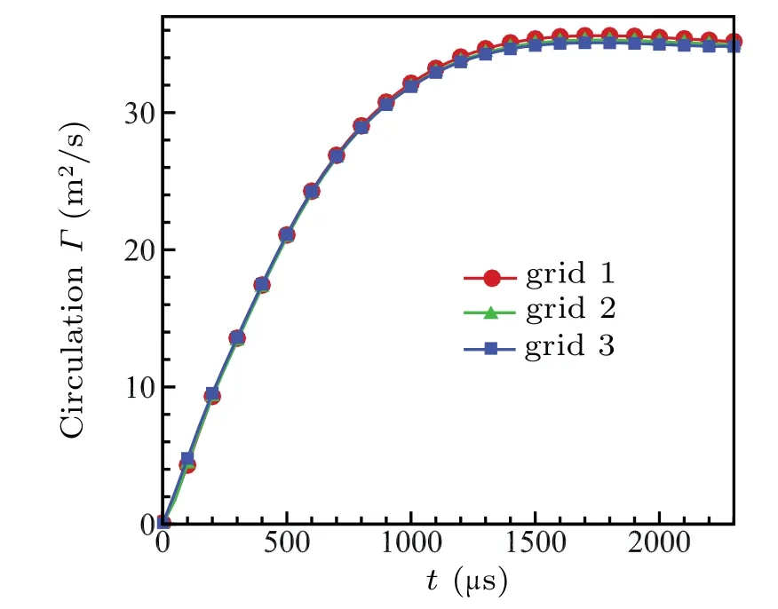
Fig.2. Comparison of the total circulation variation with time of the concerned domain for grid 1,grid 2,and grid 3.

Fig.3. Comparison of schlieren contours (∇ρ magnitude) between present result and Dora et al.[19] for PR=10 and DL=230 mm at t=480µs.
In order to verify the results of our simulation,two sets of initial flow condition according to Dora et al.[19]and Murugan et al.[20]are performed. The pressure ratio between the driver and driven section (PR) and the length of the driver section(DL)are the control parameters to generate different patterns of CVR. Figure 3 shows the schlieren contours (∇ρ magnitude) for PR=10 and DL=230 mm at t =480 µs. It can be seen that the detailed structures of the CVR have been calculated by our simulation and the comparison with Dora et al.[19]is well too. As for quantitative comparison,we compared the radial velocity(v,m/s)profile along the horizontal line across the vortex core to the numerical and experiment results in Murugan et al.[20]for PR=7 and DL=165 mm at t =560µs in Fig.4. Good agreement is obtained.
For the purpose of studying the mass transport of the CVR during formation, three cases with the same PR=3 are chosen.According to inviscid shock tube relation,PR=3 presents that the incident shock Mach(Ma)is 1.26. DL for cases 1,2,and 3 is 70 mm,100 mm,and 165 mm,respectively. Following Krueger and Gharib,[9]the Reynolds number is defined as Re=Γ/ν, where Γ is the circulation of the vortex ring as it has completely formed,and ν is the kinematic viscosity. The Reynolds number for each case is 8.4×10⁵, 12×105, and 19×105.
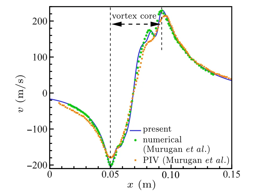
Fig.4. Comparison of the radial velocity (v) profile along the horizontal line across the vortex core between present result and Murugan et al.[20] for PR=7 and DL=165 mm at t=560µs.
2.2. Lagrangian coherent structures


Then defining the finite-time Cauchy-Green deformation tensor as

(where the superscript * denotes the transpose) allows us to compute FTLE as


λ-lines(r′(s))are obtained as closed trajectories of one of the two vector fields

where λ plays the role of a parameter. Any orbit of λ-lines turns out to stretch uniformly under the flow map and any subset of the line increases its arc length precisely by a factor of λ.Then, the outermost member of a closed family of λ-lines is called a coherent Lagrangian vortex boundary(elliptic LCSs).


The axisymmetric structure of CVRs has been observed by the experiments.[2,11]According to the fact that the vortex rings and its trailing jet keep axisymmetric for a long time,some simulation studies of CVRs are using the axisymmetric form of Navier-Stokes equation.[19,20]to reveal more details of the CVRs. In our study, we also observed the axisymmetric property of CVRs. Thus, in spite of the 3D simulation of CVRs in our studies, two-dimensional (2D) flow field is sufficient to reveal the evolution of CVRs. Therefore, the 2D LCS is used to the 2D symmetric plane which is the z=0 m plane. During the calculation of Cauchy-Green strain tensor,the value of|T|is of particular importance.According to Huhn et al.[27]and David et al.,[28]in order to get the clear FTLE ridges and the appropriate elliptic LCS, |T| should be large enough to insure that the neighboring initial particles achieve sufficient separation and be short enough to keep the computation from becoming overly complicated. In order to find the appropriate |T|, we calculated three sets of FTLE field with|T|=1.5×10⁻³s,|T|=2.0×10⁻³s,and|T|=2.5×10⁻³s and the results are shown in Fig.5.Both|T|=2.0×10⁻³s and|T|=2.5×10⁻³s yield visibly sharp ridges in the FTLE field.Considering the accuracy of calculation,|T|=2.5×10⁻³s is used in the following parts.

Fig.5. FTLE contours(normalized by the maximum)for case 3 at t=2300µs with three different values of|T|:(a)|T|=1.5×10⁻³ s,(b)|T|=2.0×10⁻³ s,and(c)|T|=2.5×10⁻³ s. The levels of forward FTLE increase from white to red. The levels of backward FTLE decrease from white to blue.
3. Results and discussion


Fig.6. Velocity profile(Ue)in the shock tube exit versus time(t)for three cases.
The trend is similar. While the shock wave leaves the exit and travels into the atmosphere,an expansion wave travels inside the tube,causing the velocity of the fluid at the tube exit increasing. The velocity increases to the peak then gradually decreases.Longer DL produces higher peak velocity and average velocity. The difference between the velocity at the shock tube exit generates different CVRs.
3.1. The formation process of the CVR
We describe the formation process of a CVR by presenting the vorticity and FTLE field in Fig.7. The shock leaves the shock tube exit and diffracts at t∗=0, causing the slipstream rolling up and the vortex core forming. In Fig.7(a),according to the vorticity contours,it can be observed that the vortex core is forming. In the FTLE field, ridge of forward FTLE(ridge-F)bounds the fluid that will be absorbed into the vortex ring eventually. Thus, the ridge-F in the shock tube represents the rear edge of the CVR. The ridge of backward FTLE (ridge-B) in the vortex core exhibits a spiral structure,denoting the mass transport barrier inside the core.At t∗=3.6(Fig.7(b)), the vortex core is larger than it at t∗=1.98. The rear edge denoted by ridge-F has came out of the tube. The ridge-B at x = 0.14 m defines the front edge of the vortex ring. The ridge-F and ridge-B can be superimposed to provide a closed region of the vortex ring. However the shape of the ring is odd. It contains part of the jet fluid, which means the vortex ring would absorb this part of fluid into itself at a later time. At t∗=4.47(Fig.7(c)),the trailing vortices appear due to Kelvin-Helmholtz instability on the jet front. From the FTLE,it can be confirmed that the first trailing vortex will be absorbed into the leading CVR.In Fig.7(d),the leading CVR has formed completely. It separates from the trailing jet and translates downstream with a nearly constant velocity.
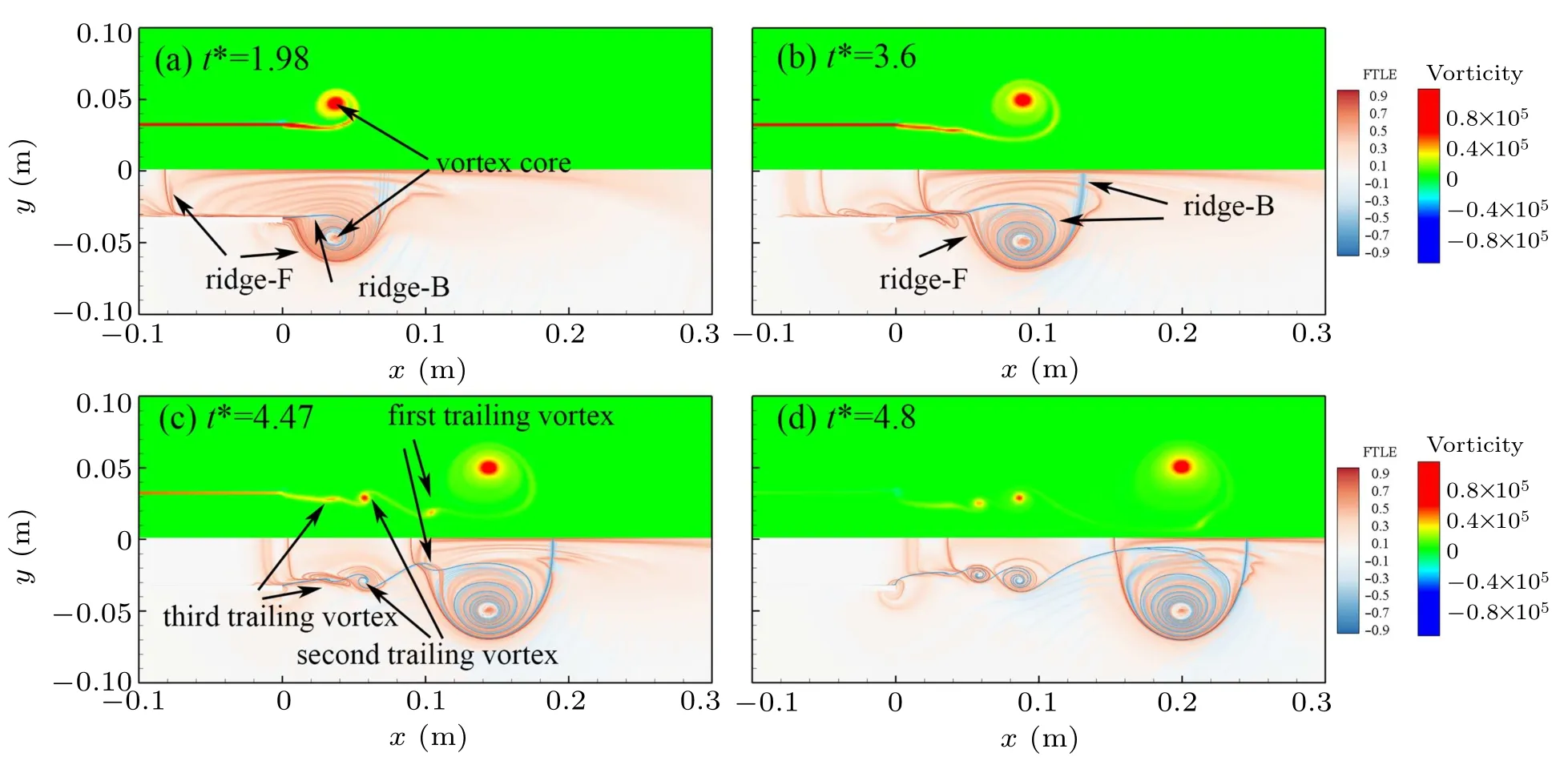
Fig.7. Vorticity contours(up half)and FTLE contours(down half)of vortex ring during evolution for case 3. The FTLE contours have been normalized by the maximum. In the FTLE field,the levels of forward FTLE increase from white to red,the levels of backward FTLE decrease from white to blue.
3.2. Pinch-off of CVRs
As mentioned in the introduction,Gharib et al.[8]discovered that incompressible vortex rings generated from the starting jets forming would pinch off from the generating jet when the piston stroke to diameter ratio(L/D)equals approximately 4,which also called formation number.The formation number(F∗)indicates the onset of the pinch-off process and coincides with the onset of trailing vortex rolling-up. To identify the formation number,Gharib et al.[8]termed it as the time when the circulation of the total jet is equal to the circulation of the leading vortex ring. The total circulation is calculated by integrating vorticity over the upper half of the concerned domain(y >0)because of the axisymmetric characteristic of CVR in the present study. As to the circulation of the leading vortex ring, the first step is to obtain the vortex ring region by forward and backward FTLE,then we integrate the vorticity over the domain encompassed by ridge-F and ridge-B. The nondimensional circulation (Γun) is normalized by the maximum flow velocity in the shock tube exit (Umax) and tube diameter(Dtube). The circulation variations with formation time for three cases are shown in Fig.8. The total circulation for the three cases bears a resemblance in tendency. It increases at first then attains a stable value. Longer DL generates higher circulation of leading CVR and higher constant circulation of the total jet. The dotted line indicates the formation number of each case. The sub-figures are extracted at the time when the circulation of total jet has become constant for each case. It is obvious that the trailing vortices exist in cases 2 and 3,which means the pinch-off has happened in the two cases. The formation number of cases 2 and 3 are 1.93 and 2.63.Case 1 only produces a leading CVR and it indicates the CVR is just pinchoff or non-pinch-off. Compared with the formation number of ICVRs, the formation number of CVRs is smaller and also does not exhibits a universal timescale. This may be caused by the background co-flow induced by the moving of the incident shock. At the investigation on the ICVRs generated by a starting jet, it has been found that the formation number of ICVRs will decrease as much as 1. Thus,how the background co-flow affects the formation number of CVRs needs further discussion in the future.
This may be caused by different mechanisms of generation of vortex rings. It needs further discussion in the future.
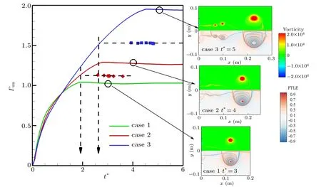
Fig.8. Circulation of total jet (solid lines) and leading vortex ring (symbols) as a function of formation time t∗. The diamonds denote the leading vortex ring in case 2;the squares denote case 3. Dotted lines are used to indicate the formation number of each case. Sub-figures are the vorticity contours(up half)and FTLE contours(down half)of the fluid field.
4. Mass transport of CVR
For a CVR generated at the open end of a shock tube,the dynamic genesis of CVR is referred to which portion of the fluid will end up in the ring and what ambient fluid is entrained in the ring,as well as how each part of fluid affects the CVR.Here we identify those fluid that is eventually advected as parts of the ring by elliptic LCSs and FTLE fields.
Elliptic LCSs have been shown to extract closed boundaries within which the fluid material remains as a coherent unit without any filamentation near the boundaries over a finite period of time.[28,29]We show the elliptic LCSs as solid black line associated with the FTLE field for the three cases in Fig.9. The time for each case is the same absolute time t =2250µs. Thus the formation time for each case is different. For all the cases,the CVRs at t=2250µs have separated from the trailing jet and translated for a period of time.The region encompassed by the elliptic LCS is becoming larger and larger as the DL increases. Also it can be noted that the elliptic LCS encompasses a significantly larger region than what could be defined as a vortex based on vorticity magnitude,but a relatively small region than what is confined by the combination of ridge-F and ridge-B.As we have known that the region enclosed by the combination ridge-F and ridge-B is the vortex area associated with the bulk fluid transport.[22]And the elliptic LCS is the objective definition of a vortex that encompasses a coherent unit. Here comes the question,what is the dynamic difference between the two regions and what roles they play on the formation process of CVRs.
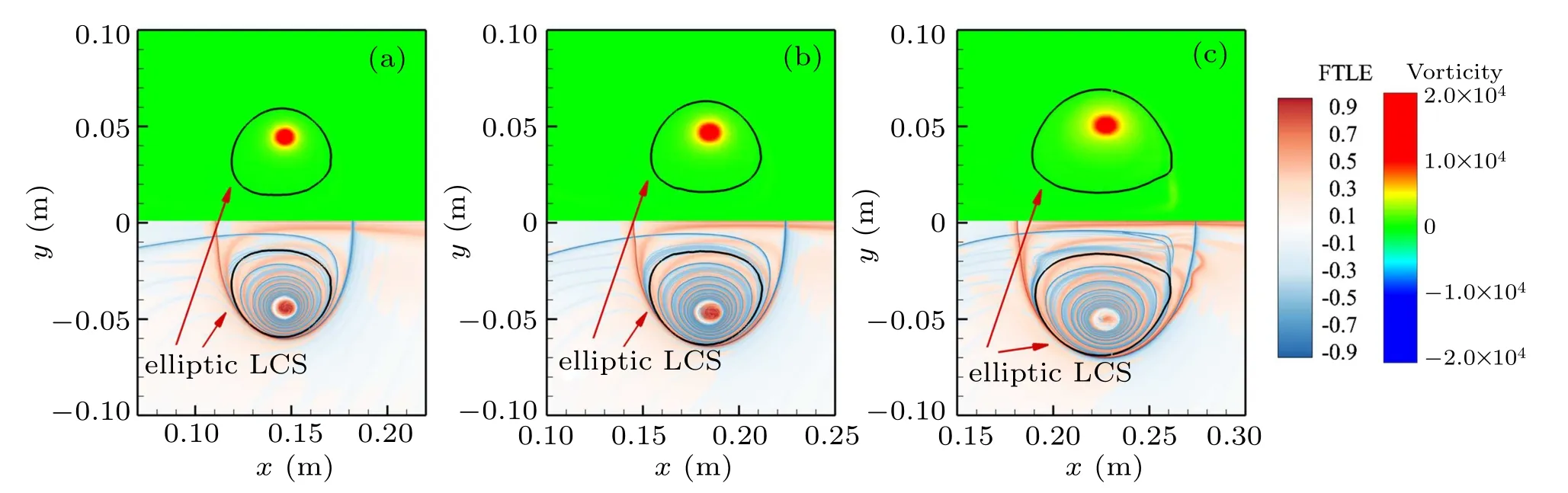
Fig.9. Vorticity contours (up half) and FTLE contours (down half) for three cases at their steady translational stage: (a) case 1 at t∗=3.7, (b) case 2 at t∗=4.24,and(c)case 3 at t∗=5.02. The FTLE contours have been normalized by the maximum. The levels of forward FTLE increase from white to red.The levels of backward FTLE decrease from white to blue. The black solid lines is the vortex boundaries identified by elliptic LCS.
4.1. The origin of advected bulk
In order to answer above questions,we construct some areas shown by dashed line with different colours according to elliptic LCS,ridge-F and ridge-B for the three cases as showed in Fig.10. In case 1 and case 2,there are three areas. Area 1 is confined by the elliptic LCS.Areas 2 and 3 are isolated by ridge-B inside the ring. The bottom edge of area 3 is the axis of symmetry(y=0 m). For case 3,except the three areas with similar shapes as in case 1 and case 2,area 4 is divided by two branches of ridge-B inside the ring as shown in the sub-figure extracted from Fig.10(c).
To begin with,we intend to investigate the origin and evolution of the fluid in these distinct areas. A parcel of fluid particles with diacritical colours are distributed in those areas.We advect particles from the time shown in Fig.10 for each case backward in time to t∗=0. The evolutions of trace particles for the three cases are shown in Figs.11-13,respectively.In Fig.11, all the particles stay in the region confined by the boundary defined by the combination of ridge-F and ridge-B during the evolution time. Area 2 gets significantly stretched and folded around area 1. From t∗=0 to t∗=3.7, the particles in area 2 advect anticlockwise around area 1. While area 3 stretches not as much as area 2. Particles in area 3 keep as a cluster and also move anticlockwise around area 1 as time increasing,but the trajectory of area 3 is much less than that of area 2. On the evolution process, fluid in area 3 mostly stays around the axis of symmetry. At t∗=2.9 and t∗=3.7, area 1 remains as an individual coherent units. At t∗=0 the location of particles of the three areas provides an estimate of fluid origin,which means these fluids would consist of the CVR.It also can be noted that the fluid encompassed by elliptic LCS attaches with the wall of the shock tube. The fluid forming area 3 is upstream of area 1 and restrained by the ridge-F at the rear edge. All the fluid in area 3 is from the shock tube,while areas 1 and 2 contain part of atmosphere fluid which would be entrained in the CVR.

Fig.10. Areas distinguished by elliptic LCS and the ridges of FTLE along with the FTLE contours(normalized by the maximum)for three cases at their steady translational stage: (a)case 1 at t∗=3.7,(b)case 2 at t∗=4.24,and(c)case 3 at t∗=5.02. The levels of forward FTLE increase from white to red.The levels of backward FTLE decrease from white to blue. Area 1 is defined by elliptic LCS.

Fig.11. Temporal evolution of the material inside the three areas of fluid identified in Fig.10(a)for case 1. The background is the FTLE field(normalized by the maximum)at the corresponding formation time. The formation time corresponding to each frame is indicated in top right. The evolution is from the largest formation time to 0. The red colour represents the tracers belonging to area 1;the blue represents to area 2;the green represents to area 3.

Fig.12. Temporal evolution of the material inside the three areas of fluid identified in Fig.10(b)for case 2. The background is the FTLE field(normalized by the maximum)at the corresponding formation time. The formation time corresponding to each frame is indicated in top right. The evolution is from largest formation time to 0. The red color represents the tracers belonging to area 1;the blue represents to area 2;the green represents to area 3.

Fig.13. Temporal evolution of the material inside the three areas of fluid identified in Fig.10(c)for case 3. The background is the FTLE field(normalized by the maximum)at the corresponding formation time. The formation time corresponding to each frame is indicated in top right. The evolution is from the largest formation time to 0. The red color represents the tracers belonging to area 1;the blue represents to area 2;the green represents to area 3.
The evolution of area 1 to area 3 for case 2 and case 3 is similar to case 1. In the evolution of particles in case 2(Fig.12),the main difference with case 1 is occurred at t∗=0.As DL increases from 70 mm to 100 mm,area 2 has a branch extending to the atmosphere. It means the entrained atmosphere fluid is more than in case 1. Also the fluid from the shock tube to form the CVR is more because the ridge-F in the rear edge is located at approximate x=−0.11 m compared with x=0.09 m in case 1.
While for case 3,except for the longer brunch of area 2 at t∗=0 and the more tube fluid to be ended up in the CVR compared with cases 1 and 2,the particular part is area 4(Fig.13).The fluid in area 4 stems from some fluid near the wall of the shock tube. At t∗=4.12,from the FTLE field,it can be concluded that area 4 is a trailing vortex and will be merged by the leading CVR in the later time. But this trailing vortex will not affect the coherent units confined by the elliptic LCS.
In summary, we have identified the material bulk of the fluid which gets transported away from the tube exit as the region of the vortex ring. Area 1 contains the most part of the tube fluid that attaches to the tube wall and the atmosphere fluid near the shock tube exit. It translates as a whole unit without much filamentation near the boundary. Area 2 is a portion whose advection is mostly induced by area 1. And area 3 where all the fluid comes from the tube would acts as the center of the ring.
4.2. The role of advected bulk
In order to understand the role of each area on the formation of CVRs, We calculated the evolution of mass and non-dimensional circulation associated with the region that occupied by tracer particles of each area. The mass and nondimensional circulation at a given time are numerically estimated by binning an area that encompasses all the tracer particles associated with an area,and then identifying those bins that contain at least one tracer particle. The method is also applied by David et al.[28]and they show the error of less than 2%. In Fig.14,we plot the evolution of non-dimensional circulation as well as the mass of each area for the three cases.In Figs. 14(a), 14(c), and 14(e), it can be seen that mass is approximately conserved in three areas for each case. It verifies the accuracy of the tracer particles’transportation. Area 1 contains approximately 60%of the total mass of the whole advected bulk. In Figs.14(b),14(d),and 14(f),it can be noted that area 1 acquires the most part of the circulation during the whole time and reaches the nearly constant value at a later time. The circulation of area 1 begins with an increase to its peak, then a slight drop follows. Areas 2 and 3 in all three cases occupy little circulation. As for area 4 in case 3,it carries non-negligible circulation at the early time, then drop to nearly zero at the later time. Consequently, it seems that the elliptic LCS is more effective than ridges of FTLE in capturing the circulation area.

Fig.14. Temporal evolution of mass and the non-dimensional circulation(Γun)associated with each of the three areas of fluid identified in Fig.10 for the three cases. The mass variations are in panels(a), (c), and(e); the nondimensional circulation variations are in panels(b),(d),and(f).
Thus, it can be concluded that area 1, more specifically the area confined by elliptic LCS, is the most important part of the CVR.It contains the vast majority of circulation of the ring. Thus area 1 can be called as vortex part of the CVR.Area 2 contains most part of atmosphere that is entrained into the vortex ring but would not be absorbed into the vortex part.Thus, area 2 can be identified as entrainment part of CVRs.Area 3 is all from the tube but occupying no circulation,it can be called the advected part of the CVR.
It has been known that the pinch-off process involves the separation of distinct vorticity-carrying regions of the flow(i.e., the vortex ring and trailing jet, respectively).[30]Since area 1 in all three cases carries the majority of vorticity, we compare the variation of circulation of area 1 with the three cases in Fig.15. The black lines denote the formation number obtained by circulation method in Section 3.It can be seen that the formation number corresponds to the time when the circulation of area 1 attains constant. Thus, the elliptic LCS provides a simple criterion to estimate the formation number of CVR.This convenient method of determining pinch-off would be instructive to the investigation of entrainment and mixing of CVR which need further study.

Fig.15. Circulation of area 1 as a function of formation time t∗. The circles denote the area in case 1;the squares denote case 2;the triangles denote case 3. Solid lines are used to indicate the formation number of each case.
5. Conclusion
In this paper, we calculated three CVRs generated by shock tubes using simulation methods. In order to analyze the mass transport and dynamic genesis of CVRs,FTLE,and elliptic LCSs are used.
The study investigates the formation process of CVRs by FTLE and the mass transport is more clearly seen than through the vorticity field. Unlike the ICVRs, the formation number of CVRs for the three CVRs is not universal. As the DL increasing, the formation number is increasing. The CVRs can be divided into three parts by elliptic LCSs and ridges of FTLE.Fluid particles are distributed among the three parts at the time when the CVRs have separated from the trailing jet, then traced back to t =0 to identify the kinetic genesis of CVRs. The region encompassed by the elliptic LCSs is shown to objectively identify the ring that contains the most part of the circulation and approximately 60% mass. And the regions encompassed by the ridges of FTLE are shown to identify the material bulk of the fluid that gets advected away from the shock tube. According to the kinetic genesis of the three parts, the CVRs can be divided as vortex part which contains the most part of circulation of the ring,entrainment part which most consists of entrained atmosphere and advected part where all the fluid comes from the tube. More interestingly,the starting of pinch-off of the vortex part is corresponding to that of the CVRs. The elliptic LCSs provide a simple criterion to estimate the formation number of CVRs.
Acknowledgment
Besides, the authors would like to thank the Center for High Performance Computing of SJTU for providing the super computer π to support this research.
猜你喜欢
杂志排行

Chinese Physics B的其它文章
- Nonlocal advantage of quantum coherence in a dephasing channel with memory∗
- New DDSCR structure with high holding voltage for robust ESD applications∗
- Nonlinear photoncurrent in transition metal dichalcogenide with warping term under illuminating of light∗
- Modeling and analysis of car-following behavior considering backward-looking effect∗
- DFT study of solvation of Li+/Na+in fluoroethylene carbonate/vinylene carbonate/ethylene sulfite solvents for lithium/sodium-based battery∗
- Multi-layer structures including zigzag sculptured thin films for corrosion protection of AISI 304 stainless steel∗