Development of a 100 MPa water-gas two-phase fluid pressurization device
2021-03-03ShengbinLiHepingLiLinChenHongbinZhou
Shengbin Li •Heping Li•Lin Chen•Hongbin Zhou
Abstract This paper introduces a 100 MPa water gas twophase fluid pressurization device.The device can provide 100 MPa gas pressure and 200 MPa liquid pressure for small volume(<20 mL)high-pressure experimental devices.This device can make the pressure control independent of the temperature control without changing the material components of the system.The resolution of this device in adjusting the pressure is±0.2 MPa in the process of boosting and depressurizing.This pressure boosting device generates very little vibration during work and it can be used in experiments with strict requirements on vibration.As a thermodynamic parameter,pressure has a great influence on matter.In the field of experimental geochemistry,pressure is not only an experimental method and an extreme condition but an important physical parameter independent of temperature and chemical composition.
Keywords High-precision pressurization device·High pressure fluid·Gas pressurization·Liquid pressurization
1 Introduction
Temperature and pressure are two important intensive variables that describe the geochemical processes and they are also the two most important parameters in experimental geochemical research(Zeng 2003).Under high pressure conditions,the distance between the reactant particles is closer,which can reduce the reaction temperature,increase the reaction rate and the rate of product formation and shorten the reaction time(Liu and Qian 2012).For example,a small change in pressure under supercritical conditions will lead to large changes in the density and dielectric constant of aqueous solution(Johnson and Norton 1991).The reaction rate of water–rock interaction mainly depends on the density and dielectric constant of water(Zhang et al.2007),so the change of pressure will lead to the change of reaction rate of water–rock interaction(Zhang et al.2009).Near the critical point,density is very sensitive to the change of pressure(Johnson and Norton 1991).At the same time,density is closely related to the solubility of water.Therefore,pressure is an important physical parameter affecting the solubility of water(Xie 1997).
The phase separation caused by the pressure change of supercritical geological fluid plays an important role in the precipitation mechanism of ore-forming elements.In the study of migration,enrichment and precipitation mechanism of ore-forming elements,the process of cooling and decompression is involved(Pokrovski et al.2002,2005;Williams-Jones and Heinrich 2005).For example,when the temperature and pressure drop into the subcritical state,the gas–liquid separation process and metal redistribution in the gas–liquid phase occur in the supercritical fluid-containing metal(Zhang et al.2006a,b,2008).The gas-phase dissolution and migration of metals will lead to the formation of metal ores in the upper and peripheral areas of the deposit(Zhang et al.2006b).To carry out fine experimental research on this phenomenon,it is necessary to finely regulate the pressure in the pressure reduction stage.
In a small volume(<20 mL)hydrothermal autoclave,it is more difficult to generate high pressure than high temperature and it is also difficult to adjust the pressure precisely.Water(including aqueous solution)or gas is often used as the working medium in a hydrothermal experimental device.When conducting experiments in water or aqueous solution system,there are two main methods of generating fluid pressure:the thermal pressure method and the method of generating high pressure using high-pressure machinery(Zeng 2003).The thermal pressure method is a simple method for generating fluid pressure.The principle is that the fluid is thermally expanded in a closed system to increase the system pressure.The pressure depends on the temperature and the filling factor.In the high-pressure hydrothermal experiment,if water is used as the pressure medium when the pressure transmission medium is in the vapor–liquid coexistence stage,the pressure in the sample chamber is strictly equal to the saturated vapor pressure of water and the pressure in the sample chamber cannot be independent of temperature perform an in situ adjustment.When the medium is in a single-phase state(such as gas,liquid or supercritical state)and if it is necessary to adjust the confining pressure in the sample chamber independently of the temperature in situ,it can only be pumped into a fresh solution or discharged into the sample chamber.The interacting water fluid changed the material composition of the water fluid system artificially at this time.To generate high pressure,booster pumps were used to generate and transport high-pressure liquids or gases.An inert gas such as argon is pumped into the pressure vessel by the pressure pump so that the pressure can be adjusted independently of the temperature without changing the material composition of the system.Therefore,various types of pumps are basic equipment(pressure source)used in high-pressure laboratories.
To obtain the response mechanism of rock and mineral properties to pressure,it is necessary to accurately control the pressure in the high-temperature pressure vessel.If we want to accurately regulate the pressure of a pressure vessel with a small volume,including pressure control during the pressure increase and decrease,a single input or output fluid flow is required to be small.Otherwise,the pressure of the pressure vessel will increase by tens of atmospheres to hundreds of atmospheres instantaneously,negating the purpose of precise pressure control.
However,existing high-pressure fluid pressure devices have the following problems:
1.One stroke displacement of high-pressure liquid booster pump(200 MPa)and high-pressure gas booster pump(100 MPa)is too large.For example,one stroke displacement of a super-small displacement high-pressure liquid booster pump is greater than 0.4 mL,one stroke displacement of an ultra-small displacement gas booster pump is greater than 19.7 mL.For a pressure vessel with a volume of only a few milliliters to tens of milliliters,it cannot meet the requirements of precise pressurization and decompression.
2.The displacement of an ultra-low displacement highpressure axial piston pump is 1 mL/r,the rated working pressure is 25 MPa,the rated speed is 3000 r/min(Qian et al.2018).The high-pressure micro-flow electroosmotic pump can only reach the flow rate of nanoliter to microliter per minute under the output pressure of 0–40 MPa(Chen 2003).The output pressure of 40 MPa and the flow rate below 2μL/min can only be obtained by the high-pressure microflow constant flow pump(Wan 2012).None of the above three ultra-low displacement high-pressure pumps can be used for experimental research at depths below 1.5 km.
3.Generally,the reciprocating booster pump needs to use a one-way valve.Because the mechanical structure of the one-way valve determines that the minimum single pass volume of the one-way valve is generally large and the one-way valve has microleakage,the leakage volume is in the order of 10–1μL/min,so it is difficult to accurately transport the flow of microliter and sub—μL/min to meet the requirements of accurate pressure control(Chen and Guan 2003).Because of the existence of a one-way valve,the booster pump can not be used for depressurization control.
4.At present,most of the liquid and gas pressure reduction schemes used are mostly to open the pressure relief valve directly for pressure relief or to reduce the pressure through the pressure relief valve,but the mechanical structure characteristics of the pressure relief valve determine its control pressure.The accuracy is very poor.At present,there is no pressure relief valve with a pressure regulation resolution of±0.1 MPa when the pressure range is 0–100 MPa and the flow rate is very small.
5.Under certain experimental conditions,there are strict requirements for vibration.For example,precision optical systems used in conjunction with high-temperature and high-pressure experimental devices have strict requirements for the vibration of the instrument and the environment to measure the optical focus and spectrum well.The high-pressure liquid booster pump and high-pressure gas booster pump are generally airdriven booster pumps.The power of the air-driven booster pump comes from compressed air and compressed air requires an air compressor.The vibration and noise of general air compressors are very big,even the use of silent air compressors can not meet the strict vibration requirements.
6.The pressure of most high-pressure hydrothermal experiments cannot be adjusted independently of temperature and the pressure is equal to the saturated vapor pressure of the aqueous solution at a certain temperature.Therefore,these experiments have the following problems:①it is difficult to distinguish the trend and degree of the influence of temperature and pressure as independent variables;②it is impossible to carry out experimental research on the system with pressure higher than saturated vapor pressure,such as geological phenomena with abnormal fluid pressure.
To solve the above problems,this paper introduces a high-precision water gas two-phase fluid pressurization device.The pressure boosting device can provide 100 MPa gas pressure and 200 MPa liquid pressure.This device can also adjust the pressure independently of the temperature without changing the composition of the substance in the pressure vessel.The resolution of this device to adjust the pressure is±0.2 MPa in the process of boosting and depressurizing.
2 Experimental apparatus
Figure 1 is the mechanical schematic diagram of the pressure generator.This set of fluid pressurization device includes a gas pressurization pipeline and liquid pressurization pipeline.In the gas boosting part,the hydraulic pump driven by the hydraulic station compresses the gas in the cylinder to 35 MPa,which is stored in a mediumpressure gas storage tank.The pressure vessel is connected with a pressure reducing valve in a medium pressure gas storage tank.Two manually operated piston screw gas pumps are connected between the pressure reducing valve and the pressure vessel.The gas pump is designed for any application where gas is to be compressed within a small volume to develop pressure.The structural diagram of the manually operated piston screw gas pump is shown in Fig.2.The photos of the gas boosting pipeline are shown in Figs.3 and 4.The piston rod and body of the gas pump are made of 316 L and the rated working pressure is 100 MPa.The gas is released through the pressure reducing valve into two gas pumps.A handwheel of counterclockwise rotating pumps drives the piston back.When the pistons of two gas pumps reach the final limit,close the valve B between the reducing valve and the pumps and then rotate the handwheel of the gas pumps clockwise to push the piston forward for pressurization.Finally,the gas pressure can be increased to 100 MPa and the pressure can be reduced by rotating the handwheel of the gas pumps counterclockwise.

Fig.1 Mechanical schematic diagram of the pressure generator.1.Controller;2.Hydraulic station;3.Hydraulic pump;4.Medium-pressure gas storage tank;5.Electric contact pressure gauge;6.Pressure relief valve;7.Valve A;8.Pressure reducing valve;9.Valve B;10,11.Manually operated piston screw gas pumps;12.Pressure relief valve;13.Valve C;14.Remote controller;15.Pressure sensor A;16.High-pressure vessel;17.Valve D;18.Liquid pressure generator;19.Pressure sensor B;20.Valve E;21.Reservoir

Fig.2 The structural diagram of the manually operated piston screw gas pump.1.Screw;2.Nut;3.Handle collar;4.Handle;5.Bearing;6.Piston rod;7/9.Bracket;8.Polypak seal;10.Body

Fig.3 Device diagram of medium and low pressure pipeline of gas booster pipeline
Because the compressibility of liquid is very small,the control of liquid pressure needs to be more precise,that is,the volume of single output liquid needs to be as small as possible.In the liquid pressurized part,the liquid pressure generator(Figs.5,6)is a manually operated piston screw liquid pump.It is designed for any application where a liquid is to be compressed within a small volume to develop pressure.A reservoir is shown connected using valves and fittings to the pressure vessel that is to be pressurized.The pressure sensor B has been included for determining pressure.With valve D closed and valve E open,the handle of the pressure generator is rotated counter-clockwise to draw fluid from the reservoir into the cylinder body of the pressure generator.Valve E is then closed and valve D is opened.By rotating the pressure generator handle clockwise,the piston will now compress the fluid to develop pressure in the component that is to be pressurized.If sufficient pressure is not reached in one stroke,the system can be recycled.Valve D can be closed to maintain pressure in the components.Valve E is then opened and fluid is again drawn into the pressure generator from the reservoir.Closing Valve E and opening Valve D will now allow the pressure generator to be operated to develop increased pressure in the component.Pressure in the component can be vented by opening both valves.Valve A,B,C,D and E are needle valves.Tubing is cold drawn,seamless and in the 1/8 hard condition(not annealed).Tensile strength is approximately 40 percent higher than that of annealed tubing.The valve body and tubing are made of 316 L and the rated working pressure is 200 MPa.

Fig.4 Device diagram of high-pressure pipeline of gas booster pipeline
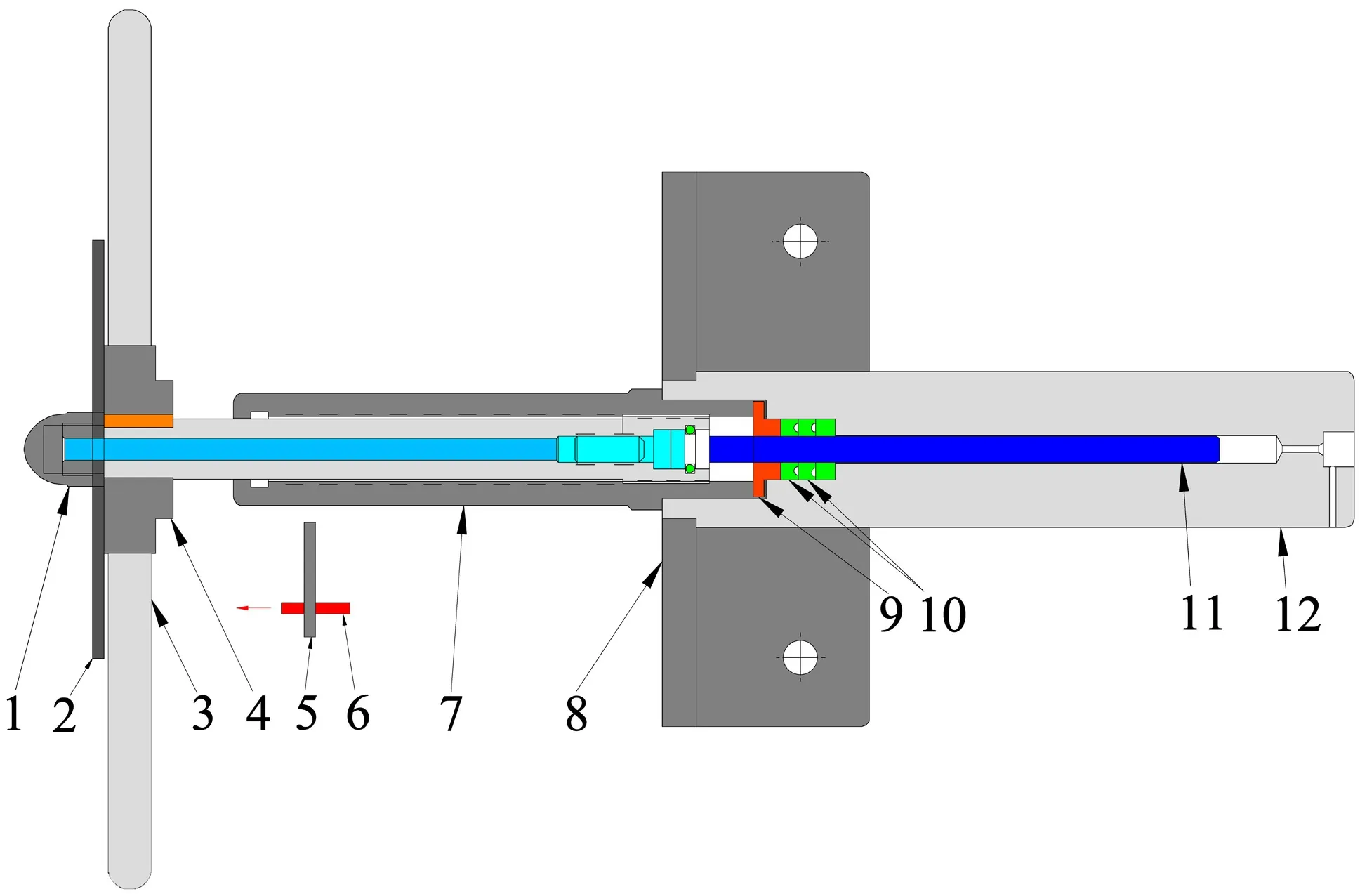
Fig.5 The structural diagram of the manually operated piston screw liquid pump.1.Handle nut;2.Dial;3.Handle;4.Handle collar;5.Fixed bracket;6.Micro laser;7.Nut;8.Bracket;9.Top packing washer;10.Polypak seal;11.Shaft;12.Body

Fig.6 Device diagram of a manually operated piston screw liquid pump
The shaft and body of the manually operated piston screw liquid pump are made of 316 L and the rated working pressure is 200 MPa.It is designed for any application where a liquid is to be compressed within a small volume to develop pressure.The high-pressure generator is easily mounted to a workbench and maximum pressures may be obtained with a minimum amount of effort by the operator.To improve the accuracy of manual pressure control,a circular dial is installed at the rotating handle of the liquid supercharger,as shown in Figs.5 and 6.The center of the dial coincides with the axis of the piston rod.Install a micro laser on the fixed bracket.The optical path of the laser is perpendicular to the scale on the dial.The laser spot diameter is 0.5 mm,which has good collimation and high indication accuracy.The fluid volume can be easily calculated by the rotation angle of the dial and the spot position of the laser.For example,the known volume of the liquid booster cylinder is 12 mL,the stroke length is 6 inches and the plunger advances 1 inch every 14 turns of the handle.When the handle is rotated for one circle,the volume of pumped fluid is 0.14 mL and the handle is rotated for 1° and the volume of pumped fluid is 0.40μL.This single minimum output is far less than the general reciprocating booster pump’s single stroke output.Moreover,there is no one-way valve used here,so the pressure in the pressure vessel can be reduced by turning the handle of the supercharger anticlockwise.The accuracy of the step-down is the same as that of step-up.
All pressure sensors and gauges in this device have been verified by the Shenzhen Academy of Metrology and Quality Inspection and National Hi-tech Metrology Station.The verification regulation of the pressure sensors is JJG882-2004‘‘Pressure Transmitter’’.The certificate number is 174,316,477.The verification accuracy is 0.1 %F.S.The measuring range of pressure sensor B is 200 MPa.The pressure sensor is connected to the paperless recorder.The brand of the paperless recorder is Pangu,the model is VX6306R/U and the measurement accuracy is less than 0.2% F.S.
3 Operation process
1.Before the experiment,the liquid driven gas booster pump is pushed to pressurize the gas through the hydraulic station to generate a medium-pressure source,which is stored in the medium-pressure gas storage tank.When the pressure reaches 35 MPa,the electric contact pressure gauge feeds back the signal to the controller and the booster pump stops working.
2.0.1–35 MPa test:Compress all the piston rods of the two manually operated piston screw gas pumps.Close the pressure relief valves and valve E,open the valve A,B and C.Turn the pressure reducing valve clockwise to increase the pressure and turn the pressure reducing valve counterclockwise to decrease the pressure.By adjusting the opening of pressure reducing valve,the speed of pressure rise and decrease can be adjusted.The smaller the opening of pressure reducing valve,the higher the resolution of pressure regulation.When the pressure reaches 35 MPa,the pressure can also be reduced by adjusting the gas pumps.The first pump can reduce the pressure from 35 to 10 MPa and the second pump can reduce the pressure from 10 to 5.3 MPa.
3.Based on the 0.1–35 MPa experiment,the screws of the manually operated piston screw gas pumps are all turned back,the high-pressure valve A,B,E and the pressure reducing valve is closed.Turn the handle of the gas boosters clockwise to increase the pressure and turn the handle of the gas boosters counterclockwise to decrease the pressure.The higher the pressure,the smaller the angle of each rotation of the handle when adjusting the same pressure.When the predetermined pressure is reached,the pressure is maintained.If the pressure fluctuates during the pressure maintaining process,the pressure can be maintained stable by fine adjustment of the manual high-pressure gas boosters.
4.There are two methods for adjusting pressure independently of temperature in a water or aqueous solution system.One method is to pump inert gas(such as argon)into the pressure vessel with the gas pressure part of the experimental device so that the pressure in the pressure vessel is greater than the saturated vapor pressure of water.The pressure in the pressure vessel is equal to the saturated vapor pressure of water plus the partial pressure of inert gas.Another method is to adjust the pressure by compressing the volume of liquid.
5.The system pressure can be reduced to normal pressure by opening the pressure relief valve after the experiment.
4 Test instrument
We designed a device(Fig.7)for measuring the resolution of fluid pressure regulation.This device is mainly composed of a frame,hydraulic cylinder,piston rod,force sensor and other parts.The hydraulic interface of the hydraulic cylinder is connected to the water–gas two-phase fluid boosting device and the pressurizing medium is pumped into the cavity of the hydraulic cylinder through the water–gas two-phase fluid boosting device.A rubber Oring seals the piston rod and the hydraulic cylinder.The piston rod is made of tungsten carbide with an outer diameter ofmm and surface roughness of Ra 0.8.The force sensor is fixed on the frame and is used to measure the force received by the piston rod.The range of the force sensor is 20 kN and the measurement accuracy after calibration is 0.5% F.S.The force received by the piston rod is equal to the fluid pressure times the crosssectional area of the piston rod.The fluid pressure is increased at 0.1 MPa intervals and the measured value of the force sensor is recorded.Since the minimum effective measurement value of the force sensor is 2% F.S.(JJG 144-2007),the data with the force sensor value greater than 400 N shall be processed.The relationship between the force of the piston rod and liquid pressure is shown in Fig.8.Linearly fitting the force of the piston rod to the pressure of the liquid,we get R2=0.99991,the slope is 112.69801 and the slope represents the cross-sectional area of the piston rod.The calculated radius of the piston rod cross-section is 5.99 mm and the deviation from the actual piston rod radius of 6.00 mm is 0.1%.The fluid pressure can be adjusted at intervals of 0.1 MPa.The measurement accuracy of the fluid is guaranteed by the calibrated pressure sensor B.Based on the above tests,it can be considered that the resolution of the pressure adjustment of this water–gas two-phase fluid boosting device is better than±0.2 MPa.

Fig.7 Schematic diagram of the force measuring device of the hydraulic cylinder piston rod.1.Frame;2.Hydraulic cylinder;3.Hydraulic interface;4.Hydraulic chamber;5.Piston rod;6.Seal ring;7.Force sensor

Fig.8 Diagram of the relationship between the force on the piston rod of the hydraulic cylinder and the fluid pressure
This device can be applied to the pressurization of pressure vessels with small volume,high resolution of pressure regulation,small vibration in the process of experiment and can increase the pressure in the pressure vessel under the condition of constant temperature and no change of material composition in the pressure vessel.The main principle is to reduce the flow rate per stroke.Reducing the flow per stroke is to use the small lead screw to drive the plunger booster pump.The screw driving the plunger can make the minimum stroke of the plunger very small,so the flow per stroke of the supercharging device is very small.This is different from the principle of Pascal,which is used in the general reciprocating pressure pump.The flow rate per stroke of the booster pump using the Pascal principle is too large to meet the requirements of fine pressure regulation of small volume pressure vessels.
The vibration produced by this device is very small during the experiment,which can meet the vibration requirements of most spectroscopic laboratories.The main reasons are:1.there is no air compressor in this supercharging device;2.before the experiment,the liquid driven gas pump can be used to compress the gas in the cylinder to 35 MPa and store it in the medium pressure gas storage tank;3.during the experiment,only the piston screw liquid pump and the piston screw gas pump need to be adjusted manually;4.this set of pressurization device is mainly used for pressurizing small volume pressure vessels,so continuous pressure supplement is not required in the experimental process.
5 Conclusion
This article introduces a high-precision water gas twophase fluid pressure boosting device.This set of supercharging device is suitable for providing fluid pressurization for small volume(<20 mL)pressure vessel,which can provide 100 MPa gas pressure and 200 MPa liquid pressure.The resolution of this device to adjust the pressure is±0.2 MPa in the process of boosting and depressurizing.This device can also adjust the pressure independently of the temperature without changing the composition of the substance in the pressure vessel.
AcknowledgementsThis study was financially supported by the National Key R&D Program of China(2016YFC0600104),the Strategic Priority Research Program(B)of the Chinese Academy of Sciences(XDB 18010401),the National Natural Science Foundation of China(41902043),the Science and Technology Foundation Project in Guizhou Province([2019]1316,[2020]1Z032).
杂志排行
Acta Geochimica的其它文章
- Early Silurian Wuchuan-Sihui-Shaoguan exhalative sedimentary pyrite belt,South China:constraints from zircon dating for K-bentonite of the giant Dajiangping deposit
- Niobium-tantalum oxide minerals in alluvial placer deposits from the Ngoura area,East-Cameroon
- Helium and argon isotope geochemistry of the Tibetan Qulong porphyry Cu-Mo deposit,China
- Translocation and distribution of mercury in biomasses from subtropical forest ecosystems:evidence from stable mercury isotopes
- Neoproterozoic highly fractionated I-type granitoids of Shillong Plateau,Meghalaya,Northeast India:geochemical constraints on their petrogenesis
- Coprecipitation of metal ions into calcite:an estimation of partition coefficients based on field investigation