Bandwidth-enhanced dual-polarized antenna with improvedbroadband integrated balun and distributed parasitic element
2021-01-12FuSuidaoCaoZhenxinGaoDiChenPengXuChangzhi
Fu Suidao Cao Zhenxin Gao Di Chen Peng Xu Changzhi
(School of Information Science and Engineering, Southeast University, Nanjing 210096, China)
Abstract:A bandwidth-enhanced dual-polarized antenna is proposed for 2/3/4/5G applications, which is composed of distributed parasitic elements (DPEs), a main radiator, two improved broadband integrated baluns and a reflector. First, a novel tooth-shape shorted slot line in the improved broadband integrated balun is analyzed to adjust the input impedance of the antenna. Then, DPEs with 2×2 circular plates loading over the main radiator are proposed to improve broadband impedance matching and radiation pattern. By utilizing impedance compensation of the tooth-shaped shorted slot line and the electromagnetic induction of the DPEs, the antenna achieves an enhanced impedance bandwidth and a stable radiation pattern. To verify these ideas, the bandwidth-enhanced dual-polarized antenna was fabricated and measured. The experimental results indicate that the proposed antenna achieves an operating bandwidth of 72.2% (1.69 to 3.60 GHz) with a return loss (RL) less than -15 dB and a port-to-port isolation (ISO) larger than 30 dB. The antenna obtains a half-power beamwidth (HPBW) within (66±5)° and a gain within (9.0±0.6) dBi in the 2/3/4G bands, and an HPBW within (61.5±2.5)° and a gain within (9.8±0.3) dBi in the 5G band. Across the whole band, the cross-polarization discrimination (XPD) and the front-to-back ratio are both larger than 20 dB.
Key words:dual-polarized antenna; bandwidth enhancement; integrated balun; distributed parasitic elements; impedance matching
Broadband dual-polarized antennas operating for 1.71 to 2.69 GHz have been widely used in 2/3/4G base stations[1-8]. Recently, the Ministry of Industry and Information Technology (MIIT) of China awarded the 3.5 to 3.6 GHz and 3.4 to 3.5 GHz bands to China Unicom and China Telecom for 5G commercial trial operations. In fact, the three major operators in South Korea have officially provided 5G commercial services for the 3.5 GHz band in December, 2018. However, the construction of 5G networks is a complex process since it involves many factors such as technology, capital and commerce. The traditional 2/3/4G will be used as a supplement to coexist with 5G for a long time. Therefore, it is valuable to develop a bandwidth-enhanced dual-polarized antenna with an operating bandwidth covering 1.71 to 3.6 GHz for 2/3/4/5G systems.
Dual-polarized antennas for base station applications are generally classified into cross-electric dipole antenna and cross-magnetoelectric dipole antenna. The cross-electric dipole antenna, which contains two pairs of orthogonal electric dipoles, is excited by baluns[2-3,6], coaxial cable[1,4,9]or coupling[5,10-11]. Usually, cross-electric dipole antennas have an impedance bandwidth of 45% to 55%[1-6,11-13]. Recently, researchers have utilized a variety of methods to realize the bandwidth enhancement for cross-electric dipole antennas. In 2018, Cui et al.[14]proposed a cross-electric dipole dual-polarized antenna with a 67% (1.39 to 2.8 GHz) impedance bandwidth for return loss (RL) less than -15 dB. It utilized U-shaped slots etched on the four-leaf clover radiator and a multi-layer metal patch introduced above the radiator. In Ref.[15], with a spline-edged bowtie radiator and tapered transmission lines, an antenna is proposed to obtain a bandwidth of 68% (1.427 to 2.9 GHz) with a VSWR less than 1.5 and port-to-port isolation (ISO) larger than 20 dB. These methods either increase the complexity of the antenna structure or reduce ISO. The cross-magnetoelectric dipole antenna was proposed by Wu et al.[16], which uses two pairs of equivalent electric dipoles composed of four magnetic dipoles to generate dual-polarized radiation waves. The cross-magnetoelectric dipole antenna has a more stable combined pattern generated by magnetic current and electric current[7-8,16-17]. By utilizing complex impedance matching networks, 69.5% bandwidth (1.5 to 3.1 GHz) for RL less then -10 dB is achieved in Ref.[18]. In 2018, Lu et al.[19]proposed a cross-magnetoelectric dipole antenna with a bandwidth of 82.5% (1.58 to 3.83 GHz) for the voltage standing wave ratio less than 1.5 by using Γ-shaped feeding strips. However, the unstable radiation pattern and rectangular box-shaped reflector limit the applications of the antenna. Compared with the cross-magnetoelectric dipole antenna, the cross-electric dipole antenna can obtain a better overall performance without a large-size cavity reflector or a complex impedance matching network.
In this paper, a bandwidth-enhanced dual-polarized antenna based on the cross-electric dipole antenna is proposed for 2/3/4/5G applications. This antenna operates in the band from 1.71 to 3.6 GHz with a size of 62 mm×62 mm×51 mm (without a plate reflector). An improved broadband integrated balun with a tooth-shaped shorted slot line is analyzed to explain the mechanism of the broadband impedance transformation for cross-electric dipole antennas by changing the high-frequency current phase. A distributed parasitic elements (DPEs) loading over the main radiator is proposed to improve both broadband impedance matching and radiation pattern for the dual-polarized antenna.
1 Operating Principle
1.1 Antenna structure
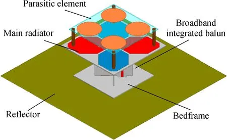
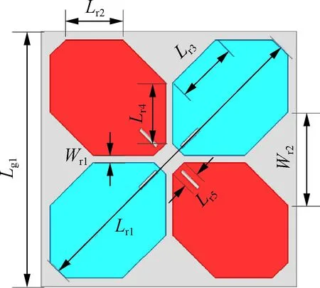
As shown in Fig.1, the bandwidth-enhanced dual-polarized antenna consists of DPEs, a main radiator, improved broadband integrates baluns, a bedframe and a reflector. All substrates are TLT-8 produced by Taconic Corporation, with a relative dielectric constantεrof 2.55 and a thicknesstof 0.762 mm. The main radiator is fixed on the bedframe by the perpendicularly crossed broadband integrated baluns, and the bedframe is placed on the plate reflector. The DPEs are supported by four plastic posts above the main radiator. The main radiator shown in Fig.2(a) consists of two pairs of orthogonal cross-electric dipoles with the red one for +45° polarization and the blue one for -45° polarization. The arm of the crossed dipole is designed to be a hexagonal. The DPEs shown in Fig.2(b) is composed of 2×2 circular elements printed on the upper surface of the substrate, with each cell being loaded above each dipole arm.
(a)

(b)Fig.1 Configuration of the bandwidth-enhanced dual-polarized antenna. (a) Oblique view; (b) Side view
(a)
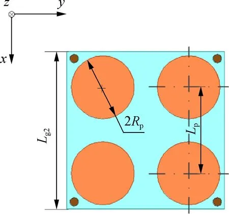
(b)Fig.2 Configuration of radiators. (a) Main radiator; (b) DPEs
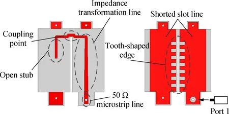
The configuration of the improved broadband integrated baluns is shown in Fig.3. The balun is composed of a Г-shaped microstrip line printed on the front side of the substrate and a shorted slot line on the back side. The microstrip line consists of a 50 Ω microstrip line connected to a coaxial cable, an impedance transformation line and an open stub. The assembly method of the integrated baluns is similar to Ref.[20]. The -45° polarization is excited by port 1 and the +45° polarization is excited by port 2. Due to the symmetry of the geometry, only port 1 is analyzed below. The proposed antenna is simulated and optimized by Ansoft HFSS 15, and the geometric parameters are listed in Tab.1.
(a)

(b)Fig.3 Configuration of the improved broadband integrated baluns. (a) +45° polarization; (b) -45° polarization

Tab.1 Parameters of the bandwidth-enhanced dual-polarized antenna mm
1.2 Improved broadband integrated balun
The improved broadband integrated balun was first proposed in Ref.[21] to realize the broadband balanced feed for the dual-polarized notched-band antenna. The mechanism of impedance matching for the improved broadband integrated baluns will be explained in detail here.
The equivalent circuit of integrated balun shown in Fig.4 can be used to analyze the bandwidth enhancement of the input impedance. The energy is coupled to the slot line by the microstrip line and excites the cross-electric dipole. The dipole is directly connected in parallel to the slot line, since the coupling point between the microstrip line and slot line is close to the dipole. The input impedance of the cross-electric dipoles placed on the ground is denoted byZd, which consists of the self-impedance of the dipole, the mutual impedance between the cross-electric dipoles, and the mutual impedance between the mirror dipoles generated by the ground. In practical application,Zdis usually obtained by electromagnetic simulation. The input impedance looking into the shorted slot line at the coupling pointZccan be calculated by the transmission line impedance equation as whereZs,lsandβsare the characteristic impedance, length and phase constant of the slot line, respectively.
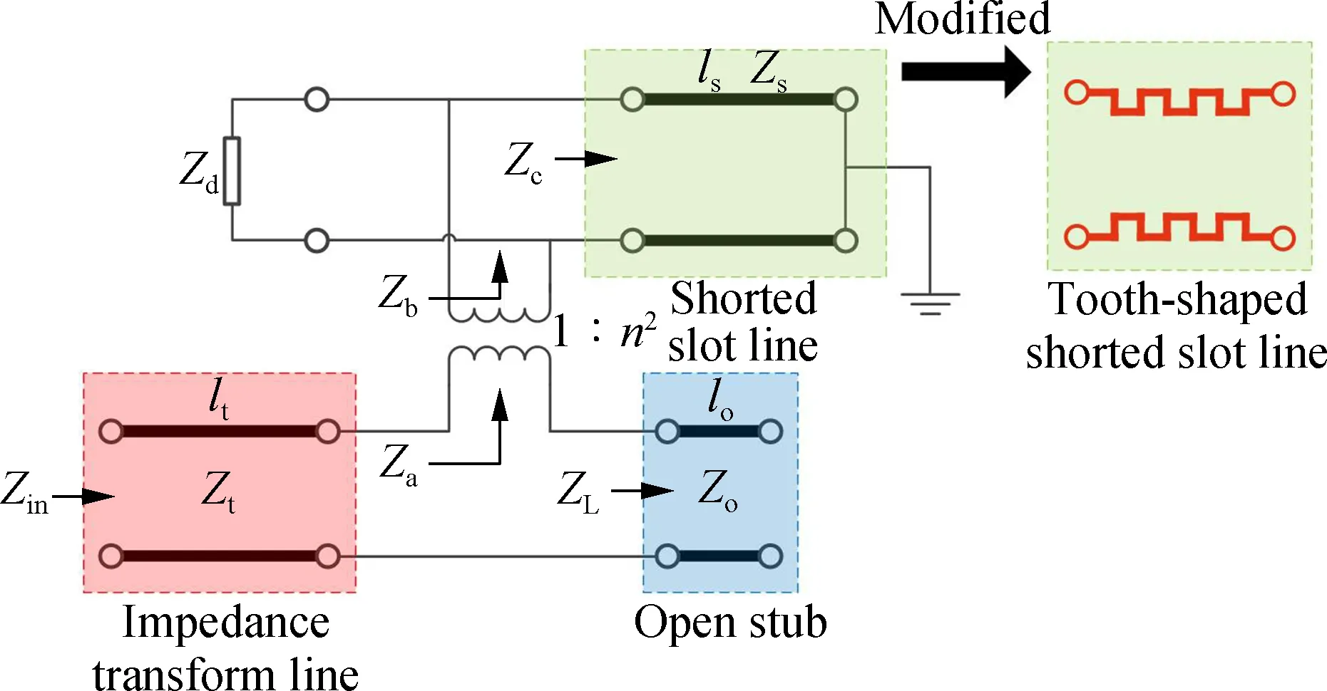
Fig.4 The equivalent circuit of the broadband integrated balun with a tooth-shaped shorted slot line
(1)
The coupling between the slot line and microstrip line can be regarded as an ideal transformer with a turn ratio ofn[22].Zbis obtained by connectingZdandZcin parallel,and the input impedanceZacan be obtained byZbas wheren2is called the impedance transformer coefficient and can be obtained by the ratio of the input impedance excited by the voltage source at the coupling point in the microstrip line and the input impedance excited by the voltage source at coupling point in the slot line.
(2)
Za=n2Zb
(3)
The input impedanceZLof the open stub is
ZL=-jZocotβmlo
(4)
whereZoandloare the characteristic impedance and length of the open stub, respectively;βmis the phase constant of the microstrip line;Zais connected in series with the open stub; and the input impedanceZincan be calculated as
(5)
whereZtandltare the characteristic impedance and length of the impedance transformer line, respectively. At low frequencyf0, whenβsls=βmlt=π/2,Zincan be simplified as
(6)
Therefore, the broadband integrated balun can improve the impedance matching of the cross-electric dipole antenna by open stub and slot coupling. At high frequency 2f0, ifβmlt=π andβsls≠π are satisfied,Zincan be expressed as
(7)
At this time, the input impedanceZinof the cross-electric dipole antenna can be compensated for by adjusting the input impedanceZcof the slot line.
The improved broadband integrated balun with the tooth-shaped shorted slot line is proposed for improving impedance matching at a high frequency. The tooth-shaped shorted slot line can increase the high-frequency electrical length (βsls) of the slot line by etching a tooth-shaped structure, and causeβsls≠π to be established at a high frequency. Then, the input impedance of the cross-electric dipoles can be compensated for by the shorted slot line according to Eq.(7). The input impedanceZinof the antenna with/without a tooth-shaped shorted slot line is given in Fig.5. It can be found that as the tooth-shaped shorted slot line is introduced, the resonant points remain almost the same at a lower frequency while shifting from 3.80 to 3.65 GHz at a higher frequency. Meanwhile, the real and imaginary parts ofZinapproach 50 Ω and 0 Ω around the high-frequency resonant point, respectively.
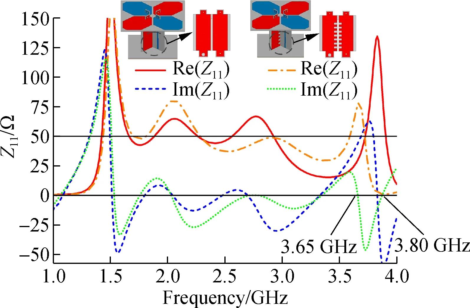
Fig.5 The input impedance of the antenna without/with tooth-shaped shorted slot line on the broadband integrated balun
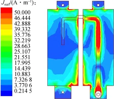
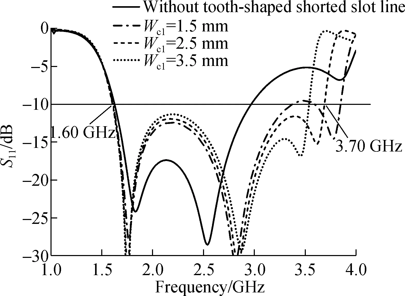
For a better understanding of the mechanism of the tooth-shaped shorted slot line, the current distribution on the balun at 3.65 GHz is shown in Fig.6. It is observed that as the tooth-shaped shorted slot line is introduced, the current density on the integrated balun is weaker. This is because the tooth-shaped shorted slot line is a two-wire transmission line with a reactive element periodically loading, which renders the attenuation constantαof the slot line equal to 0. In this case, the wave is attenuated along the slot line and cannot propagate. Meanwhile, the tooth-shaped shorted slot line improves the high-frequency impedance matching due to the compensation of the impedance of the cross-electric dipoles. The electric length of the low-frequency current does not change significantly due to no change in the overall length of the slot line. Fig.7 shows the effect of the depthWc1and widthWs1of the tooth-shaped shorted slot line on the impedance matching. AsWc1increases, the electrical length of the slot line at the high frequency increases and the high-frequency resonant point moves toward the lower frequency. By adjustingWs1, the input impedance of the shorted slot lineZccan be changed, and the impedance matching of the antenna can be improved around 3.65 GHz. When the optimal valueWc1= 2.5 mm,Ws1= 13 mm, the antenna achieves an impedance bandwidth of 79% (1.6 to 3.7 GHz) for RL less than -10 dB. Therefore, the improved broadband integrated balun achieves enhanced bandwidth impedance matching for the cross-electric dipole antenna.
(a)

(b)Fig.6 The current distribution on the integrated balun at 3.65 GHz. (a) Without tooth-shaped shorted slot line; (b) With tooth-shaped shorted slot line
(a)

(b)Fig.7 The effect of parameters of the tooth-shaped shorted slot line on impedance matching. (a) Wc1; (b) Ws1
1.3 Distributed parasitic element
The radiation pattern of the electric dipole placed horizontally on the ideal infinite conductor plane is
(8)
whereHis the distance from the dipole to the conductor plane;lis the half length of the dipole; andk= 2π/λis the propagation constant in the free space. According to Eq.(8), as frequency increases, the radiation pattern will deteriorate in the boresight direction (θ=0°), including the gain decreasing and the HPBW increasing. For a high-performance dual-polarized base station antenna, the RL is required to be less than -15 dB to reduce the energy reflection, and the HPBW is required to be stabilized around 65° to ensure the uniform coverage of the signal.
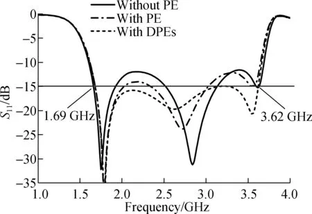
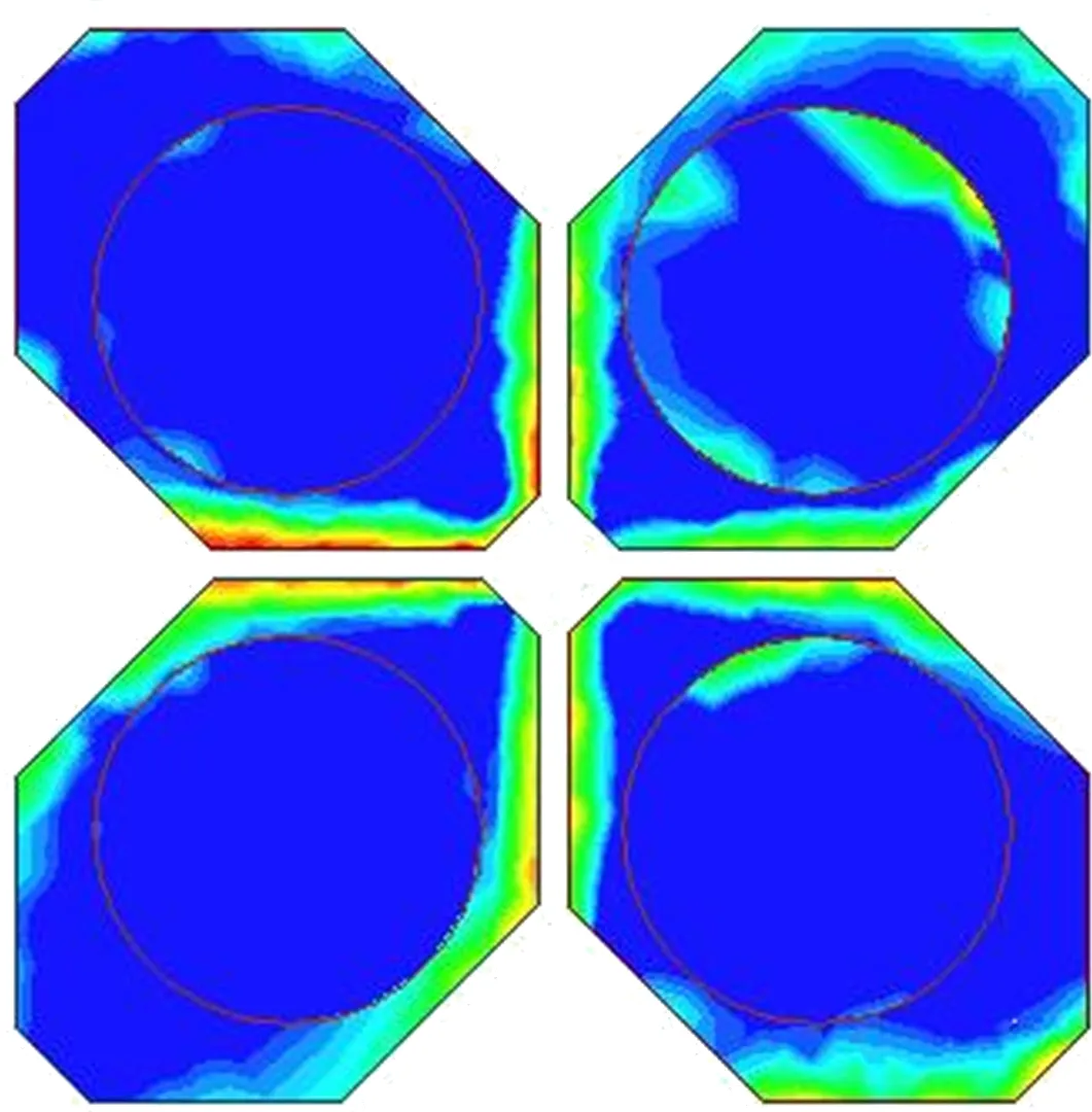
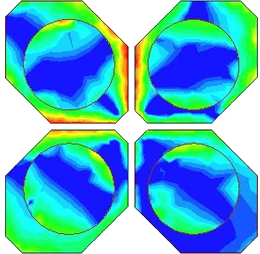
The parasitic element (PE) is a specially designed metal plate loaded around the radiator and it utilizes the electromagnetic induction in the near field to change the impedance matching or radiation characteristics of the antenna[2,9,14]. A DPE composed of 2×2 circular plates is proposed to realize the broadband impedance matching from 1.7 to 3.6 GHz and a stable radiation pattern from 2.8 to 3.6 GHz. The impedance matching of the antenna is shown in Fig.8(a), including the one without PE, the one with a PE of a single circular plate (radius is 14 mm and height is 18 mm), and the one with DPEs. As the PE is introduced, impedance matching of the antenna improves about 2.2 GHz, while no change is observed around 3.5 GHz. As the DPEs are introduced, the impedance matching is improved with a RL less than -15 dB across the whole band. The gain and HPBW of the radiation in theH-plane (zoy-plane) are shown in Fig.8(b). As indicated in Eq.(8), the gain and HPBW of the antenna without PE deteriorate at a higher frequency, which is due to the cancellation of the reflected wave from the plate reflector. The HPBW is narrowed and the gain is enhanced when the PE is introduced. The DPE has a greater stabilizing effect on the radiation pattern compared to the PE. The electric energy density of the antenna with/without DPEs at 2.2 and 3.5 GHz are simulated to analyze the principle of the DPEs in Fig.9. By introducing the DPEs, the current intensity between the adjacent dipole arms is reduced to be 2.2 GHz, which means that the DPEs change the low-frequency input impedance of the antenna. At 3.5 GHz, not only the current intensity is reduced, but also a stronger current is induced on the DPEs when the DPEs are loaded. This means that DPEs change the high- frequency input impedance and radiation pattern of the antenna simultaneously. The single cell of the DPEs improves the impedance matching and narrows HPBW at a higher frequency. The whole DPEs improve the impedance matching at a lower frequency, and it does not affect the radiation pattern due to the discontinuity between the elements. Therefore, the DPEs improve the whole-band impedance matching and stabilize the high-frequency radiation pattern simultaneously.
(a)

(b)
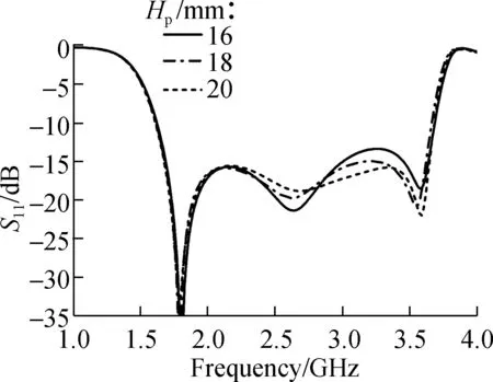
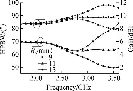
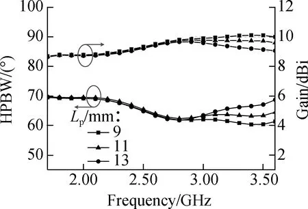
The effect ofRp,LpandHpon the impedance matching and radiation pattern are illustrated in Fig.10 and Fig.11, respectively. The radiusRpsignificantly affects the impedance matching and radiation. AsRpincreases, the impedance matching is improved at 3.5 GHz and deteriorated at 2.7 GHz, while HPBW and gain are reduced and increased at 3.5 GHz, respectively. The simulation results indicate that the single element is both a reactance element to improve the high-frequency impedance matching and a director element to stabilize the high-frequency radiation pattern. The optimal valueRp=11 mm. As lengthLpincreases, the impedance matching begins at 2.2 GHz, and the radiation pattern is stable at 3.5 GHz. This shows that the whole DPEs have an effect on input impedance at a low frequency and at radiation around 3.5 GHz.Lpis chosen to be 15 mm. The heightHpinfluences the impedance matching and the radiation pattern at a higher band from 2.7 to 3.6 GHz. The height can be used as a fine-tuning means of impedance matching, and the antenna achieves an optimal performance asHp=18 mm. The simulation results indicate that the bandwidth-enhanced dual-polarized antenna has a bandwidth covering 1.7 to 3.65 GHz, a (66±4)° HPBW and a (9.3±0.5) dBi gain.

(a)
(b)

(c)
(d)

(a)

(b)
(c)
(a)
(b)

(c)
2 Experimental Results
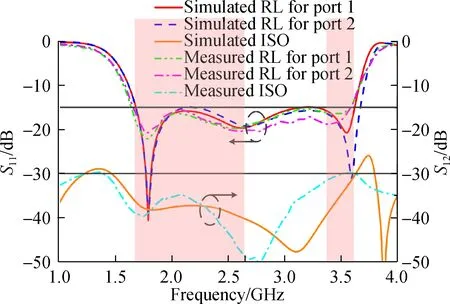
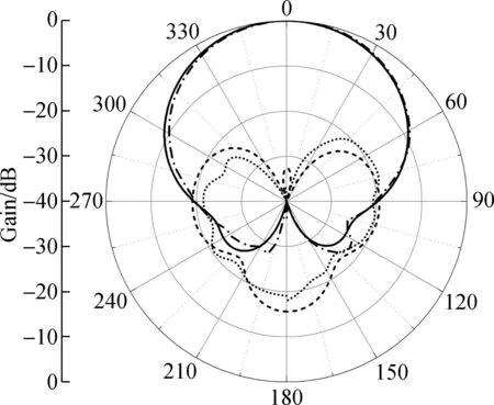
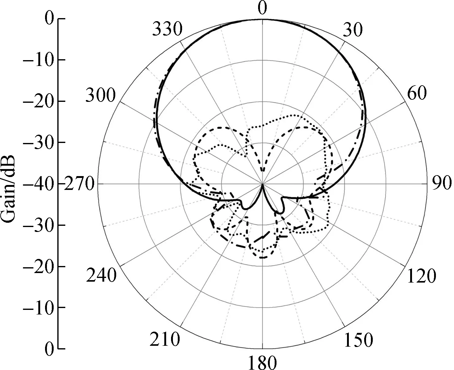
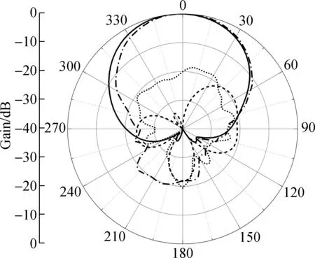
The prototype of the bandwidth-enhanced dual-polarized antenna for 2/3/4/5G applications is fabricated in Fig.12. The red shaded parts indicate 2/3/4G bands and the 5G band. The RL and ISO of the experiment and simulation for two ports are illustrated in Fig.13(a), and a good agreement is observed. The proposed dual-polarized antenna achieves an impedance bandwidth of 72.2% (1.69 to 3.60 GHz) for RL less than -15 dB and ISO larger than 30 dB. The measured gain and HPBW in the horizontal plane for ±45° polarization is illustrated in Fig.13(b) with the simulation results. It found that the measured and simulation results are in good agreement. The measured HPBW is less than the simulation value at the high frequency due to the error of DPEs assembly and test environment. As the high-frequency loss of the antenna and coaxial cable increases, the measured gain decreases and approaches the simulation value. The measured gain is within (9.2±0.9) dBi and the HPBW is within (64.5±6.5)° in 1.7 to 3.6 GHz. In the 2/3/4G bands, the antenna achieves a stable radiation pattern with an HPBW within (66±5)° and a gain within (9.0±0.6) dBi. In the 5G band, the antenna achieves an HPBW within (61.5±2.5)° and a gain within (9.8±0.3) dBi. The measured and simulation radiation patterns at 1.7, 2.7, 3.4 and 3.6 GHz in the horizontal plane for +45° polarization are shown in Fig.14. The back lobe of the measured co-polarization is larger than that of the simulation due to the reflection caused by the DPEs with a higher height and the effect of the testing environment. The cross-polarization discrimination (XPD) is larger than 20 dB in the boresight direction and the front-to-back ratio is larger than 20 dB.
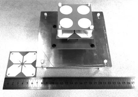
Fig.12 The prototype of the bandwidth-enhanced dual-polarized antenna
(a)
(a)
(b)
(c)

(d)
Tab.2 shows the comparisons between other bandwidth-enhanced dual-polarized antennas. The proposed antenna has an excellent comprehensive performance, including a wider bandwidth, higher ISO and a more stable radiation pattern.

Tab.2 Comparisons of bandwidth-enhanced dual-polarized antenna
3 Conclusions
1) The bandwidth-enhanced dual-polarized antenna with an improved broadband integrated balun is proposed for 2/3/4/5G applications. The proposed antenna can be integrated into the 2/3/4G outdoor base station, which can further support 5G signal coverage without increasing the antenna size.
2) To achieve enhanced bandwidth impedance matching, the tooth-shaped shorted slot line is used to change the electric length of the shorted slot line and to compensate for the high-frequency impedance of the cross-electric dipole antenna.
3) To further improve the whole-band impedance matching and stabilize the high-frequency radiation pattern, the DPEs is proposed. The single cell of the DPEs acts as a reactance element loading to improve the high-frequency impedance matching and to act as a director element to narrow the high-frequency beamwidth. The whole of the DPEs acts as a reactance element loading to improve the low-frequency impedance matching.
4) The proposed dual-polarized antenna is fabricated and obtained an impedance bandwidth of 72.2% from 1.69 to 3.60 GHz with RL<-15 dB and ISO>30 dB. At 1.71 to 2.69 GHz, the antenna achieves a stable radiation pattern with an HPBW within (66±5)° and gain within (9.0±0.6) dBi. At 3.4-3.6 GHz, the antenna achieves an HPBW within (61.5±2.5)° and gain within (9.8±0.3) dBi. In the whole band, the XPD is larger than 20 dB and the front-to-back ratio is larger than 20 dB. The bandwidth-enhanced dual-polarized antenna achieves a high performance for the application of the base stations.
杂志排行
Journal of Southeast University(English Edition)的其它文章
- Mechanism of coconut husk activated carbon modified by Mn(NO3)2
- Gorenstein dimensions for weak Hopf-Galois extensions
- Research on replacement depth of black cotton soil based on cracking behavior of embankment
- Pricing decision of green supply chain under the game competition of duopolistic retailers
- Design of cost allocation rule for joint replenishment with controllable lead time
- Effect improvement of drug pricing reform based on multi-channel coordination
