A Warming Structure for Piezoelectric Stack Working in Cryogenic Temperature
2020-11-25,,,,*
,,,,*
1.State Key Laboratory of Mechanics and Control of Mechanical Structures,Nanjing University of Aeronautics and Astronautics,Nanjing 210016,P.R.China;2.Beijing Institute of Space Long March Vehicle,Beijing 100076,P.R.China
(Received 17 March 2020;revised 20 April 2020;accepted 8 May 2020)
Abstract:It is widely acknowledged that the performance of a piezoelectric stack would decline with the temperature decreasing,which will exert negative influence on its application in low-temperature environment.Therefore,a convenient and efficient warming structure for the piezoelectric stack is proposed in this paper to solve this problem.Based on the theoretical analysis of heat transfer,two heating modes,namely,overall heating and local heating are analyzed and compared.Moreover,experimental tests are conducted to evaluate the effectiveness of the structure.Based on the results,it can be concluded that the theoretical results are confirmed with experimental results.Besides,the temperature and performance of the piezoelectric stack are kept stable as temperature varies from 10℃to-70℃,which manifests the feasibility of the structure.Therefore,this paper could be an available reference for those engaged in cryogenic investigation of smart materials and structures.
Key words:warming structure;piezoelectric stack;cryogenic temperature;heat transfer
0 Introduction
Piezoelectric stack actuators have superior electromechanical coupling characteristics,fast response and large output force[1-4],and thus they are widely employed in precise actuation,micro-positioning systems,active vibration control of the sting used in wind tunnel,vibration isolation system of helicopter and non-destructive evaluation,etc[5-9].In recent years,piezoelectric stacks have been extensively used in extreme environments such as high temperature,vacuum and radiation,of which cryogenic temperature applications are the most exemplified cases[10].For example,the piezoelectric stack is put to use for the purpose of active vibration control of the cantilever sting in the cryogenic wind tunnel[11-13],where the ambient temperature would drop to-150℃.It is worth mentioning that the temperature drop will directly affect the properties,output characteristics and driving load capability of a piezoelectric stack,resulting in the degradation of working efficiency[14-16].This phenomenon results from piezoelectric ceramic material composition,dopants,grain size and internal defects,and is dependent on the change of temperature[17].Hence,as for applications in low temperature environment,feasible warm-maintaining measures are required to keep the temperature at room temperature to ensure the working performance of the stack.On the other hand,piezoelectric stacks generate heat after running for a long time under high frequencies or high electric field magnitudes[18].Up to now,the majority of the current research lays emphasis on the design and testing of the heat dissipation structures for the piezoelectric transformers,but the heating and insulation structures for the piezoelectric stacks have been rarely studied.Rivers et al.conducted a preliminary study in the cryogenic wind tunnel,but the internal heating of the piezoelectric device turned out to be unsuccessful,and thus they designed and applied a new heating system for the recent low temperature tests.Their results indicated that the damper piezoelectric elements were kept at room temperature when the out temperature was-150℃[19].However,there is a lack of details or working principles about the heating system.For the purpose of ensuring the normal performance of the piezoelectric stack in cryogenic environment,it is highly significant and necessary to keep the piezoelectric stack working at appropriate temperature.
In this paper,a simple and effective insulation structure is presented on the basis of theoretical analysis and experiments.In accordance with the theoretical analysis of the axial heat conduction of the piezoelectric stack,the temperature distributions of the stack in the axial direction under two different heating modes-overall heating and local heating are compared.Furthermore,experimental tests are carried out under local heating conditions to evaluate the thermal insulation effect of the structure.
1 Structural Design and Theoretical Analysis
1.1 Structural design
According to previous study,it can only be heated and insulated in the radial direction of the piezoelectric stack for the reason that the two ends of the stack are directly installed to the mechanical structure to transfer the force.The schematic of the heating and insulation structure is shown in Fig.1.As can be seen,the heating film is attached to the outer surface of the piezoelectric stack with the packaging housing,and then the outside of the heating film is wrapped with the heat insulation materials.Moreover,the entire structure is installed in the mechanical structure,which is exposed to cryogenic environment.

Fig.1 Schematic diagram of the heating and insulation structure
1.2 Theoretical analysis
Energy generated by the heating film leads to a rise in the temperature of the stack,and since the insulating effect merely exists in the radial direction,energy is mainly transferred in the axial direction.According to the heat transfer theory,when a steady state is reached,the heat generated per unit time is equal to the heat dissipated by external heat conduction,which means the generated heat and released heat reach a thermal equilibrium.That is to say,if the temperature of the piezoelectric stack can be stably maintained at normal temperature,the structure can be regarded as effective.
1.2.1 Overall heating theoretical analysis
The outer surface of the piezoelectric stack with the packaging housing is integrally attached with a heating film,which belongs to the overall heating theoretical model.For the convenience of analysis,the layer of insulating material is regarded as an adiabatic boundary,and thus all the energy generated is transferred to the package housing as well as the piezoelectric stack in turn.Subsequently,the heat is transferred along the axial direction of the stack.The hemispherical top of the packaging housing is linked to the mechanical structure by means of point contact.Hence,the top is considered to be an adiabatic boundary as well,indicating that the entire energy can only be transferred to the external environment by way of the bottom of the stack.The schematic diagram of the overall heating conduction model is shown in Fig.2.
In accordance with heat conduction theory,relevant studies of geometric effects,material properties as well as boundary conditions,the two-or three-dimensional heat conduction model can be reasonably simplified into a one-dimensional heat conduction model[20].A piezoelectric stack with a packaging housing can be deemed as a cylindrical member,and consequently the thermal conduction in the radial direction is the steady-state heat conduction of the composite cylinder,while that in the axial direction is the steady-state heat conduction of the multilayer plate.As the consequence,in line with the concept of thermal resistance,the thermal resistances of the piezoelectric stack in the radial(xdirection)Rxand the axial(ydirection)Ry[21]can be calculated and compared.To be specific,the radial thermal resistance can be calculated fromr1=1 mm in the radial direction to the package housing radiusrf=7.5 mm as follows


Fig.2 Whole heating thermal conductivity model
whererp,lp,Apandkpare the radius,length,crosssectional area and thermal conductivity of the piezoelectric stack,respectively.kfrepresents the thermal conductivity of the packaging housing.The values ofrp,lp,Apare listed in Table 1 and the values ofkp,kfare listed in Table 2.The results show that the radial thermal resistance is much less than the axial thermal resistance.In addition,the boundary condition of the piezoelectric stack is a constant heat flux rather than convective heat transfer.Therefore,the radial temperature gradient of the piezoelectric stack is much smaller than the axial temperature gradient,which means that the radial temperature variation can be negligible[21].

Table 1 Relevant dimension parameters of structure

Table 2 The thermophysical properties
Then,the simplifying assumptions can be summarized as:
(1)The steady state conduction is achieved.
(2)The temperature of cross section in the axial direction is uniform.
(3)All the properties of materials remain constant.
The heat conduction in the axial direction of the piezoelectric stack can be simplified to a one-dimensional heat conduction,and the thickness of the packaging housing is sufficiently small(1 mm)so that the temperatures of the packaging housing and the piezoelectric stack remain unchanged in the same cross section.Therefore,the packaging housing(in the black dotted rectangle in Fig.2)as the analysis object,the micro-element of length dyis adopted as the control volume.As shown in Fig.3,the energy balance equation is

whereφyandφy+dyare the heat transfer that enters into and dissipates from the control volume,respectively;dφcrepresents the constant heat transfer at the boundary of the control volume.According to the Fourier’s law[22],the corresponding components can be expressed as

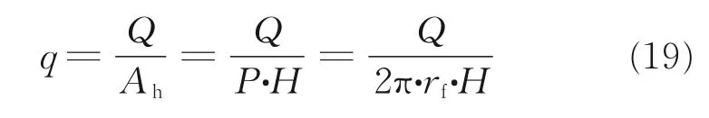
whereTis the temperature,qthe heat flux,AhandAfthe area of the heating film and the cross-sectional area of packaging housing,respectively.Substituting Eqs.(4)—(6)into Eq.(3),the energy balance equation can be written as

The perimeter of the heating film isP,then dAh=Pdy,thus Eq.(7)can be further simplified as

Considering the constantn=qP kfAf,Eq(.8)can be written as

The two boundary conditions are

whereTbis the temperature at the bottom of the piezoelectric stack.
According to the above derivation,the temperature distribution function of piezoelectric stack in the axial direction can be solved from Eqs.(9)and(10).

The heat fluxqis determined based on its concept

wherelfis the length of the packaging housing,Qthe heat generated by the heating film,and thus the constantncan be solved.Besides,the only unknown parameter in the temperature distribution function(Eq.(11))is the temperature valueTb.
Since the bottom of packaging housing with small size is also covered by the heating film,it can be claimed that the bottom temperature of the packaging housing is equal to the bottom of the piezoelectric stackTb.As shown in Fig.4,the heat is transferred to external environment through the mechanical structure.
Here,T0is the temperature of external environment with heat transfer coefficienth0.Tmis the temperature at the top of the mechanical structure,which is lower thanTbbecause of the thermal contact resistance between the two different structures.

Fig.4 Schematic diagram of heat conduction of the structure bottom
Based on the concept of the thermal contact resistance per unit areaRc[23],the heat conduction formula through the thermal contact resistance is obtained as

whereAhbis the area of the bottom packaging housing.The heat conduction formula through the mechanical structure is obtained as follows,which is regarded as the one-dimensional steady-state conduction through the plane wall.

whereAm,rm,kmandlmare the area,radius,thermal conductivity and thickness of the mechanical structure,respectively.Then the temperature valueTbcan be calculated in a combination of Eqs.(13)and(14).

Parameters mentioned above are listed in Table 1.
The packaging housing is made of stainless steel,so the thermal contact resistance per unit areaRccan be calculated according to the empirical value between stainless steel at normal pressure and surface roughness[24].The mechanical is made of Invar with low thermal expansion to accommodate cryogenic temperature.The thermal conductivity of the piezoelectric stackkpcan be obtained from the company’s product manual.The low temperature test chamber used for testing whose available lowest temperatureT0is 70℃.That is to say,under that circumstance the convective heat transfer is forced convection,and the heat transfer coefficienth0can be determined according to the empirical value[23].Relevant thermophysical properties mentioned above are listed in Table 2.
When the thermal power of heating filmQis 2.7 W,the bottom temperature of the stackTb=-45.8℃,which can be obtained on the basis of Eq.(15),then the axial temperature distribution of piezoelectric stack can be obtained by substituting the bottom temperatureTbinto Eq.(11),as shown in Fig.5.

Fig.5 Temperature distribution of piezoelectric stack in the axial direction under whole heating condition
It can be inferred that the axial temperature gradient is quite large under overall heating condition,with the maximum temperature difference of 61℃,which may be harmful to itself.
(1)Different degrees of thermal expansion and change of the preloading force will be triggered due to the large temperature gradient which will further impose great impact on its driving capability ultimately.
(2)The gradient distribution of the piezoelectric constant will be present in the axial direction,which is influential to the driving capability as well.
1.2.2 Local heating theoretical analysis
Since the heat loss mainly comes from the bottom of the piezoelectric stack,for the purpose of reducing the temperature gradient,it is considered to adopt a local heating method,which means that the heating film covers only the bottom of the piezoelectric stack.The length of the heating film isH,and the length of the heating film covering area isHp.
Similarly,based on the above three simplifying assumptions,it is assumed that the temperatures of the package housing and the piezoelectric stack are equal in the same cross section.The packaged housing cover by the heating film(in the black dotted rectangle)is selected as the analysis object.
The piezoelectric stack is divided into a heating section(0≤y≤Hp)and an unheated section(Hp<y≤lp)as shown in Fig.6.
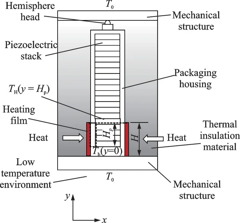
Fig.6 Local heating thermal conductivity model
The heat conduction equation is the same as Eq.(9),but the boundary conditions in the heating section are different.

Then the temperature distribution function of piezoelectric stack in the axial direction can be solved from Eqs.(16)and(17).

The heat fluxqcan be determined as
WhenHp<y≤lp,the energy balance equation is as follows
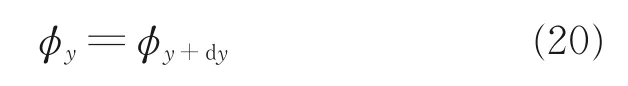
By substituting Eqs.(4)and(5)into the energy balance Eq.(20),the heat conduction equation in the unheated section can be obtained as

The boundary conditions are

The temperature distribution function in the axial direction can be solved from Eqs.(21)and(22).
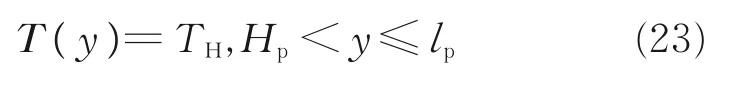
Eq.(23)shows that temperature distribution is uniform in the unheated section,and the temperature value is equal to the temperature ofTH.Therefore,the temperature distribution function can be solved by the calculation ofTHandTb.
According to the Fourier’s law,the heat of the heating section can be obtained from Eq.(18).
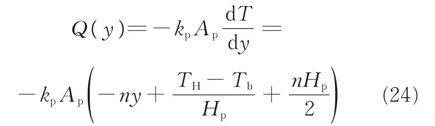
Wheny=Hp,the heat is

Since the temperature in the unheated section is uniform,namely the temperature gradient and the heat input in this section are zero,Eq.(25)can be set to 0.
The whole generated heat is transferred to the external environment through the bottom of the stack due to the fact that the heat input in unheated section is zero,so the temperature valueTbcan be calculated by Eq.(15)as well.In consequence,the axial temperature distribution of the stack under local heating condition can be acquired by substituting the temperature valueTHandTbinto Eqs.(18)and(23).
It is further necessary to determine the power and size of the heating film so that the piezoelectric stack can satisfy the following requirements:(1)Its temperature is higher than 0℃;(2)the axial temperature gradient is small.
With regard to the size of the heating film,the width is determined by the perimeter of the piezoelectric stack.According to the result of the whole heating theoretical model,it can be inferred that under the constant heating power,the smaller the length of the heating film is,the smaller the stack temperature gradient is.Through the investigation,the length of the heating filmHis 10 mm,which is the minimum size of heating film available in the market,and the thickness of the bottom packaging housing is measured as 4 mm,so the length of the heating sectionHpis 6 mm.
Regarding the power of the heating film,for the reason that the bottom temperature of piezoelectric stack descends to its lowest point on the basis of the calculated results,the whole temperature of the stack should be higher than 0℃provided that the bottom temperature is higher than 0℃.Taking the temperature value at the height of 1 mm,the power is 7.2 W,which can ensure that the bottom temperature is not lower than 0℃by setting theT(0.001)=0℃.The heating power is set toQ≥7.3 W in practice.
According to the two temperature distribution Eqs.(18)and(23),the temperature gradient only exists in the heating section,and the temperature difference between two ends of the heating section is the maximum.Therefore,by calculating temperatures at the height of 1 mm and 6 mm,we can acquire the minimum temperature difference(ΔTmin=12.8℃)when the heating power is the minimum value(Q=7.3 W).In conclusion,when the heating powerQand the lengthHof heating film are 7.3 W and 10 mm respectively,a minimum temperature gradient of the piezoelectric stack can be attained,which is satisfying.The axial temperature distribution of piezoelectric stack is shown in Fig.7.
Comparing two heating modes,as shown in Fig.8 and Table 3,it can be conclude that,after adopting the local heating mode,the maximum temperature difference of the stack can be reduced by 80%,and the two requirements mentioned above can be achieved.

Fig.7 Temperature distribution of piezoelectric stack in the axial direction under local heating condition

Fig.8 Comparison of the axial temperature distribution of piezoelectric stack under two heating conditions

Table 3 Comparison of two heating modes ℃
2 Experiments
2.1 Experimental setup
For the sake of verifying the effectiveness of the heating and insulation structure,it is part and parcel to measure the temperature as well as the properties of the piezoelectric stack.To be exact,the electromechanical properties of the piezoelectric stack are described by three sets of matrix coefficient values describing the piezoelectric,dielectric and elastic properties of the stack[7].A piezoelectric stack produced by Harbin Core Tomorrow Science and Technology Co.,Ltd,is put to use in this experiment,which is a conventional piezoelectric stack with a packaging housing(PSt 150/10×10/20),as shown in Fig.9.
In addition,an impedance analyzer(ZX80A-5M)manufactured by Changzhou Zhixin Precision Electronics Co.,Ltd,a low-temperature test chamber(HRH0270type)and a temperature sensor(WZP)are adopted.The conventional piezoelectric stack pasted by a heating film(HXDR-PI)at the bottom is installed inside of the mechanical structure.In detail,the rated power of the heating film which is made of polyimide is 10 W,and the resistance is 30Ω.What’s more,two thermocouple probes,which are connected by two digital multimeters(LINI-T UT71C and FLUKE 17B),are installed at the top and bottom of the packaging housing respectively to measure the temperature at both ends,as shown in Fig.10.Then the stack,wrapped by a layer of thermal insulation material as described before,is connected to the impedance analyzer.Furthermore,the mechanical structure is pasted with a temperature sensor to measure its surface temperature.All data cables connect the internal measured stack with the external instruments through the hole at the side of the test chamber.Fig.11 displays the experimental arrangements in detail.

Fig.10 Diagram of piezoelectric stack temperature test

Fig.11 Display of the experimental devices
For further research,it is significant to compare the experimental results with and without the warming structure,while the used conventional piezoelectric stack will sustain a damage when it is directly exposed to cryogenic environment.Therefore,another low-temperature-resistant piezoelectric stack without a packaging housing(Harbin Core Tomorrow Science and Technology Co.,Ltd.PSt 150/20)which can be exposed to low temperature is employed in the experiment without the warming structure,as shown in Fig.12.

Fig.12 Two kinds of piezoelectric stacks
Additionally,the materials of the two stacks are exactly the same so that the properties including piezoelectric constant,elastic compliance,relative dielectric constant and electromechanical coupling coefficient could be compared,which can guarantee the validity of the comparison of the results.
As described before,the low-temperature-resistant piezoelectric stack is put in the low-temperature test chamber,and then the impedance analyzer and the temperature sensor are utilized to test its properties and surface temperature separately.The piezoelectric stack is connected to the impedance by the cable which is packaged with the thermal insulation material to protect it from the low temperature.The experimental facilities are shown in Fig.13.

Fig.13 Experimental setup without the warming structure
2.2 Experimental results and discussion
2.2.1 Temperature testing results
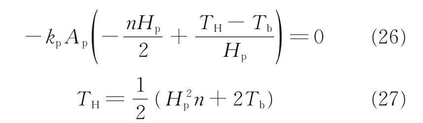
In the experiment,four different temperatures are measured varying with time,including the bottom and top temperatures of the conventional piezoelectric stack,the surface temperature of the mechanical structure as well as the ambient temperature.Specifically,the ambient temperature inside the chamber could be reduced from 20℃to-70℃by control and then maintained at-70℃for 1 h in order to reach the steady-state conduction.The heating film generates the heat increasing gradually as the ambient temperature declines by adjusting the excitation voltage of the DC power supply(IT6302),in order to keep stack’s temperature as steady as possible.As for the heating power of the heating film,it is maintained at 7.3 W eventually in line with the results of theoretical analysis.Each temperature value is recorded at every two-minute interval during the decline of ambient temperature,as shown in Fig.14.
It can be inferred that the surface temperature of the mechanical structure drops along with the decrease in the ambient temperature.Meanwhile,the top and bottom temperatures of the piezoelectric stack,however,are almost stable.The bottom temperature drops a little due to more heat loss at the bottom but it is still above 0℃,which proves that the temperature of piezoelectric stack can remain normal under low temperature environment.Besides,it is clear from Fig.14 that the temperature of the piezoelectric stack could still be maintained normal for a long time after that the ambient temperature has dropped to-70℃,which could reflect the thermal stability of the warming structure.
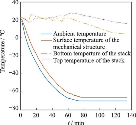
Fig.14 Comparison of the four different temperatures variation with time
The comparison between the theoretical and experimental results of the top and bottom temperatures of piezoelectric stacks,as shown in Table 4,indicates that as far as the temperature at both ends of the stack is concerned,the theoretical results are consistent with the experimental ones with a maximum temperature difference of 3.4℃.

Table 4 Comparison between the theoretical and experimental results ℃
In consequence,the consistency between the measurement results and theoretical results has verified the correctness of the theoretical analysis.
2.2.2 Properties measurement
The elastic,dielectric,and piezoelectric coefficients of piezoelectric ceramics are determined by the resonance method,outlined in the IEEE Standard 176[25]which is able to determine the material properties of piezoelectric stack as well[22].The range of testing frequency,including the fundamental resonance frequencyfrand anti-resonant frequencyfaof the stack,is 10—26 kHz.With the change of the ambient temperature at which the resonance measurement is taken,the properties of the piezoelectric stack are calculated through the following equations[26].


Table 5 Parameters of piezoelectric stacks
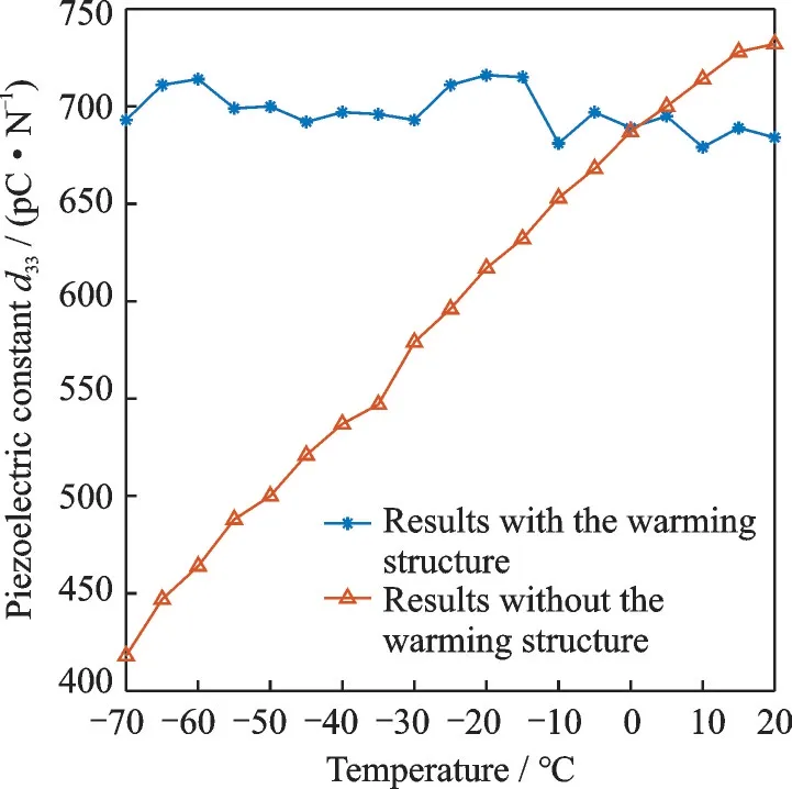
Fig.15 Comparison of the temperature dependence of the piezoelectric constant with or without the warming structure

Fig.16 Comparison of the temperature dependence of the elastic compliance with or without the warming structure

Fig.17 Comparison of the temperature dependence of the relative dielectric constant with or without the warming structure

Fig.18 Comparison of the temperature dependence of the electromechanical coupling coeffcient with or without the warming structure
It can be observed that when the piezoelectric stack is installed with the warming structure,the properties are almost invariable and not affected by the ambient temperature drop,which verifies the feasibility of the heating and insulation structure within the range from normal temperature to-70℃.Relatively speaking,the properties all decrease 40% approximately as the ambient temperature declines when the piezoelectric stack is directly exposed to low temperature environment,which has been mutually verified with Ref.[27].According to the local heating thermal conductivity model,the size and heating power of a heating film can be estimated and chosen on account of such factors as the ambient temperature,heat transfer coefficient as well as the required temperature of the piezoelectric stack,etc.Consequently,this heating and insulation method could be universally adapted and is also applicable for other ambient temperature conditions,so long as some essential adjustments of design are made.On the aforementioned basis,it is imperative to continue developing a warming structure that is applicable in lower temperature environment using a chamber cooled by liquid nitrogen in recent future.
3 Conclusions
A warming structure for the piezoelectric stack applied in low temperature has been successfully designed in this paper.Thermal conductivity models under two different heating modes are analyzed and validated by testing as well.In addition,heating and insulation experiments have been conducted to measure the variation of the temperature and the properties of piezoelectric stack with ambient temperature drop and the experiment without the warming structure performed for comparative purposes.In conclusion,the results reveal that the theoretical analysis are consistent with the experimental results closely.Furthermore,the properties are kept stable for a long period of time as temperature varying from normal temperature to-70℃,which confirms the effectiveness and reliability of the structure.Consequently,the design philosophy has highly significant reference under different temperatures.In short,this structure can be popularized and widely implemented in lower temperature environments.
AcknowledgementsThis work was supported by the National Natural Science Foundation of China(No.11872207),the Aeronautical Science Foundation of China(No.20180952007),the Research Fund of State Key Laboratory of Mechanics and Control of Mechanical Structures(No.MCMS-I-0520G01),and the Key Laboratory Foundation of Equipment Pre-Research(No.6142204200307).
AuthorsMs.LIN Yufan received her B.S.degree in aerocraft design from Nanjing University of Aeronautics and Astronautics(NUAA)in 2018,and joined the State Key Laboratory of Mechanics and Control of Mechanical Structures as a postgraduate student.Her main research field is smart materials and structures.
Prof.SHEN Xing received the Ph.D.degree from NUAA in 2003.He is now a professor of NUAA.His research is focused on Aeronautical smart structure,which includes design and test of the piezoelectric ceramics,piezoelectric sensors and actuators and relative research in the smart materials and structures.
Author contributionsMs.LIN Yufan complied the theoretical model,conducted the analysis,completed the tests and wrote the manuscript.Dr.QIN Xuguo contributed to the investigation of the study.Mr.YU Yi assisted with theoretical analysis and revision of the manuscript.Prof.SHEN Xing designed the study,reviewed the manuscript and provided advices.All authors commented on the manuscript draft and approved the submission.
Competing interestsThe authors declare no competing interests.
杂志排行

Transactions of Nanjing University of Aeronautics and Astronautics的其它文章
- Progress of Chinese“Dove”and Future Studies on Flight Mechanism of Birds and Application System
- Probabilistic Tolerance Method for Omitting Small Fatigue Loads
- Numerical Study on Influence of Key Parameters of Aerodynamic Characteristics of Shaftless Ducted Rotor
- Uncertain Modal Analysis of Unmanned Aircraft Composite Landing Gear
- An h-Adaptivity DG Method on Locally Curved Tetrahedral Mesh for Solving Compressible Flows
- Geometrically Nonlinear Random Responses of Stiffened Plates Under Acoustic Pressure