Study on Wave Added Resistance of a Deep-V Hybrid Monohull Based on Panel Method
2020-09-29WANGXujieZHAOJingZHANGHuidongCAOPengfeiandLIUPeng
WANG Xujie, ZHAO Jing, ZHANG Huidong,*, CAO Pengfei, and LIU Peng
Study on Wave Added Resistance of a Deep-V Hybrid Monohull Based on Panel Method
WANG Xujie1), ZHAO Jing2), ZHANG Huidong1),*, CAO Pengfei3), and LIU Peng1)
1)College of Engineering, Ocean University of China, Qingdao 266100, China 2) College of Electromechanical Engineering, Qingdao University of Science and Technology,Qingdao 266100, China 3) Shipping Center, Ocean University of China,Qingdao 266100, China
In this paper, a panel method based on three dimensional potential flow theory is used to study the problem of wave added resistance. The time-domain motion response of Wigely III ship in head waves is calculated by AQWA, and then the wave added resistance of ship is obtained by near-field pressure integration method. By comparing the calculated results with the experimental data in literature, it is shown that the variation trend and peak value are in good agreement, and the accuracy and efficiency meet the research requirements. Based on the above mentioned method, the wave added resistance of a deep-V hybrid monohull in head waves is studied. The motions and wave added resistances of the deep-V hybrid monohull and the deep-V original ship advancing in head waves with various forward speed and wave frequencies are calculated and analyzed. The results show that the longitudinal motion response of the deep-V hybrid monohull is effectively suppressed and the wave added resistance is obviously reduced, the new type of ship has good engineering application prospects. The present method provides an approach of satisfactory accuracy and efficiency to predict wave added resistance of ships voyaging in waves.
wave added resistance; panel method; hybrid monohull; time-domain motion response; near-field method
1 Introduction
When sailing in waves, the ship will have heave, pitch, roll and other motions, which will cause an increase in resistance comparing with that in calm water. Research shows that the magnitude of wave added resistance could reach 10%-30% of calm water resistance. With the increasing pressure of energy and environmental protection, IMO has proposed the EEDI formula of the newly built ships, which restricts the energy consumption standard of civil ships more strictly. Therefore, wave added resistance is one of the important factors that should be taken into account in ship’s design and optimization stage.
Wave added resistance is the component of the steady second-order wave force in the longitudinal direction, which is essentially a nonlinear force. The calculation methods can be generally classified into two categories, namely far-field and near-field methods. The far-field method was firstly introduced by Maruo (1960), and is based on considerations of the diffracted and radiated wave energy and momentum flux at infinity, leading to the steady added resistance force by the total rate of momentum change. The first near-field method was pro-posed by Boese (1970), which directly integrate the steady second-order pressure acting on the wetted hull surface to obtain wave added resistance. At the initial stage, most of the calculation methods are based on strip theory. Faltinsen. (1980) calculated added wave resistance by integrating pressure on average wetted surface of ship hull based on strip method. Arribas (2007) produced a comparison of different methods for the added resistance by using strip theory. With the development of 3D potential flow theory and the improvement of computer performance, 3D time/frequency domain boundary element methods has been widely applied. Joncquez (2009) formulated the added resistance based on the Rankine panel method using a time-domain approach with B-spline functions. Liu. (2011) employed a 3D frequency domain panel method and a hybrid time domain Rankine source solver based on Green functions and a far-field approach to calculate wave added resistance. Kim and Kim (2011) adopted 3D ranking panel method in time domain in hydrodynamic calculation for voyaging ship and then obtained added resistance by integration of pressure on wetted surface of ship hull. Söding. (2014) computed the wave added resistance based on a frequency domain Rankine panel method that accounts for the dynamic squat of the ship and the effects of the nonlinear steady flow caused by the ship’s forward speed. Hong. (2016) calculated the wave added resistance of the ship based on a three-dimensional translating and pulsating source panel method. Park and Kim (2016) used Rankine source method to solve the motion responses of the ship in head waves, and used the near-field method to obtain wave added resistance, which achieved good prediction accuracy.
With the rapid development of computational facilities, CFD methods are now increasingly applied used to predict added resistance and ship motions. Sadat-Hosseini. (2010) predicted the added resistance and motions for KVLCC2 in head waves based on a Unsteady Reynolds- Averaged Navier-Stokes approach. Guo. (2012) investigated the added resistance, ship motions and wake flow of KVLCC2 in head waves with systematic validation and verification of the numerical computation. Yang and Kim (2017) used a Cartesian-grid method to investigate the added resistance of KVLCC2 with different bows in short waves. Compared to potential flow methods, CFD approaches provide a more accurate description of the physical phenomena,but the computations require large computational resources and the accuracy depends heavily on the user’s experience.
AQWA is a mature hydrodynamic analysis software in the field of ship and ocean engineering. Based on the three-dimensional potential radiation-diffraction theory, it can calculate the motion response and wave load of floating structures in frequency domain and time domain. In this paper, the motion responses and wave added resistance of Wigley III hull advancing in waves with various forward speed are carried out in time domain by using AQWA. By comparing the calculated results with the experimental data in literature, it is shown that the variation trend and peak value are in good agreement, and the accuracy and efficiency meet the research requirements. Then the motion responses and wave added resistance of a type of deep-V original ship and deep-V hybrid mono- hull are calculated and compared. The study shows that the composite appendage of hybrid monohull can obviously reduce the longitudinal motion of the ship, and improve the sea-keeping performance and resistance performance of the ship.
2 Basic Formulation
A coordinate system is introduced, as shown in Fig.1. The-plane coincides with the calm water free surface with the-axis pointing towards the bow and the-axis pointing upwards. The translatory displacements in the,anddirections are1(surge),2(sway) and3(heave), and the angular displacements of rotational motion about the,, andaxes are4(roll),5(pitch) and6(yaw) respectively.
The potential flow theory considers that the fluid is incompressible and inviscid, and the flow is irrotational. A potential function can be used to describe the distribution of velocity in the flow field, which not only satisfies the Laplace equation, but also satisfies corresponding initial conditions and the boundary conditions. The total potential Φ(,,,) in the flow field can be written as:

The periodic potential can be separated into three parts: the incident wave potential, the diffraction potential and the radiation potential:

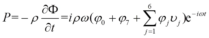
where0is the incident wave potential,7is the diffraction potential of the restrained ship,φis the normalized velocity potential due to forced motions in six degrees of freedom,νis the complex amplitude of theth degree of freedom,is incident wave frequency.
For diffraction and radiation wave potential, the boun- dary value problem to be solved is:
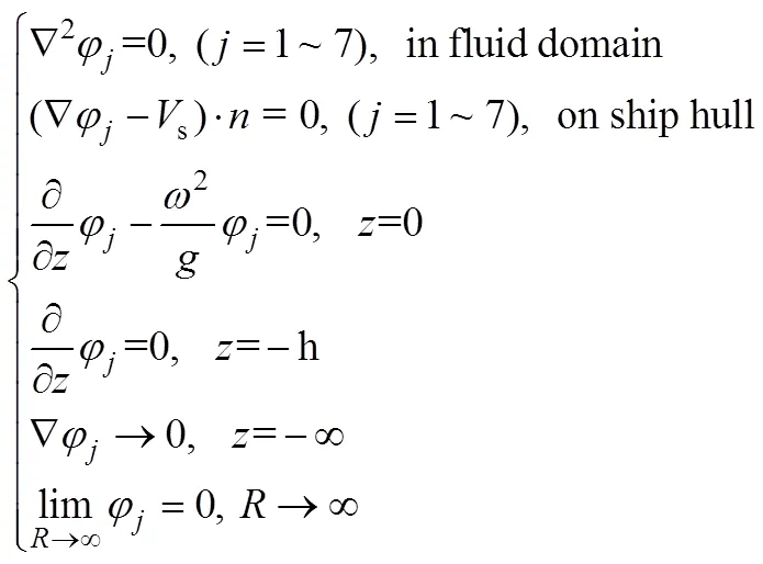
The boundary element method based on three-dimensional source and sink distribution theory can be used to solve the above velocity potential. The velocity potential can be expressed as:
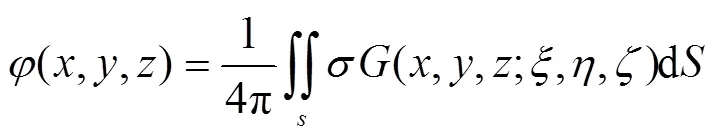
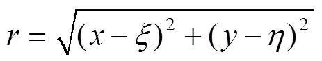
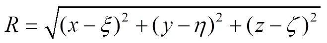
whereis source strength,is wetted surface, (,,) is the coordinate of the field point in the flow field, (,,) is the coordinate of the source point on,is Green’s function.satisfies all boundary conditions, and can be expressed as:
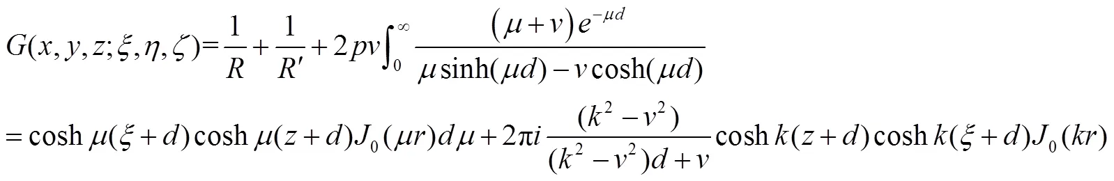


whereis the principal value of the integral,0is the first term of the Bessel function.
Then the first-order hydrodynamic pressure distribution of the hull can be obtained from the Bernoulli equation as follow:
By integrating the pressure along the wetted surface of the hull, the hydrodynamic force acting on the hull can be obtained. The longitudinal component of the hydrodynamic force is wave added resistance, which can be divided into three parts: incident force, diffraction force and radiation force.


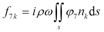
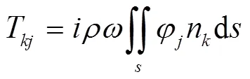
where0kis incident force,7kis diffraction force,Tis the radiation force ofdirection when floating body moving at unit velocity indirection.
The differential equation of motion of a ship advancing in regular waves is:

whereMis structural mass matrix,Mis hydrodynamic additional mass matrix,is linear damping matrix of the system,Kis total stiffness matrix of the system,is wave force on the system,is response amplitude operator (RAO),is incident wave frequency.
3 Calculation of Wigley III Hull
Firstly, the motion response and wave added resistance of Wigley III hull advancing in waves with various forward speed are carried out and analyzed.
3.1 Hull Geometry Model of Wigley III
The Wigley III hull surface is defined by the following expression:
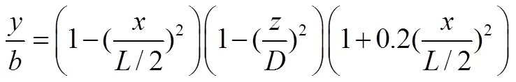
where 2/=0.1 and/=0.0625.
Fig.2 show the body plans of Wigley III hull. The principle dimensions of the ship are given in Table 1.
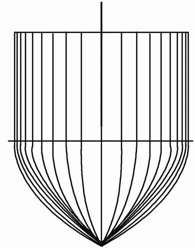
Fig.2 The body plan of Wigley III.

Table 1 Main parameter of Wigley III
Fig.3 shows the geometric models of the Wigely III ship, which are built in proportion to 1:1 by AQWA. The number of grids is 3250.

Fig.3 Model and grids of Wigley III.
3.2 Numerical Validations
After the modeling and grid partitioning are completed, the response amplitude operators of six degrees of freedom for the hull under different frequency waves and forward speed are calculated by using AQWA-LINE module. Then the ship’s motion responses and wave forces at several wave frequencies and Froude numbers in time domain are calculated by using AQWA-NAUT module. Finally, the calculation results and experimental data are compared and analyzed.
The motion responses and wave added resistance of the Wigely-III hull advancing in regular head waves at=0.2, 0.3 and 0.4 are calculated respectively, and the range of/is 0.5-2.5, whereis wave length andis ship length between perpendiculars. Due to the limitation of space, only the results at=0.3,/1.3 are listed. Figs.4 and 5 present time histories of computed heave and pitch motions for the Wigely-III hull in regular head waves respectively. Fig.6 presents time history of com- puted longitudinal wave force on the ship. Due to the symmetry of the hull and the flow field, the roll motion response of the ship is close to zero(Faltinsen., 1980).
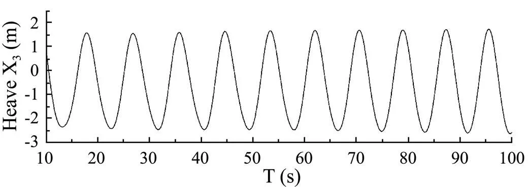
Fig.4 Heave response of Wigely-III (Fn=0.3, λ/L=1.3).
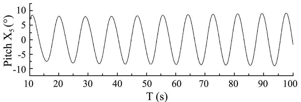
Fig.5 Pitch response of Wigely-III (Fn=0.3, λ/L=1.3).

Fig.6 Wave forces along the longitudinal direction of Wigely-III (Fn=0.3, λ/L=1.3).
Figs.7-9 show the calculation results of wave added resistance of the Wigely-III ship at=0.2, 0.3 and 0.4. It can be seen from the figures that the variation trend of the calculation results are in good agreement with the experimental results.
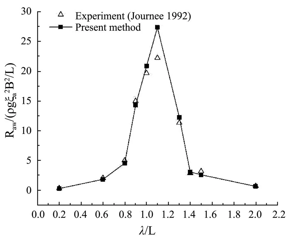
Fig.7 Wave added resistance of Wigely-III(Fn=0.2).

Fig.8 Wave added resistance of Wigely-III(Fn=0.3).
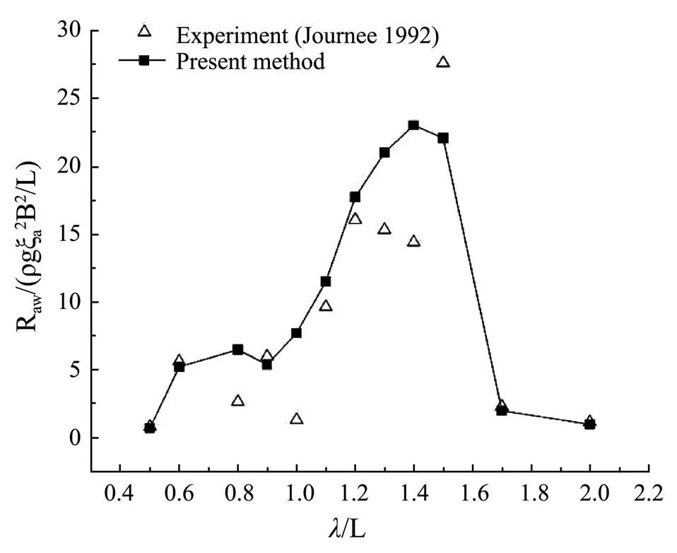
Fig.9 Wave added resistance of Wigely-III (Fn=0.4).
4 Calculation of Deep-V Original Ship and Hybrid Monohull
4.1 Hull Geometry Model of Deep-V Original Ship and Hybrid Monohull
A type of hybrid monohull has been developed by Li Jide. It has deep-V shaped hull and a composite appen- dage which consists of central body and a pair of fins under the stem. Fig.10 shows the body plans of deep-V original hull. Fig.11 shows the form of deep-V hybrid monohull.
The principle dimensions of the hybrid monohull are given in Table 2. The deep-V original ship has the same principle dimensions, but without the composite appen- dage under the baseline.
The composite appendage is composed of a central body and a pair of triangular fins on both sides. The dimensions of the central body and fin are given in Tables 3 and 4.
Figs.12 and 13 show the geometric models of the deep- V original ship and hybrid monohull, which are built in proportion to 1:1 by AQWA. The grids number of two models is 12260 and 9211 separately.

Table 2 Main parameter of hybrid monohull
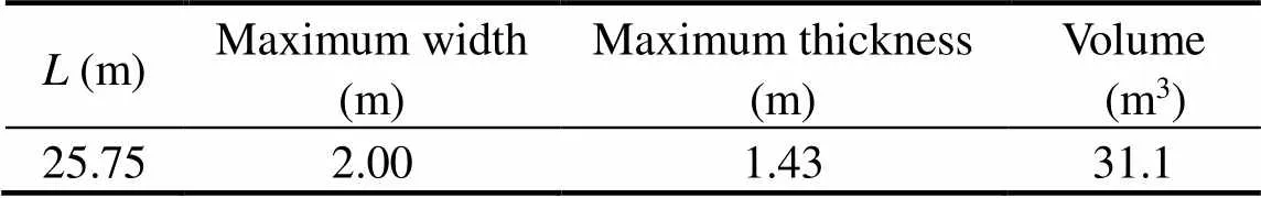
Table 3 Dimension of the central body
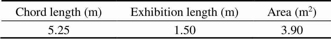
Table 4 Dimension of the fin
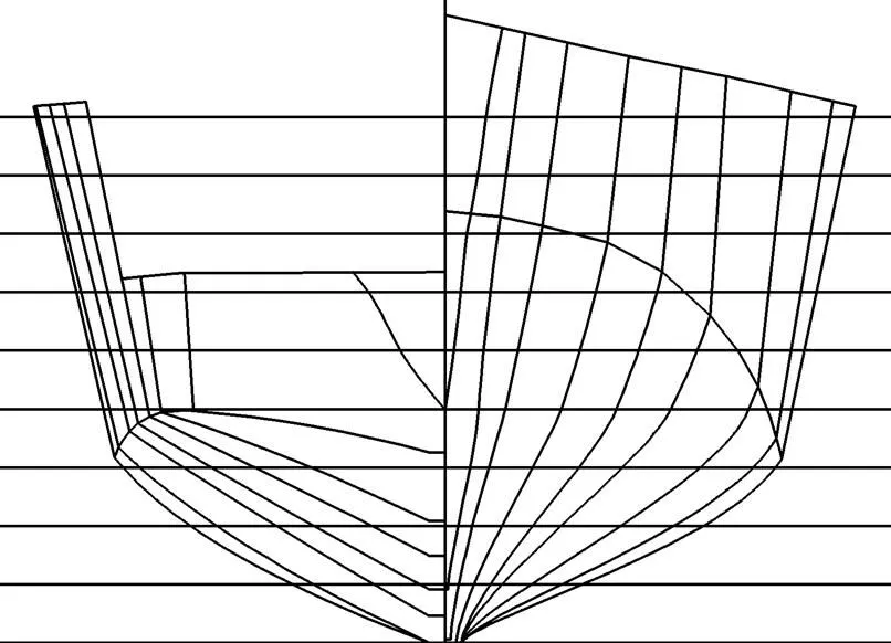
Fig.10 Body plans of deep-V original hull.
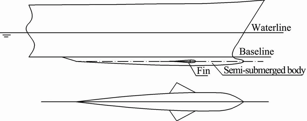
Fig.11 Form of deep-V hybrid monohull.
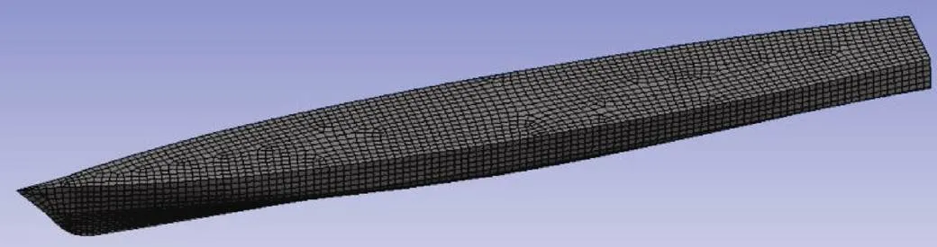
Fig.12 Model and grids of deep-V original ship.
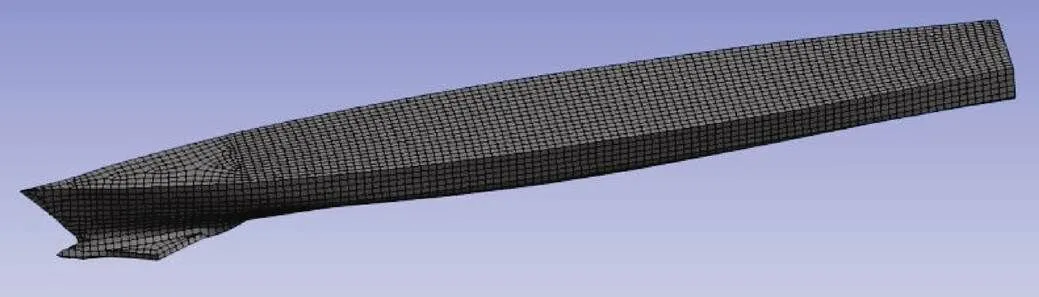
Fig.13 Model and grids of deep-V hybrid monohull.
The deep-V original ship and hybrid monohull are cal- culated for the motion response and wave added resis tance at=0.32, 0.43 and 0.53. Time histories of com- puted heave, pitch motions and longitudinal wave force of two models at=0.43,/1.4 are shown in Figs.14-16.

Fig.14 Heave response of deep-V original ship and hybrid monohull (Fn=0.43, λ/L=1.4).
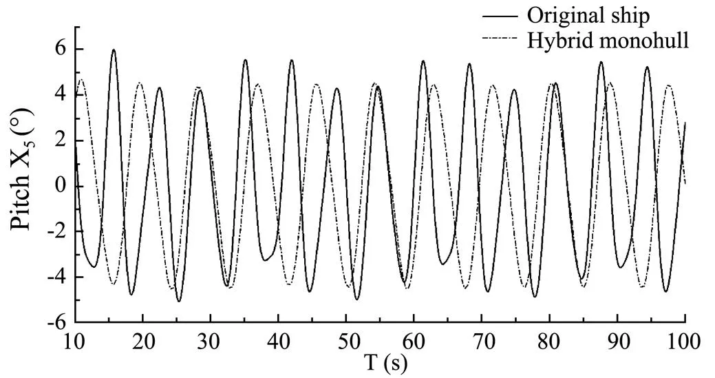
Fig.15 Pitch response of deep-V original ship and hybrid monohull (Fn=0.43, λ/L=1.4).
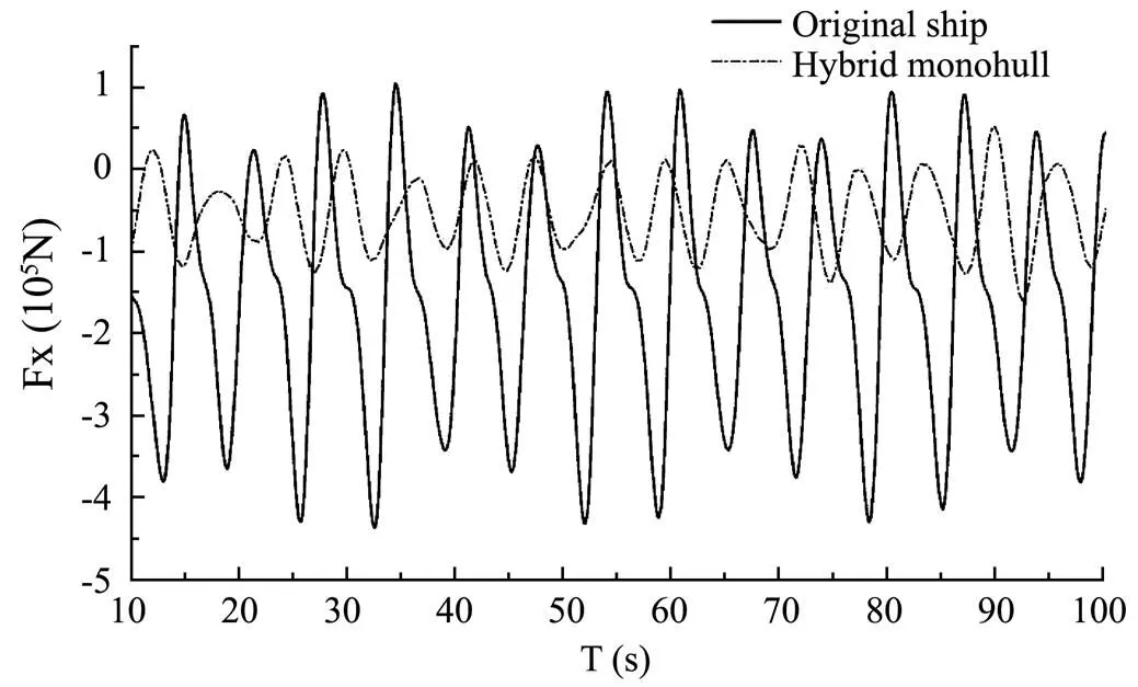
Fig.16 Wave forces along the longitudinal direction (Fn=0.43, λ/L=1.4).
From the time-history curves of the heave motion and pitch motion, it can be seen that the motion amplitude of the deep-V hybrid monohull is apparently smaller than the amplitude of the original ship form. Meanwhile the longitudinal motion response is much more smooth. From the time-history curves of the longitudinal force, it can be seen that both the amplitude and the mean of the wave forces that the deep-V hybrid monohull takes are smaller than those of the original ship. The wave added resistance is reduced significantly.
Figs.17-22 show the comparison between the calcu- lated results and the experimental values of longitudinal motion amplitude and wave added resistance under diffe- rent Froude numbers and/values.

Fig.17 Heave response of deep-V original ship and hybrid monohull (Fn=0.32).
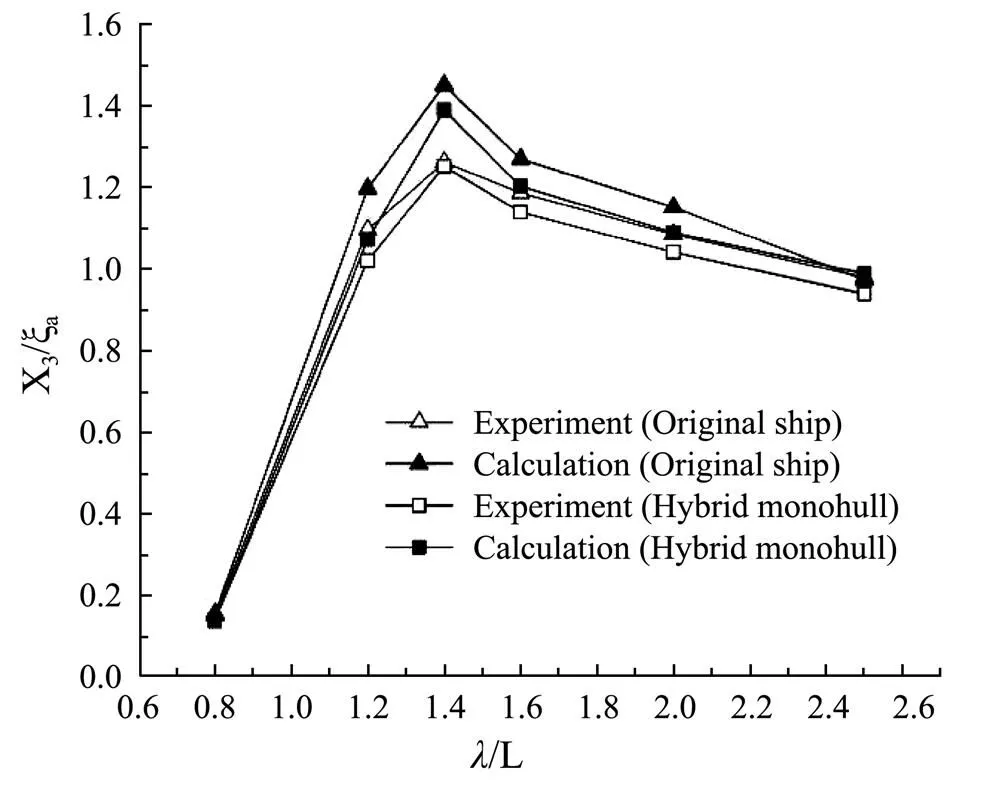
Fig.18 Heave response of deep-V original ship and hybrid monohull (Fn=0.43).
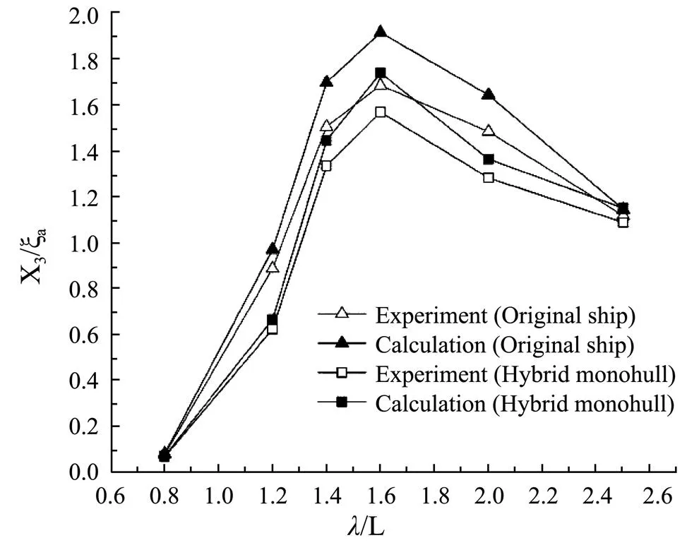
Fig.19 Heave response of deep-V original ship and hybrid monohull (Fn=0.53).
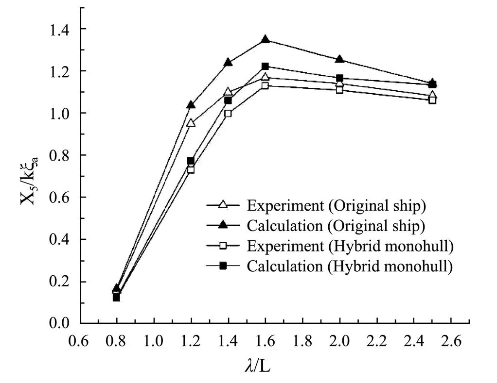
Fig.20 Pitch response of deep-V original ship and hybrid monohull (Fn=0.32).

Fig.21 Pitch response of deep-V original ship and hybrid monohull (Fn=0.43).
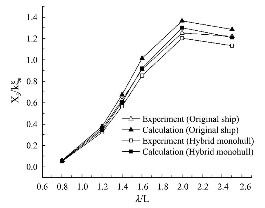
Fig.22 Pitch response of deep-V original ship and hybrid monohull (Fn = 0.53).
Figs.17-19 show the amplitudes of heave motion with regard to the two ship forms. Figs.20-22 show the amplitudes of pitch motion. It can be seen that the calculated results are in good agreement with the experimental values, and the proposed approach in this paper can predict the motion amplitudes of the ship sailing in head waves. Due to the impact of the increase of Froude number on the encounter frequency, the/of peak value also increased. For heave motion, the peak value occurs respectively where/=1.2, 1.4, 1.6 with the constraint of=0.32, 0.43, 0.53. For the pitch motion, the peak value occurs where=1.4, 1.6, 2.0 with the same constraint. By comparing the results with the experimental values, it is found that the calculated result is a little larger than the experimental value. This is because the potential flow theory ignores the viscosity of the fluid. In general, the proposed approach can control the average error within 10% and satisfy the accuracy requirement of the research. The experiment and the numerical calculation show that the heave and pitch motion can be restrained significantly by the composite appendage. The sea-keeping perfor- mance of hybrid monohull is obviously improved compared with the original ship.
Then the wave added resistance of the two ship forms are calculated. Figs.23-25 show the comparison of the calculated values with the experimental values.
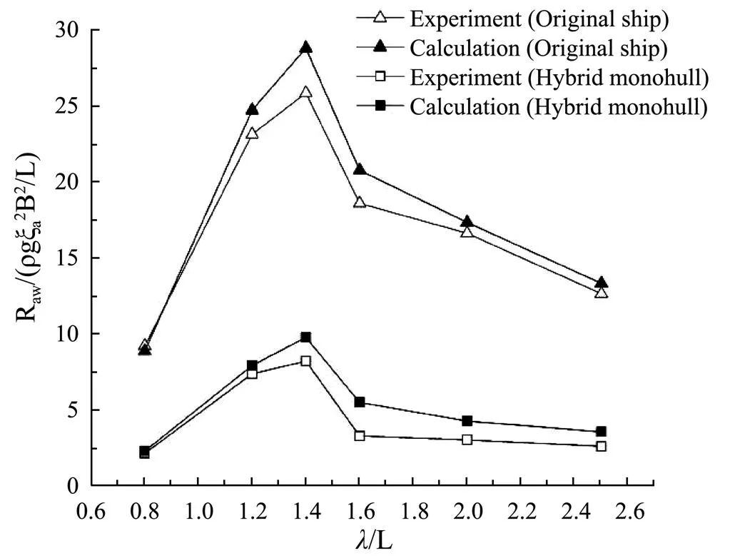
Fig.23 Wave added resistance of deep-V original ship and hybrid monohull (Fn=0.32).
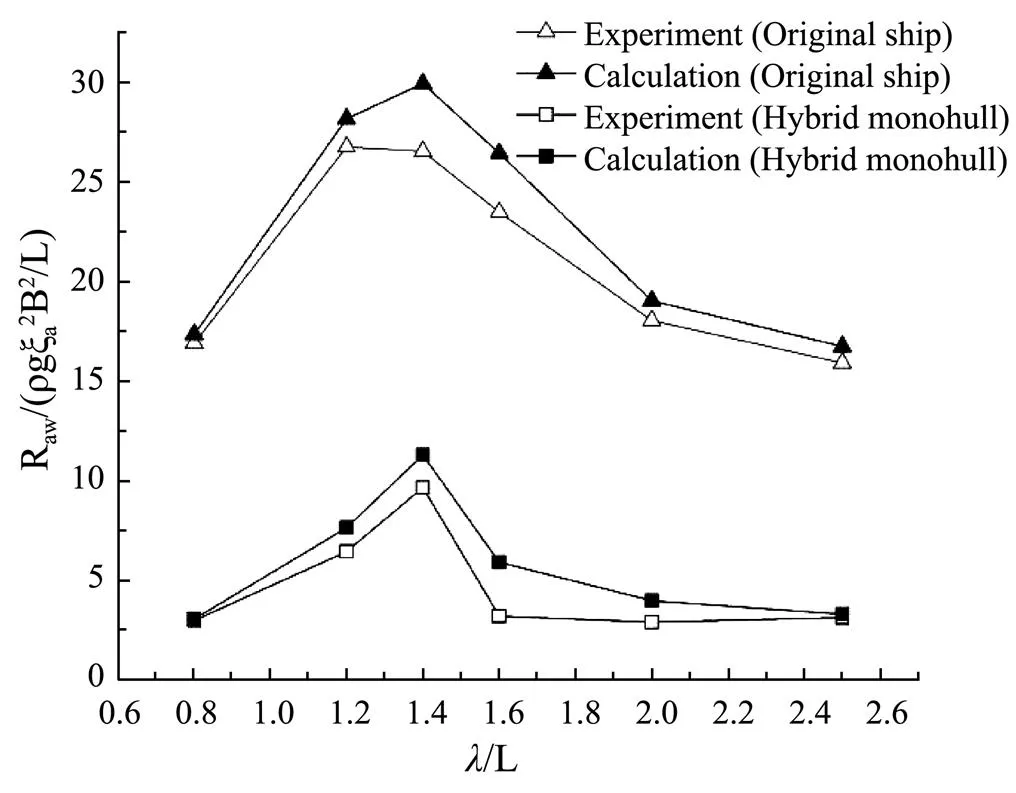
Fig.24 Wave added resistance of deep-V original ship and hybrid monohull (Fn=0.43).

Fig.25 Wave added resistance of deep-V original ship and hybrid monohull (Fn=0.53).
From the results of calculation and experiment, it can be seen that the motion response and wave added resistance of deep-V hybrid monohull are obviously reduced compared with the original hull. This is because the composite appendage will produce vertical resistance when the ship moves longitudinally, which increase the damping coefficient of the ship and reduce the longitudinal motion response. As is known, wave added resistance is composed of two parts, namely diffraction added resistance and radiation added resistance,and when a ship is sailing at high speed in waves, the wave added resistance is mainly caused by radiation. Because the composite appendage can suppress the motion response of ship, the wave added resistance of hybrid monohull is greatly reduced simultaneously. When the Froude numbers of the two ships are the same, within the interval where encounter frequency is similar to the inherent frequency of the hull, there are intense heaving and pitching motions, in this case, the reduction of motion response and wave added resistance is the most obvious. With the increase of Froude number, the amplitude of ship motion response increases, and the restraint effect of the composite appendage on motion response and wave added resistance is better.
5 Conclusions
The wave added resistance of three ships under head waves were calculated and compared with test results in this paper, the variation trends of three types were in good agreement, indicating that the panel method based on the potential flow theory can forecast the motion response and wave added resistance of the ship under head waves quite well. The calculation accuracy and efficiency of the method in this paper can meet the requirements of engineering application. Therefore, it can be applied to evaluate the rapidity and economy of a ship, and is applicable for designing new ship types and optimizing the hydrodynamic performance of an existing ship type.
By comparing the longitudinal motion responses of the original ship form and deep-V hybrid monohull in head waves, it can be seen that the composite appendage under the bow can obviously reduce the longitudinal motion of the ship, and make the hybrid monohull have better sea- keeping performance and resistance performance. In the future, the main hull and the composite appendage can be further optimized, and new hull forms with better perfor- mance can be proposed.
With the proposed approach, the wave added resistance of ship can be fast calculated. And also the correlation between wave added resistance, the speed of ship and the wave frequency is analyzed. The analysis in this paper can provide guidance to the selection of ship’s speed and improve the economy of ship’s navigation.
Acknowledgements
The authors wish to acknowledge financial support from the National Natural Science Foundation of China (Nos. 51709246, U1806229, 51809244, and 51609220), and the Fundamental Research Funds for the Central Universities (No. 201713031).
Arribas, F. P., 2007. Some methods to obtain the added resistance of a ship advancing in waves., 34 (7): 946-955.
Boese, P., 1970. A simple method for the calculation of resistance increase of a ship in a seaway., 17 (86): 29-32.
Faltinsen, O. M., Minsaas, K. J., Liapis, N., and Skjørdal, S., 1980. Prediction of resistance and propulsion of a ship in a seaway. In:. Tokyo, Japan, 21-26.
Fujii, H., and Takahashi, T., 1975. Experimental study on the resistance increase of a ship in regular oblique waves. In:. Otawa, Japan, 37-44.
Gerritsma, J., and Beukelman, W., 1972. Analysis of the resistance increase in waves of a fast cargo ship., 19: 285-293.
Guo, B., and Steen, S., 2011. Evaluation of added resistance of kvlcc2 in short waves., 23 (6): 709-722.
Hong, L., Zhu, R. C., Miao, G. P., Fan, J., and Li, S., 2016. An investigation into added resistance of vessels advancing in waves., 123: 238-248.
Joncquez, S. A., 2009. Second-order forces and moments acting on ships in waves. PhD thesis. Technical University of Denmark, Copenhagen, Denmark.
Journee, J. M. J., 1992. Experiments and calculations on 4 Wig- ley hull forms in head waves. Ship Hydromechanics Labora-tory, Delft University of Technology, 0909, 1992.
Kashiwagi, M., Ikeda, T., and Sasakawa, T., 2010. Effects of forward speed of a ship on added resistance in waves., 20 (3): 196-203.
Kim, K. H., Joncquez, S., Kim, Y., and Bingham, H., 2010. Numerical analysis on added resistance of ships in time-domain. In:. Harbin, China, 11pp.
Kim, K. H., and Kim, Y., 2011. Numerical study on added resistance of ships by using a time-domain rankine panel method., 38: 1357-1367.
Kim, M., Hizir, O., Turan, O., and Incecik, A., 2017. Numerical studies on added resistance and motions of KVLCC2 in head seas for various ship speeds., 466-476.
Kuroda, M., Tsujimoto, M., Fujiwara, T., Ohmatsu, S., and Takagi, K., 2008. Investigation on components of added resistance in short waves., 8: 171-176.
Lee, J. H., and Kim, Y., 2017. Study on added resistance of a ship under parametric roll motion., 144: 1-13.
Lee, J. H., Park, D. M., and Kim, Y., 2017. Experimental investigation on the added resistance of modified KVLCC2 hull forms with different bow shapes., 231 (2): 395-410.
Liu, S., Papanikolaou, A., and Zaraphonites, G., 2011. Prediction of added resistance of ships in waves., 38: 641-650.
Maruo, H., 1960. The drift of a body floating on waves., 4 (3): 1-10.
Sadat-Hosseini, H., Carrica, P., Kim, H., Toda, Y., and Stern, F., 2010. URANS simulation and valiation of added resistance and motions of the KVLCC2 crude carrier with fixed and free surge conditions, Gothenburg 2010: A Workshop on CFD in ship hydrodynamics.
Sadat-Hosseini, H., Wu, P., Carrica, P., Kim, H., Toda, Y., and Rn, F., 2010. CFD verification and validation of added resistance and motions of KVLCC2 with fixed and free surge in short and long head waves., 59: 240-273.
Salvensen, N., 1978. Added resistance of ships in waves., 2 (1): 24-34.
Seo, M., Yang, K., Park, D., and Kim, Y., 2014. Numerical analysis of added resistance on ships in short waves., 73: 1-15.
Söding, H., Shigunov, V., Schellin, T. E., and El Moctar, O., 2014. A rankine panel method for added resistance of ships in waves., 136 (3): 1-7.
Wang, X., Sun, S., Zhao, X., Li J., and Luan, J., 2011. Research on model test of thousands-tons class high seakeeping performance hybrid monohull., 15 (4): 342-349.
Wang, X., Zhao J., Liu P., Cao P., and Yu T., 2019. Study on ship added resistance in regular head waves based on Panel Method.. Hawaii, USA.
Yang, K. K., and Kim, Y., 2017. Numerical analysis of added resistance on blunt ships with different bow shapes in short waves., 22: 245- 258.
Yang, K. K., Kim, Y., and Jung, Y. W., 2018. Enhancement of asymptotic formula for added resistance of ships in short waves., 148: 211-222.
. Tel: 0086-532-66781550
E-mail: zhanghuidong@ouc.edu.cn
June 27, 2019;
November 13, 2019;
November 21, 2019
(Edited by Ji Dechun)
杂志排行

Journal of Ocean University of China的其它文章
- Estimation of the Reflection of Internal Tides on a Slope
- The New Minimum of Sea Ice Concentration in the Central Arctic in 2016
- Investigation of the Heat Budget of the Tropical Indian Ocean During Indian Ocean Dipole Events Occurring After ENSO
- Image Dehazing by Incorporating Markov Random Field with Dark Channel Prior
- Biochemical Factors Affecting the Quality of Products and the Technology of Processing Deep-Sea Fish,the Giant Grenadier Albatrossia pectoralis
- Propulsion Performance of Spanwise Flexible Wing Using Unsteady Panel Method