微金字塔阵列结构的飞刀切削技术研究
2020-09-05黄岳田
杜 丹,黄岳田,范 斌
微金字塔阵列结构的飞刀切削技术研究
杜 丹1,黄岳田2,3*,范 斌2
1北京跟踪与通信技术研究所,北京 100094;2中国科学院光电技术研究所,四川 成都 610209;3中国科学院大学,北京 100049
微结构阵列光学元件的加工受到越来越广泛的关注,单点金刚石飞刀切削技术以高效率低成本且加工精度高的优势,逐渐应用于微结构的加工。本文主要研究飞刀切削微金字塔结构时,机床重复定位误差和循环加工引入的误差对微结构切削效果的影响,分析V槽切削时次沟槽产生的条件,研究抑制次沟槽产生方法,实验验证了可以通过控制切削深度大于最小切削深度来抑制次沟槽的产生。
飞刀切削;微金字塔结构;次沟槽;切削深度

1 引 言
微结构阵列光学元件可以实现减反射效应、自聚焦效应、电磁吸收效应和超强光透射效应等光学特性,广泛应用于现代光学系统中,应用对象甚至包括高分辨率生化检测等传感领域,发展前景非常可观[1-3]。光学微结构的加工方法主要有光学光刻、电子束直写、聚焦离子束刻蚀和单点金刚石车削等。
光学光刻加工的微结构尺寸一般在亚微米量级,可加工微结构尺寸还受到光学衍射的物理限制,光的波长决定了其极限加工能力[4]。电子束直写分辨率高,电子比光波还要短许多个量级,因此用电子束[5]可以尽量降低衍射的影响。但是电子束直写效率低下,且受到适用材料范围的局限,仅能在电子敏感聚合物材料上复形。聚焦离子束的方法加工效率较低,难以满足批量生产的需求。同样的,激光加工技术[6-7]在薄膜材料普适性和加工效率方面存在巨大困难与挑战。
上述方法都存在加工材料普适性与加工效率方面的不足。特别是针对渐变轮廓的薄膜光学微结构,光学材料的折射率沿结构法向逐渐变化时,上述加工方法操作起来更为繁琐,且难以保证制备的精度。而单点金刚石车削加工微结构尺寸在微米量级,加工简单且效率高,可以直接在有色金属、红外材料和光学塑料上加工成形,也可以在金属磨具上加工微结构,通过压印等技术实现批量加工,微结构形状精度高。国内外对单点金刚石车削加工微结构展开了相应的研究,如韩国庆尚大学的Le等[8]对车削微结构时产生的毛刺展开研究;上海交通大学的Deng等[9]研究卷轴上车削加工微结构;日本东北大学的Yan等[10]对车削微结构时的应力和温度进行了仿真研究;香港理工大学的Zhu等[11]提出了加工分层微结构的车削方式。目前对微结构的车削研究主要集中在加工工艺的优化,以获得更优的表面质量。本文通过分析微结构车削的尺寸误差来源,研究抑制误差产生条件,以减小尺寸误差对微结构车削结果的影响。微结构飞刀切削一般需要机床四轴联动来实现,现有机床只有三轴联动,因此采用端面切削来实现微结构的飞刀切削。
2 飞刀切削
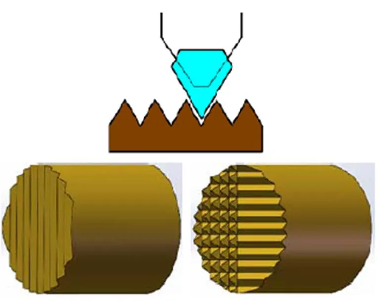
单点金刚石飞刀切削加工如图1所示。金刚石刀具安装在飞刀盘上,飞刀盘装在主轴上随主轴转动,即刀具随主轴旋转切削。工件固定在工作台上,随机床做平面运动。刀具随主轴每转一圈,刀具与工件表面接触一次,车削方式为断续加工。
飞刀切削微金字塔阵列结构加工原理如图2,金刚石刀具安装在飞刀盘上同主轴一起旋转,主轴每转一圈刀具切削工件一次,在工件表面上形成一道V形槽,随刀尖位置移动在工件表面加工出连续的V形槽。然后将工件旋转90°,同样加工一遍,两个垂直方向的V形槽叠加即形成微金字塔阵列结构。
飞刀切削微金字塔阵列结构原理就是把刀尖的形状复刻到工件表面,然后形状叠加而成型。这种方法加工的金字塔形状轮廓精度高,加工效率高。飞刀切削已经广泛应用于V槽阵列和微金字塔阵列结构的加工[10],可以加工的微金字塔结构单元尺寸达10mm。随着应用的需求,扩大切削金字塔的适用范围,研究更小特征尺寸的微金字塔结构加工必不可少。因此展开研究深度方向1mm的微金字塔结构飞刀切削,分析影响切削效果的因素。

图1 飞刀切削加工方式

图2 仿形法飞刀车削微金字塔阵列原理
3 微结构误差分析
微金字塔阵列结构的飞刀切削要先加工出单方向的V槽,再根据设计将工件旋转相应角度加工另一个方向,两个方向的V槽叠加形成相应微金字塔阵列结构,因此微金字塔阵列单元的特征尺寸由单方向的V槽尺寸决定。
仿形法切削加工的V形槽即刀尖形状的复刻,与刀具的形状相同。V形槽的特征尺寸如图3,当刀具刀尖形状确定后,刀尖角度决定了结构尺寸的形状特征,即宽度与高度的比值/固定,如刀具刀尖角度为90°时,/=2。特征尺寸的值通过控制刀具每转进给量来实现,特征尺寸由切削深度控制。在车削V槽时,当切削深度未达到设计尺寸时,即使尺寸的值达到设计值,加工出的V槽会不连续。而切削深度影响车削的表面质量,理论上切削深度越小,切削时产生的力越小,且切削区域温度越低,这样得到的切削表面质量越好[12-13]。
为保证切削表面质量,特征尺寸一般分几次循环加工,直至总切削深度达到值。而循环加工存在的问题是定位误差的影响,在加工微小尺寸结构时效果更明显。

图3 V形槽的特征尺寸示意图
超精密车削过程中,任何微小的误差都会影响最终的切削结果。循环加工微金字塔阵列结构时,机床的重复定位误差是影响微槽切削效果的关键因素。机床重复定位误差主要影响刀具中心的偏移,循环加工起始点位置发生偏移,则加工出的微结构形状会发生变形。
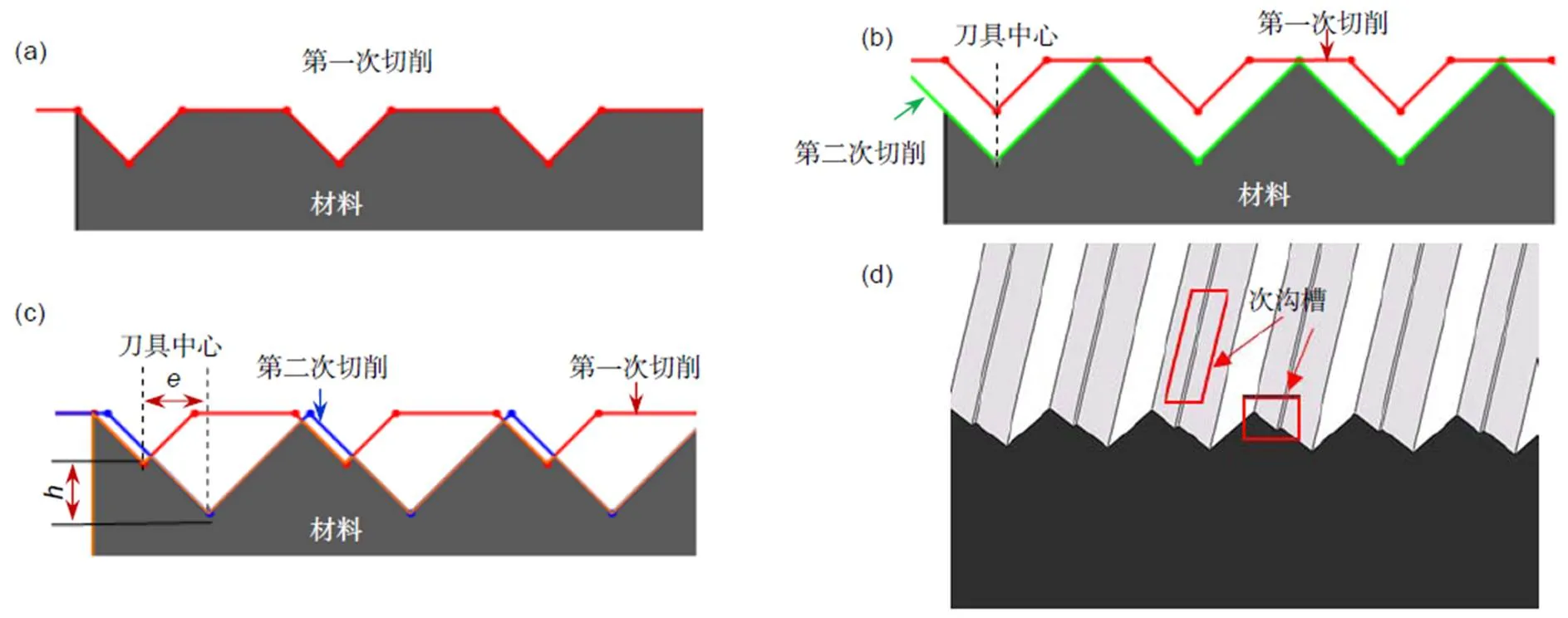
如图4所示,用飞刀切削循环加工相邻的连续V槽,第一次切削深度为V槽深度的一半,加工结果如图4(a)。若切削过程中刀具中心未发生偏移,第二次切削时的刀具在第一次的基础上,在切削深度方向进给,加工出连续的V形槽,如图4(b)。当第二次车削刀具中心发生偏移时,切削效果如图4(c),会在V槽面上产生小凸起,形成次沟槽。其三维仿真结果如图4(d)。次沟槽的产生会影响V槽的成像效果,在加工时是要避免的。

图4 刀具中心偏移对V槽切削效果影响
要减小刀具中心偏移造成的切削次沟槽,分析刀具中心偏移与单次切削深度的关系,如图5,刀具刀尖角度为90°时,循环两次加工V槽结构。
当刀具中心偏移量大于切削深度,如图5(a),第一次切削会有部分残留没有车到,交界处产生次沟槽,次沟槽的位置与两次切削的交界位置相关。当刀具中心偏移量小于切削深度,如图5(b),第二次切削会在第一次切削的轮廓下继续往下切削,不会形成过渡区域,则并没有次沟槽生成。因此要保证没有次沟槽的生成,必须满足刀具中心偏移量小于切削深度。刀具中心的偏移量与加工条件相关,如机床重复定位精度,可以通过实验获得加工时最大的刀具中心偏移量max。这是一个相对固定的值,而切削深度是可以设定的。由此可以得到不产生次沟槽的最小切削深度min:
min=max。
循环加工时只要保证单次切削深度大于刀具中心最大偏移量,则每次切削都不会产生次沟槽。刀具中心偏移误差主要受机床定位误差影响,一般超精密机床定位精度很高,可以达到亚微米级。但循环加工还要考虑重复定位误差,且加工过程中引入的其他环境误差会随循环次数增多而变大。实际的刀具中心偏移量要远大于机床标定的定位精度值和重复定位精度值,因此在实际加工中要找到最小切削深度来保证微结构的切削表面质量。
4 实验与结果分析
理论分析在飞刀加工V槽时,切削深度会影响次沟槽的产生,因此用实验验证切削深度与刀具中心偏移误差的关系。实验机床为Precitech Nanoform 700 ultra,刀具为刀尖角度90°的尖刀,工件材料选用6061铝。本次实验的微V槽阵列特征尺寸横向宽度2mm,深度1mm。加工机床的额定的运动轴定位精度达到0.2mm,实际加工中造成的刀具中心偏移误差会大于这个值,因此实验设计单次切削深度分别为200 nm、500 nm和1mm来飞刀切削微V槽结构。切削实验参数如表1,用相同的加工转速和进给速度加工连续的V槽。
实验结果如图6。图6(a)、图6(b)、图6(c)分别为单次切削深度200 nm、500 nm和1mm的飞刀切削结果。图6(a)和6(b)可以明显看到有次沟槽的产生,且图6(b)中的次沟槽尺寸要略小于图6(a)中的次沟槽。而图6(c)基本没有次沟槽的产生。机床的额定定位精度为200 nm,实际加工中,刀具中心的偏移量显然远大于200 nm。从图6(b)可以估计实际的刀具中心最大偏移量略大于500 nm。因此,当切削深度为1mm,大于刀具最大偏移量时,不会产生次沟槽。而切削深度小于刀具最大偏移量时,次沟槽的大小还与切削深度相关,单次切削深度越小,次沟槽的影响越大。

图5 刀具中心偏移量与切削结果示意图

表1 飞刀切削V形槽加工参数

图6 V形槽不同切削深度加工结果
同样,验证切削深度在飞刀加工微金字塔阵列结构时的影响,结果如图7。图7(a)、图7(b)、图7(c)分别为单次切削深度200 nm、500 nm和1mm的飞刀切削结果。可以看到,当切削深度小于刀具中心偏移误差时,次沟槽的影响在微金字塔阵列结构上会更明显。图7(a)中单个金字塔单元由于次沟槽的产生,被分成四个更小的单元。图7(b)中由于次沟槽较小,只在金字塔单元顶部留下较明显痕迹。这些不可控的次沟槽严重破坏了微金字塔阵列结构,在加工中是要必须避免的。只要切削深度大于刀具中心偏移误差,次沟槽就不会出现,这在V槽和微金字塔阵列结构加工中都适用,如图6(c)和7(c)。

图7 微金字塔结构不同切削深度加工结果
5 结 论
飞刀切削微金字塔阵列结构时,刀具中心的偏移会产生次沟槽,对微结构的表面和结构功能产生影响,加工时需要避免。为此要得到微金字塔阵列结构切削时的最小切削深度,要抑制次沟槽的产生需要单次切削深度大于最小切削深度。增大单次切削深度可以减少循环加工次数,减小循环加工过程中引入的环境误差,提升切削表面质量,同时提高加工效率。
[1] Laux E, Genet C, Skauli T,. Plasmonic photon sorters for spectral and polarimetric imaging[J]., 2008, 2(3): 161–164.
[2] Chen Q, Cumming D R S. High transmission and low color cross-talk plasmonic color filters using triangular-lattice hole arrays in aluminum films[J]., 2010, 18(13): 14056–14062.
[3] Lee H S, Yoon Y T, Lee S S,. Color filter based on a subwavelength patterned metal grating[J]., 2007, 15(23): 15457–15463.
[4] Yamazaki K, Namatsu H. 5-nm-order electron-beam lithography for nanodevice fabrication[J]., 2004, 43(6S): 3767.
[5] Melngailis J. Focused ion beam lithography[J]., 1993, 80–81: 1271–1280.
[6] Shao J Y, Ding Y C, Zhai H P,. Fabrication of large curvature microlens array using confined laser swelling method[J]., 2013, 38(16): 3044–3046.
[7] Zhang Y L, Chen Q D, Xia H,. Designable 3D nanofabrication by femtosecond laser direct writing[J]., 2010, 5(5): 435–448.
[8] Le D, Lee J M, Kim S J,. Burr analysis in microgrooving[J]., 2010, 50(5–8): 569–577.
[9] Deng Y J, Yi P Y, Peng L F,. Experimental investigation on the large-area fabrication of micro-pyramid arrays by roll-to-roll hot embossing on PVC film[J]., 2014, 24(4): 045023.
[10] Yan J W, Oowada T, Zhou T F,. Precision machining of microstructures on electroless-plated NiP surface for molding glass components[J]., 2009, 209(10): 4802–4808.
[11] Zhu Z W, To S, Zhang S J. Theoretical and experimental investigation on the novel end-fly-cutting-servo diamond machining of hierarchical micro-nanostructures[J]., 2015, 94: 15–25.
[12] Chao. Study on fabricating of micro-pyramid array by precision diamond turning[J]., 2013, 8769: 87691C.
[13] Wu D X, Li G, Wang B,. Fabrication of microstructured surfaces by five-axis ultra precision machine tool[J]., 2014, 625: 187–191.
Research on flying cutting technology with micro pyramid array structure
Du Dan1, Huang Yuetian2,3*, Fan Bin2
1Beijing Institute of Tracking and Telecommunications Technology, Beijing 100094, China;2Institute of Optics and Electronics, Chinese Academy of Sciences, Chengdu, Sichuan 610209, China;3University of Chinese Academy of Sciences, Beijing 100049, China

Principle of micro pyramid array turning with flying cutter by copying method
Overview:Microstructure optical elements are playing an increasingly important role in optical systems, and the corresponding application needs promote the research of microstructural processing technology. The main processing methods of optical microstructures are optical lithography, electron beam direct writing and focused ion beam etching. These methods all have shortcomings in universality and efficiency of processing materials. Especially for the thin film optical microstructures with gradual profile, when the refractive index of the optical materials changes along the normal direction of the structure, the processing method mentioned above is more complicated and difficult to guarantee the accuracy of the preparation. Single-point diamond flying tool turning has attracted wide attention due to its advantages of high efficiency, low cost and high precision. Considering the linkage of machine tool axis, we use end face flying cut by four axis linkage. The principle of flying cutter turning micro-pyramid structure is profiling, and the shape of the cutter is carved on the surface of the workpiece. This ultra-precision turning method requires strict processing conditions, and any small errors introduced by minor changes will affect the final turning results. For example, the repeated positioning errors of machine tools and the vibration interference in the process of machining will affect the turning surface quality. Especially in the processing of micro-structure arrays with micron size, the ultimate impact is the deviation of tool center, which makes unexpected errors on the turning surface. We study the micro-structure size error caused by tool center deviation. By analyzing the influence of tool center offset on the turning results of micro-V groove in the process of cyclic machining, the reason of secondary groove in V groove turning is obtained, and the method of restraining secondary groove is put forward, that is, controlling the depth of single turning is greater than the error of tool center offset. According to the processing conditions and experiments, the maximum deviation error of the tool center can be obtained, which is the minimum turning depth of the fly cutting when turning the micro-structure. To ensure that the turning depth is greater than this value, the generation of sub-grooves can be restrained. The validity of the theoretical analysis is verified by the experiment of turning micro-V groove and micro-pyramid structure with fly cutting. When the single turning depth is less than the deviation error of tool center, the turning results of micro-V groove and micro-pyramid structure are the same as the theoretical analysis.
Citation: Du D, Huang Y T, Fan BResearch on flying cutting technology with micro pyramid array structure[J]., 2020, 47(8): 190179
Research on flying cutting technology with micro pyramid array structure
Du Dan1, Huang Yuetian2,3*, Fan Bin2
1Beijing Institute of Tracking and Telecommunications Technology, Beijing 100094, China;2Institute of Optics and Electronics, Chinese Academy of Sciences, Chengdu, Sichuan 610209, China;3University of Chinese Academy of Sciences, Beijing 100049, China
The fabrication of optical elements with microstructural arrays has attracted more and more attention. Single-point diamond flying cutting technology has been gradually applied to the fabrication of microstructures with the advantages of high efficiency, low cost and high machining accuracy. This paper mainly studies the influence of repeated positioning errors of machine tools and errors introduced by cyclic machining on micro-structure turning effect when flying cutter turning micro-pyramid structure, analyses the conditions of secondary groove generation in V-groove turning, studies the methods of restraining secondary groove generation, and finally verifies through experiments that the generation of secondary groove can be restrained by controlling the turning depth greater than the minimum turning depth.
flying cutting; micro-pyramid structure; sub-groove; turning depth
TH74
A
10.12086/oee.2020.190179
: Du D, Huang Y T, Fan B. Research on flying cutting technology with micro pyramid array structure[J]., 2020,47(8): 190179
杜丹,黄岳田,范斌. 微金字塔阵列结构的飞刀切削技术研究[J]. 光电工程,2020,47(8): 190179
* E-mail: hytsze@qq.com
2019-04-17;
2019-09-02
杜丹(1979-),女,硕士,主要从事航天装备与系统工程专业的研究。E-mail:16726368@qq.com
黄岳田(1991-),男,博士,讲师,主要从事光学加工的研究。E-mail:hytsze@qq.com
