面向精密制造的光学自由曲面在位偏折测量技术
2020-09-05张祥朝
张祥朝,徐 敏
面向精密制造的光学自由曲面在位偏折测量技术
张祥朝*,徐 敏
复旦大学上海超精密光学制造工程技术研究中心,上海 200438
复杂光学曲面的在位测量是当前精密工程领域面临的重要难题。偏折术对光学曲面的测量精度可与干涉仪相比,而且拥有更高的测量效率、稳定性及动态范围,因此具有广阔的应用前景。但是偏折测量本质上是一个标定问题,其测量精度直接取决于几何标定的可靠性。本文结合单点金刚石切削机床设计了原位偏折测量系统,采用机床中自带的气浮转台安装辅助反射镜,在两个姿态下进行光线追迹,通过数值优化计算各元件之间的相对位置,将标定精度提高一个数量级。根据反向投影偏差的统计规律,可有效分离工件的面形偏差与位姿误差。该方法有效利用了工件的名义面形信息,将传统的位置-面形单向映射转变为双向映射,显著提高了在位测量的灵活性与效率。对于复杂的自由曲面,采用子孔径拼接测量方法,对待测的局部区域发展了精准定位技术,有效保证了迭代重构过程的正确收敛。采用离轴抛物镜等光学曲面进行实验验证,所提出的偏折测量方法的精度优于150 nm RMS。
光学制造;在位测量;偏折术;几何标定;光线追迹

1 引 言
非球面与自由曲面光学元件结构紧凑、可有效消除像差,因此在先进光学系统中得到了广泛的应用。但是由于面形复杂、精度要求高,其加工质量的高精度检测成为精密工程领域面临的重要难题。当前光学元件一般采用离线测量方法,如激光干涉仪、点扫描轮廓仪等。工件在机床上的反复拆装严重降低了制造效率,而且重复定位误差也限制了加工精度的进一步提高。同时,这些离线测量方法对外界干扰较为敏感,一般需要严格控制测量环境。为了适应当前超精密智能制造的发展要求,需要将测量系统与加工装备相集成,实现在位/在线测量。
相位偏折术是一种测量光学曲面的方法。其原理非常简单,由屏幕显示特定的图样(通常为正弦条纹),经过被测表面反射后由相机拍摄图像。显然,相机所获取图像的畸变情况和被测表面的面形直接相关。根据屏幕像素和相机像素的相位建立对应关系,由反射定律可知,入射光线和反射光线之间的角平分线即为被测表面的法向,于是可得表面梯度。再经过积分重构,即可得到表面的面形[1-2]。该方法快速稳定,对环境干扰不敏感,而且动态范围远远大于传统的干涉测量方法,因而近年来受到研究人员的广泛关注。偏折测量中一般采用针孔相机模型,也即将相机的光瞳视为一个理想的点,将相机像素与光瞳中心相连即可得到反射光线。但是被测表面上反射点的位置不确定,于是所得到的入射光线及角平分线的方向都受到影响。该现象称为偏折测量的高度-斜率歧义性,如图1(a)所示[1]。
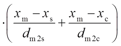
为了解决该问题,研究者提出双目视觉(图1(b))方法,利用两个相机中反射光线的交点可以确定反射点的位置[3]。但是该方法只能计算两个相机图像的重合部分,严重限制了对复杂曲面的成像范围,而且也增加了系统标定的复杂度。有研究者提出移动屏幕(图1(c))或者利用透射-反射双屏幕的方法[4-5],通过所采集图像的变化确定入射光线的方向。但是由于导轨的直线度误差、分光镜的折射等因素,会引入额外的测量误差。为此,亚利桑那大学的研究人员提出了SCOTS测量方法[6],如图1(d)所示。提供待测表面的名义面形,给定其基准位置,将反射光线与该表面的交点作为反射点,并将交点与对应屏幕像素的连线作为入射光线,基于反射定律计算反射光线和入射光线之间的角平分线,将其作为待测表面的法向,由此得到表面沿、方向的梯度:

图1 屏幕-相机像素对应关系。(a) 高度-斜率歧义性;(b) 双目偏折术;(c) 屏幕移动;(d) SCOTS


2 在位偏折测量的几何自标定
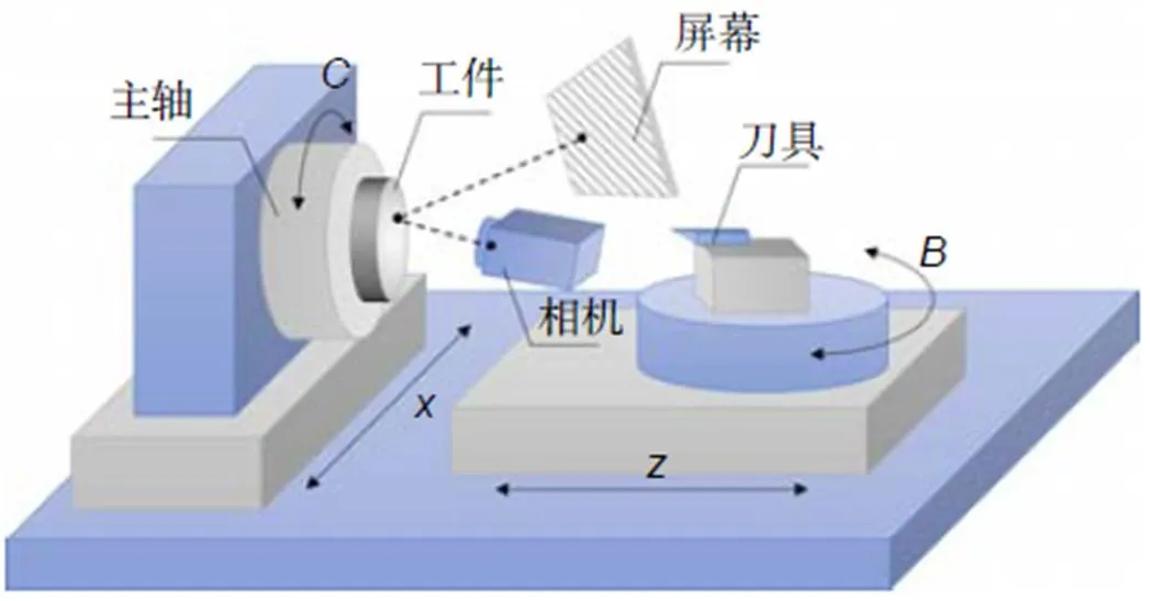
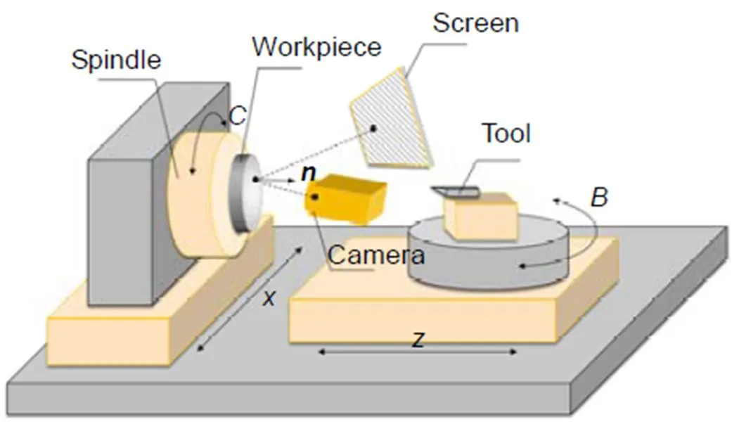
单点金刚石切削是当前超精密光学曲面最重要的加工方法。根据五轴单点金刚石切削机床的结构特点设计了在位偏折测量系统,如图2所示[7]。
测量系统中的屏幕和相机固定在刀座所在的B轴上,可以根据需要调整姿态,使得屏幕图样经过被测元件反射后成像在相机内,但在测量过程中保持位置固定。由于被测表面的面形复杂性,相机难以完整地获取整个表面反射的条纹图样。因此,可以使测量系统只对被测元件的部分区域成像,并通过转动机床主轴带着工件移动,实现不同局部区域的测量。由于测量系统中屏幕和相机的位置直接影响式(1)~式(2)中角平分线的计算结果,因此需要确定各部件之间的相对位置。当前一般采用三坐标测量机或者激光追踪仪等仪器探测被测表面的顶点、焦点等特征点对工件进行定位,而在后续重构过程中保持该基准位置不变[8]。但是在位测量系统中,由于机床空间以及环境干扰等因素的限制,难以引入额外的计量仪器来进行几何标定。

在图2的离轴光路条件下,反射镜面沿方向平移和绕轴倾斜都会导致追迹点位置沿方向偏移。也就是说,这两个位置变量之间存在耦合关系,需要提供额外的约束才能使得定位问题在数值上适定。由于反射镜的安装偏差,其法向不能和主轴完全重合,因此主轴带动反射镜转动一定角度,如π/2,则相机所拍摄的图像会发生偏移,两个姿态下的投影偏差可以将不同误差变量进行有效解耦。将两个位置下屏幕标志点在相机中的实际像素坐标作为已知量,将所有像素的追迹偏差平方和作为目标函数进行数值优化,具体流程如图4所示:首先进行相机标定,然后将标定板固定在主轴卡盘上,相机直接对其成像,利用视觉方法即可确定世界坐标系与相机之间的关系。再将参考反射镜固定在卡盘上,转动主轴得到两个位姿,利用光线追迹进行参数优化直至收敛,便可得到相机、屏幕、反射镜以及主轴之间的相对位置。

图2 单点金刚石车床的原位偏折测量系统

图3 几何自标定的坐标系

图4 几何自标定方法的流程图
由于变量数目较多,将其同步优化容易导致系统在数值上不稳定。因此将变量分为、、三组,分组依据组内变量强相关、组间变量弱耦合的原则进行:


3 被测元件高度的迭代计算
上面的几何标定采用参考反射镜来确定相机和屏幕相对于世界坐标系的位置。而世界坐标系的轴是通过主轴带动标定板转动来确定的,因此坐标系的轴方向和机床坐标系能够较好地匹配。而世界坐标系的轴原点建立在卡盘工作面上,用来辅助几何定位的标定板和参考反射镜的厚度难以准确得到。而且,实际加工过程中,对刀精度较差,误差可达亚毫米级,也会导致世界坐标系和机床坐标系之间存在方向的平移偏差,从而影响实际测量的可靠性。
在传统的SCOTS方法中,工件的名义模型只用来和反射光线相交计算反射点的位置。将该点处反射光线与入射光线的角平分线赋予表面法向,积分得到测量面形,而在迭代计算过程中保持名义表面的位置不变。因此这是一个从名义模型的高度得到测量面形的单向映射问题,工件的位置需要采用第三方精密仪器探测而确定。而在单点金刚石切削加工中,实际面形和名义面形之间的偏差都在微米级以内。更重要的是,在最小二乘意义下,面形偏差必然对称分布在名义面形两侧,如图5所示。

图5 多个像素的追迹偏差。(a) 高度误差引起的偏差;(b) 面形误差引起的偏差
若从相机像素进行逆向光线追迹,经名义面形反射后与屏幕平面相交,可得与实际对应像素的偏差。由于偏折测量系统为离轴光路,工件沿方向的偏移会导致追迹像素单向偏移;而两侧分布的面形偏差会导致追迹像素沿不同方向偏摆[12]。因此,可根据追迹偏差的统计特性来分离工件的位置误差与面形误差。我们将整个迭代计算过程分为高度子问题与面形子问题,二者交替进行,如图6所示。
在高度子问题中,以工件的实际高度为变量,以所有光线的追迹偏差的平方和为目标函数进行优化,如图7所示。而在面形子问题中,除了首次预估反射点可以由过相机光心的反射光线与名义面形直接计算而得,后续迭代中的反射点需要用反射光线和当前重构的面形计算。然而,重构的面形不再是连续的面形方程,而是离散点的集合。通过Delaunay三角化,离散点可构建为三角面片的集合[13]。因此后续迭代中的反射点可由反射光线与三角面片相交得到,如图8所示。
该优化方法充分利用了被测面形的信息,其位置用于计算反射点,而其法向用来进行光线追迹,通过追迹偏差的统计特性来分离位置误差和面形偏差。于是,传统的单向映射问题就转变为位置-面形双向映射问题。
4 自由曲面子孔径的准确定位
对于复杂的自由曲面,由于偏折测量中成像范围的限制,通常难以单次覆盖全口径,需要通过子孔径拼接来完成整个工件的测量。但是子孔径测量对应中的工件区域难以准确定位,即使对同一个名义模型,不同区域所对应的表面位姿及名义面形都不一样,给后续的测量重构及质量评定带来很大的困难。
每个子孔径位姿在空间中有六个运动自由度,分别为t, t, t,θ,θ, θ。其中θ对相机所采集的条纹图样的影响和具体的被测面形有关,而且一般是非敏感量,暂时不作深入讨论。t在上一节中已开展分析,它会导致追迹像素沿某一方向偏斜。而另外四个运动自由度对投影偏差的影响都有特定规律。由于每个投影点都有、两个坐标分量,也即通过光线追迹可以得到两个方程,而对于t, t, t,θ,θ五个自由度至少需要三个姿态才能提供足够的约束条件,使得子孔径定位问题适定。因此利用气浮转台,分别转动0°、90°、180°,所对应的三个姿态分别称为、、,则在屏幕的像素坐标系中,各个自由度所对应的投影偏差方向如表1所示。

图6 在位测量的迭代策略流程图

图7 高度子问题

图8 面形子问题

表1 工件位姿误差对投影偏差的影响
对同一个相机像素,在三个姿态下对同一变量的偏差可写成6元向量形式。只要表1中的偏差量不为零,则五个运动自由度构成的六维向量必然线性无关,也即三个姿态下的投影偏差能够使得系统适定。我们对某一子孔径从相机像素到屏幕进行反向光线追迹,假定一共有对反向追迹像素,则可以构建目标函数:

值得一提的是,在优化定位问题中,每次工件位置发生调整,则会导致光线与名义表面的交点改变,即反射点需要重新计算,导致求导计算非常复杂。因此这里采用粒子群优化(particle swarm optimization,PSO)算法,通过模拟鸟群在觅食过程中个体和群体之间的信息交换方式而寻找最优目标解[14-15],可以避免求导运算。以三个位姿下追迹偏差的平方和作为PSO的适应度。这里特别说明的是,PSO的寻优能力和初始粒子是否遍布搜索空间内有关。通常使用伪随机数生成初始粒子,然而随机数很多时候不能均匀地覆盖整个空间,尤其是当搜索空间维度较高的时候,如图9(a)所示。因此在PSO求解定位模型时,引入Hammersley序列[16]生成均匀的初始粒子,以避免陷入局部最优,如图9(b)所示。
设搜索空间是维的,个粒子在空间中的坐标={|=1,…,}由上述Hammersley初始化。第代的粒子速度(即粒子的坐标变化)可记为

其中:k>1,c1和c2为加速系数,用以调节粒子朝向当前解pi和本代中的全局解pg的相对速度。r1和r2为D维的[0, 1]随机数,Ä是点乘运算,χ是提升稳定性的收缩因子。这里取c1=c2=2.05,χ=0.7298[17]。PSO求解定位的流程如图10所示。

图10 PSO求解被测工件的定位流程图
5 实验结果
首先利用球面反射镜进行验证,型号为Edmund#40-913,如图11所示。该球面反射镜的名义口径为127 mm,名义曲率半径为1270 mm。该工件使用4D PhaseCam 6000型动态干涉仪进行测量,如图12所示。经单目偏折术测量后,使用Modal法重构的面形如图13(a)所示。与干涉仪的结果之差则如图13(b)所示,单目偏折术测量与干涉仪测量差异的RMS为31.34 nm,PV为189.75 nm。实验证明,当测量球面时,本文提出的单目偏折术的测量精度与干涉仪相当。
抛物面镜广泛地应用于光学系统中的光束准直。而在卡塞格林望远镜这一类需要转折光路的应用场景中,主镜需要留出通孔,避免光束遮挡。这里采用Precitech Freeform XL单点金刚石车床加工了一个中空离轴抛物镜(off-axis parabolic, OAP),如图14所示,其名义指标如表2所示。因为这一类型的光学表面不具有几何中心点和极值点,且其边缘点不可探测,也即没有可用的几何特征点,因此中空离轴抛物面镜无法用传统的SCOTS方法测量。采用本文所提出的几何标定与定位方法进行偏折测量,实际被测的子孔径区域以及所拍摄的条纹如图15所示,绿色虚线内为被测子孔径。为了进行对比验证,使用Zygo GPI XP/D型干涉仪结合标准球进行零位测量。由于需要在光路中同时调整被测镜面和标准球的位姿,因此干涉测量非常耗时。

图11 球面反射镜

图12 球面镜的干涉仪测量

图13 球面镜的测量结果。(a) Modal重构;(b) 与干涉仪测量之差

图14 中空离轴抛物面镜

表2 中空离轴抛物镜的技术指标

图15 中空离轴抛物面镜的横纵变形条纹。(a) 纵向; (b) 横向
被测中央通孔抛物面镜的面形经过4次迭代计算获得,减去拟合的理想抛物面后,去除与面形位置有关的Zernike前四项(分别代表平移、倾斜以及离焦),与干涉仪结果作对比,如图16所示。相对于干涉测量结果,在位单目子孔径测量差异的RMS为139.85 nm,PV为682.89 nm。使用低阶Zernike多项式(5到11)分析各项的贡献,列于表3中。可见由测量系统离轴配置而引起的像散贡献最大[18]。实验证明,本文提出的在位偏折测量能够实现中空离轴抛物面镜的非零位快速测量,提高了测量效率。

图16 中空离轴抛物面镜测量结果。(a) 单目偏折测量结果;(b) 干涉仪测量结果;(c) 两者差异

表3 各像差项对相对差异RMS的贡献度
6 结 论
偏折测量技术的抗环境干扰能力强、结构简单、通用性好,尤其适用于精密光学加工的在位测量。其测量精度取决于所计算的角平分线和实际表面法向的匹配程度。因此,引起测量误差的因素包括相机、屏幕、工件之间的相对位置、系统像差导致的像点相位失配、反射光线不通过相机光心引起的偏差等。其中几何位置的准确性是决定测量精度的主要因素。传统偏折术采用第三方仪器探测特征点来决定工件位置,难以用于实际精密加工的在位测量。本文以光线追迹为工具,分析了不同条件下位姿求解问题的适定性,以及追迹误差相对于各误差因素的敏感性及其统计规律。据此有效分离各项误差,仅利用机床自身的运动轴系即可完成偏折测量系统中各部件的精准定位,显著提高了测量效率与可靠性,降低了精密制造的成本与复杂性。因此,所发展的精密测量技术对提高我国精密光学制造的技术水平有重要意义。
[1] Huang L, Idir M, Zuo C,. Review of phase measuring deflectometry[J].2018, 107: 247–257.
[2] Niu Z Q, Xu X Y, Zhang X C,. Efficient phase retrieval of two-dimensional phase-shifting fringe patterns using geometric constraints of deflectometry[J].2019, 27(6): 8195–8207.
[3] Xu Y J, Gao F, Jiang X Q. Enhancement of measurement accuracy of optical stereo deflectometry based on imaging model analysis[J].2018, 111: 1–7.
[4] Xiao Y L, Su X Y, Chen W J,. Three-dimensional shape measurement of aspheric mirrors with fringe reflection photogrammetry[J]., 2012, 51(4): 457–464.
[5] Liu Y, Huang S J, Zhang Z H,. Full-field 3D shape measurement of discontinuous specular objects by direct phase measuring deflectometry[J]., 2017, 7(1): 10293.
[6] Su P, Wang Y H, Burge J H,. Non-null full field X-ray mirror metrology using SCOTS: a reflection deflectometry approach[J]., 2012, 20(11): 12393–12406.
[7] Zhang X C, Xu X Y, Niu Z Q,. Precise positioning in the in-situ deflectometric measurement of optical surfaces[J]., 2019, 11102: 111020S.
[8] Graves L R, Choi H, Zhao W C,. Model-free deflectometry for freeform optics measurement using an iterative reconstruction technique[J]., 2018, 43(9): 2110–2113.
[9] Zhang Z Y. A flexible new technique for camera calibration[J]., 2000, 22(11): 1330–1334.
[10] Xu X Y, Zhang X C, Niu Z Q,. Self-calibration ofmonoscopic deflectometric measurement in precision optical manufacturing[J]., 2019, 27(5): 7523–7536.
[11] Li S Q, Xu C, Xie M. A robust() solution to the perspective-n-point problem[J]., 2012, 34(7): 1444–1450.
[12] Xu X Y, Zhang X C, Niu Z Q,. Extra-detection-free monoscopic deflectometry for themeasurement of freeform specular surfaces[J]., 2019, 44(17): 4271–4274.
[13] O’Rourker J.[M]. 2nd ed. Cambridge: Cambridge University Press, 1994.
[14] Kennedy J. Particle swarm optimization[M]//Sam-mut C, Webb G I.Boston, MA: Springer, 2010: 760–766.
[15] Zhang X C, Jiang X Q, Scott P J. A reliable method of minimum zone evaluation of cylindricity and conicity from coordinate measurement data[J]., 2011, 35(3): 484–489.
[16] Wong T T, Luk W S, Heng P A. Sampling with hammersley and halton points[J]., 1997, 2(2): 9–24.
[17] Clerc M, Kennedy J. The particle swarm-explosion, stability, and convergence in a multidimensional complex space[J]., 2002, 6(1): 58–73.
[18] Huang R, Su P, Horne T,. Optical metrology of a large deformable aspherical mirror using software configurable optical test system[J]., 2014, 53(8): 085106.
In-situ deflectometric measurement of optical surfaces for precision manufacturing
Zhang Xiangchao*, Xu Min
Shanghai Engineering Research Centre of Ultra-Precision Optical Manufacturing, Fudan University, Shanghai 200438, China

In-situ deflectometric measuring system
Overview:In recent years, the measurement of freeform optical surfaces has attracted intensive attention in precision engineering. Off-line measurement using laboratory instruments causes remounting errors and low manufacturing efficiency, thus high precision in-situ measurement technologies are required. The phase measuring deflectometry is a powerful measuring technique for complex specular surfaces. Its measurement accuracy is comparable with conventional interferometry, but with higher flexibility, stability and dynamic range.
In this paper, an in-situ deflectometric measurement method is developed for the ultra-precision optical manufacturing with single point diamond turning. The measuring accuracy of deflectometry depends on the reliability of the geometrical positions between the camera, screen and workpiece, but it is difficult to conduct precise geometrical calibration using a third-party instrument in the situation of the in-situ measurement.
A self-calibration method is proposed to determine the positions of the camera and the screen. A world coordinate system is established by introducing a flat mirror without markers, rather than using high-precision metrological instruments. The rays are re-traced from the screen to the camera, and numerical optimization is performed on the global parameters, including the camera intrinsic parameters, the screen intrinsic parameters and the geometric transformations by minimizing sum of the squared tracing deviations. Only four images need to be captured, hereby reducing the operating complexity and improving the measuring efficiency.
The behaviors of the position error and form error of the measured surface can be discriminated according to the statistical properties of the tracing deviations, and the axial position of the workpiece can be determined accordingly. By fully utilizing the nominal model, the conventional one-way position-form mapping is converted into a two-way mapping problem. Extra detections can in turn be avoided, and the measuring efficiency and range of freeform surfaces can be greatly improved. The whole aperture cannot be measured simultaneously due to the limit of the imaging scope of the camera used. A positioning method is proposed to specify the pose/location of the measured sub-aperture surface. Reverse ray-tracing from the camera to the screen via the measured surface is conducted, and a rotary stage carrying the workpiece is rotated to provide external constraints. The particle swarm optimization method is adopted to solve this problem.
Several typical optical surfaces including an off-axis paraboloid mirror are measured using the proposed deflectometric measuring method. Experimental results demonstrate that the measurement error is within 150 nm. The superior performance prove that this method is of significance for the technical development of ultra-precision intelligent manufacturing.
Citation: Zhang X C, Xu MIn-situ deflectometric measurement of optical surfaces for precision manufacturing[J]., 2020, 47(8): 190581
In-situ deflectometric measurement of optical surfaces for precision manufacturing
Zhang Xiangchao*, Xu Min
Shanghai Engineering Research Centre of Ultra-Precision Optical Manufacturing, Fudan University, Shanghai 200438, China
The in-situ measurement of complex optical surfaces is a challenging task in precision engineering. The phase measuring deflectometry is a powerful measuring method for complex specular surfaces, and it has higher measuring efficiency, stability and dynamic range compared to interferometry. Consequently it is promising to widespread applications in various fields. Deflectometry is essentially a calibration problem, and the measuring accuracy is directly determined by the quality of geometrical calibration. An in-situ deflectometric measuring system is designed based on the single point diamond turning machine. A self-calibration method is developed to specify the relative positions of the camera and screen. Ray tracing is conducted at two positions of an auxiliary reflecting mirror, which is mounted on an air bearing spindle. The accuracy of the geometrical positions can be improved by an order of magnitude by minimizing the deviations of the traced points with respect to the true correspondences. According to the statistical properties of the deviations in reverse ray tracing, the form errors and the position errors can be separated, and the positioning error of the workpiece can be corrected accordingly. Henceforth, the nominal shape of the fabricated workpiece can be fully utilized, and the conventional one-way position-form mapping can be converted into a two-way mapping problem. As for the complex shapes, the whole surface can be covered by sub-aperture measurement. Precise localization of a local region under test is achieved by multi-position imaging, so that correct convergence of the iterative reconstruction process can be guaranteed. Several typical optical surfaces including an off-axis paraboloid mirror are measured, and the measuring accuracy of the proposed method is proved better than 150 nm RMS.
optical manufacturing; in-situ measurement; deflectometry; geometrical calibration; ray tracing
TH741;TH247
A
10.12086/oee.2020.190581
: Zhang X C, Xu M. In-situ deflectometric measurement of optical surfaces for precision manufacturing[J]., 2020,47(8): 190581
张祥朝,徐敏. 面向精密制造的光学自由曲面在位偏折测量技术[J]. 光电工程,2020,47(8): 190581
Supported by National Natural Science Foundation of China (51875107) and Science Challenging Program (JCKY2016212A506-0106)
* E-mail: zxchao@fudan.edu.cn
2019-09-20;
2019-11-19
国家自然科学基金资助项目(51875107);国防基础科研科学挑战专题(JCKY2016212A506-0106)
张祥朝(1982-),男,博士,副研究员,主要从事在线检测与表面计量学的研究。E-mail:zxchao@fudan.edu.cn
