Evacuation lighting technology for buildings using piezoelectric sensors sheets
2020-06-30MujeebAliKHANSONGWeiguo
Mujeeb Ali KHAN, SONG Weiguo
(State Key Laboratory of Fire Science, University of Science and Technology of China, Hefei 230026, China)
Abstract:Safety, power, and energy are the basic requirements in the modern era. The ultimate solution is to implement renewable energy sources to deal with the growing desire for power and then utilize it for human safety. It is required to use these sorts of renewable energy in the right way. In this paper, we studied footsteps for power generation from piezoelectric sensor sheets. For illustration, how to use that energy for the evacuation lighting of the buildings, we fixed the moveable net bolts below and top of the sensors with wood sheets to generate electrical power from footsteps using a piezoelectric sensors system. Also, we put silicone gel on top of all sensors located on the lower wood plate, and then impulsive pressure is applied when somebody takes a step on wooden sheets. A hole is fixed at the bottom and on the top of wood sheets to adjust moveable net bolts among the plates. A smoke sensor was used to initiate the lights. Using this equipment, in the evacuation path of the buildings, we can run LEDs or lights. It has revealed that these types of approaches and designs of electrical power generation have specific values for safety purposes, and generally to encounter the amount and requirements of energy.
Keywords: Piezoelectric sensor; Evacuation lighting; Power generation; Footsteps; Renewable energy
1 Introduction
In all the features of life, energy surrounds us, and it entirely depends on us whether to use it in an undesirable manner or the desired method. These energy sources are not from fossil fuels or atom distribution, but these alternate energy resources are Nuclear energy, Wind power[1], Geothermal, Hydroelectric, and solar energy. On the other hand, we face a big problem in building evacuation, such as human accidents or natural disasters. We have different types of building evacuation, such as vertical evacuation, horizontal evacuation, and stay in place, etc.
For reducing the evacuation time in buildings and eliminate human loss in natural and human disasters, we presented a new method to minimize energy demand and evacuation time in buildings. We used human power[2]and utilized that energy to evacuate the building through piezoelectric sensors sheets using LEDs.
To generate power and evacuation of the buildings through footsteps, we have various types of resources[3]to produce that energy and for the evacuation of buildings, but the process used in this study is electrical generation from the footsteps using piezoelectric sensors. As we know that this is a different approach, and this technology used to generate electrical energy is often used in developed countries and is currently under examination.
1.1 Overview of renewable energy sources
The world is paying more attention to renewable energy resources due to global warming. The power generation resources are too expensive[4]throughout the world, and raw materials are not enough to produce the required energy. To maintain current resources, we needed heavy equipment, lots of money, and labor. Apart from this, there are many other shortcomings of these renewable resource organizations. A nuclear generator can cause the worst cancer disease by radiation, and hydroelectric power projects can cause floods. As a result of the problems caused due to these energy sources, people are moving to renewable and inexpensive energy sources, which are efficient and useful, and friendly to people[5]without risk to humans. Renewable resources such as wind turbines, solar panels, geothermal, and biogas for power generation are all used and are natural, and it does not harm the environment. Also, these companies are inexpensive. These types of power plants do not need heavy equipment. So, whenever a huge problem arises with these plants or they stop working, they do not need a costly repair. It is based on engineering techniques and does not require heavy machinery, so it does not need any labor effort. Therefore this study was based on renewable energy sources and how we can use that energy to evacuate buildings and to generate electricity more efficiently and economically. Although this technique we have proposed is too cheap, there is no need to use heavy equipment due to the convenience for maintenance, while generating energy continuously in an ordinary and emergency. This system does not require other resources; it only needs human measures for energy generation. There is only a one-time cost to implement the system and to generate free energy.
1.2 Power generation from footsteps resources
We have many other resources, but in this study, we choose to generate energy from piezoelectric sensors through human steps[6]. This unique method is currently being tested as energy generation technology and used in developed countries. This type of power generation could be achieved using various methods such as springs and pedal arrangements, piezoelectric sensors, fly and gear wheel-mechanical arrangements, stair power generating systems by rotating generators, and Faraday Electromagnetic Induction Law[7].
We propose our research based on piezoelectric sensors and a wood-like assembly. The wood assembly we designed consists of 4 wooden sheets, and each wood sheet consists of 18 piezoelectric sensors, which were in series and parallel connection. Net bolts fixed between the sensor plates were strong enough to resist the force of the person. The above-suggested method could be installed and then applied in tall and small buildings, railway stations, bus stations, airports, schools, universities, markets, footpaths, crowded areas, and areas where there are many pedestrians.
2 Working principle
Few steps in the principles of this prototype design are regarding the generation of electrical power from piezoelectric sensors by using the footsteps of human beings and how to use that energy for evacuation lighting of the building.
In this prototype design, to convert mechanical energy into electrical energy[8], the process starts with the proper assembly of electrical components, such as sensors and batteries, and mechanical equipment, such as net bolts and sheets. For the vibration of sensors, we need net bolt assembly for these sensors, and by applying force on the sheets, the mechanical energy converts into electrical energy. When on the sheets, we put mechanical energy, net bolts provide vibration to the piezoelectric sensors, and electrical power generated was stored in batteries[9]. The load connected to the batteries consumes this electric power.
The piezoelectric sensors generate A/C voltages. Therefore, to store electric energy produced by these sensors in the batteries, we need conversion from A/C voltages to D/C voltages. For the conversion of A/C voltages into D/C voltages, we used rectifiers. There are two kinds of rectifiers, one a half-wave rectifier, and the other is a full-bridge wave rectifier. In this prototype design, we used a full-bridge wave rectifier to get full wave A/C voltages. We store converted D/C voltages in a 12-volt battery.
Our main requirement was to operate D/C loads, which are LEDs or bulbs in this system. However, the appliances used in schools, homes, offices, train stations, universities, airports, and other public places are AC power, so we can use an inverter to convert these D/C voltages into A/C voltages. This inverter should convert DC 12 volts into AC 220 volts[10], utilized for charging various electrical tools such as laptops, mobile phones, and lighting streets.
The correlation between piezoelectric sensors with power generations is entirely direct, meaning that power generation to piezoelectric sensors is directly proportional. If we increase the number of sensors, we can acquire more energy. Whenever we need more electrical power, we need to increase the number of sensors. The batteries designed must produce high voltages and currents to increase the capacity of batteries and inverters. However, for this conversion, the inverter should have the ability not to lose any charges. If we utilize such a battery and an inverter, more electric power would be backed up and it can supply more appliances. However, in our prototype design, our main objective was to operate LEDs[11]or bulbs directly from D/C power to lighten the paths in the buildings for evacuation.
3 Description of the components
3.1 Piezoelectric sensor
A piezoelectric sensor utilizes its piezoelectric effects to measure the difference in acceleration pressure, strain, or force by first changing them to electric power. Piezoelectric sensors (Fig.1) can be used in industries to measure several processes. The industrial use of piezoelectric sensors was introduced in the 1950s as a process control, research development, and quality assurance tool and has proven the most flexible and highly reliable technology. Technologies like medicine, telephones, pressure sensors, aerospace, and nuclear side, the use of piezoelectric sensors have been successful. It can take over the automotive industry quickly, detecting heat while internal engines are on fire.
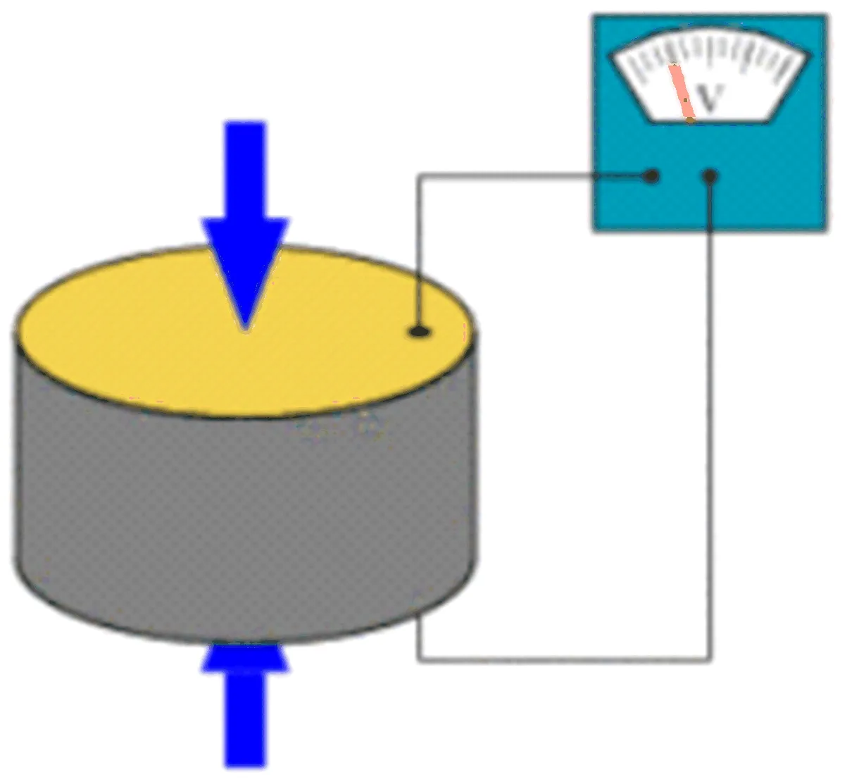
图1 压电圆盘
Due to its electro-compatible properties, the utilization of piezoelectric technology has increased. The advantages of the feature, such as the high modulus of piezoelectric material elasticity, are equivalent to most metals and shoot up to 10e6N/m2. The use of piezoelectric sensors even in extreme conditions and resistance to electrical and light fields is due to the property such as durability, which results in line extraction, and the natural operating frequency of various amplitude types, which provide measurements. Materials like Gallium, Phosphate, and Tourmaline with high durability and high temporal coefficient increase the ability of sensors to function even when the temperature[13]reaches thousands of degrees centigrade. Furthermore, when the Tourmaline temperature is different from that of piezoelectric material, Tourmaline provides pyro-electricity; Tourmaline releases an electrical signal found in objects like ceramics.
There are advantages and also disadvantages with piezoelectric sensors. The piezoelectric sensors do not work for statistical instability[14]. The piezoelectric sensors generate weak signals through the loss of electrons by using static power; produce only a fixed number of charges.
Due to twin formation and a further decrease in internal resistivity and increased sensitivity to pressure and high temperatures can interfere with piezoelectric effects[15]. Alternatively, quartz nerves have the advantage of not showing twin formation above 300 degrees centigrade, which is needed to be cooled by precise crystals, for example, gallium phosphate (GaPO4).
3.2 Rectifier
A device capable of converting A/C voltages into D/C voltages is known as a rectifier[16]. The rectifier can convert a half-wave or full-wave A/C source into a D/C source. In our study, we get full-wave rectification and stability through four diodes full-wave bridge rectifier. The D/C source converted through the full-wave bridge rectifier is utilized by our load.
3.3 Unidirectional current controller
The devices that allow the current to pass only through one direction are the unidirectional current controller. There are many devices like this, but in our study, we have used the following.
· Diode
· Thyristors
In our study, the diode operates as the unidirectional current controller. The diode helps the flow of current in the forward direction and eliminates the reverse current[17]. We have used the D=1N4007 diode for this purpose.
3.4 Smoke detector
The MQ-2 gas sensor has an electrochemical detector[18], which alters its resistance to different concentrations of combustion. The sensitivity of the electrochemical detector changes with a voltage divider. The voltage divider consists of a variable resistor connected in series with a sensor. The resistance of the detector changes with gaseous material released from contact with the detector after heating. The detector changes the voltage all over the sensor, and the microcontroller reads the voltage. The voltage value finds the sensor resistance by knowing the reference voltage and resistance of another resistor. The detector shows different sensitivity for different types of gasses.
3.5 ARDUINO
ARDUINO is an innovation of electronics because of its speedy processing and ease of use. It is an open-source physical opening section based on the MC board and editing background. New electronic devices and smart systems use ARDUINO[19]. ARDUINO services may remain anonymous, or they may be able to run the code that works on your PC. The language used in designing the ARDUINO system is the practice of Wiring, which is an equal category of somatic speculation based on a variety of MPC Processing.
4 Methodology
4.1 Block diagram
The process of the whole prototype design has described in the given flow diagram (Fig. 2). The piezoelectric sensor generates AC voltages and cannot be stored directly in the battery. Therefore, full-wave bridge rectifiers have been connected to all piezoelectric sensors to change alternating current into direct current. So, the function of rectifiers is to convert alternating current into direct current. After that, we connect the diode for the unidirectional flow of current, connected to all full-wave bridge rectifiers. Thus, the generated energy power flowed in one direction stored in the battery. Here, our D/C loads are LEDs or bulbs, Arduino microcontrollers, etc. These D/C loads activate by coupling a battery to the power supply circuit. For the detection of smoke or fire, a smoke sensor has connected to the microcontroller. Once it senses smoke or fire, the smoke detector sends a signal to the microcontroller and the entire system start working.
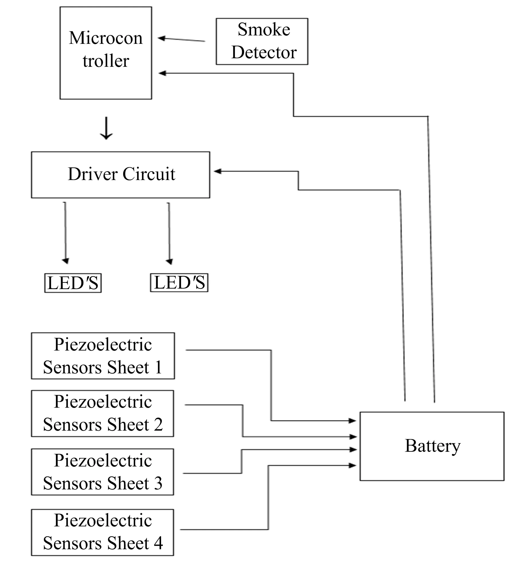
图2 流程图
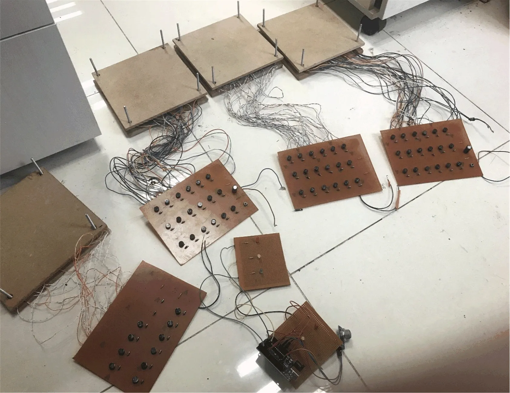
图3 硬件
4.2 Piezoelectric sensor sheet
Three main components (Fig. 3) used in the piezoelectric sensors sheets are:
· Diodes
· Piezoelectric sensors
· Rectifiers
4.2.1 Piezoelectric sensors
These sensors have two legs, and both legs are A/C. It produces A/C voltages.
4.2.2 Rectifiers
The piezoelectric sensors generate AC spikes and cannot be stored in the battery directly. The full-wave bridge rectifiers have been used in our prototype to convert these alternating (AC) spikes into (DC) voltages and store it in the battery. Altogether the rectifier has four pins. 2 legs of the rectifier are AC legs. One is positive, and the other is the negative leg.
4.2.3 Diodes
Diodes have two legs in total, one positive and the other negative. Diodes force the flow of current in the forward direction; block the flow in the backward direction to protect our circuitry.The main reason we used it in our research for the prototype design (Fig. 4).
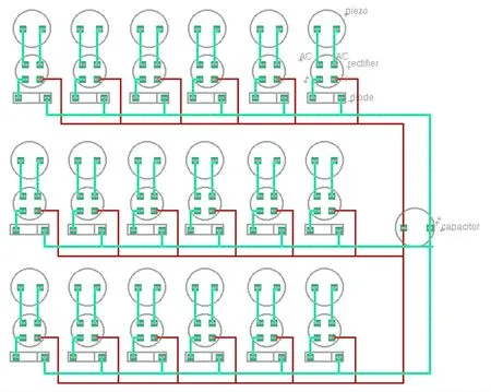
图4 压电传感板电路图
In this prototype design, a total of 18 piezoelectric sensors has used in one sheet. We have connected six sensors in series and three series combinations connected in parallel. As we discussed above, in the piezoelectric sensors, we can only get alternating (A/C) spikes, thus converting these alternating (A/C) spikes into direct (D/C) voltages with the full-wave bridge rectifier connected with every piezoelectric sensor. In our research, we connected each piezoelectric sensor with a rectifier, and the rectifier connected with a diode for acquiring maximum power. To flow the current in the forward direction and avoiding the backward flow of current, each full-wave bridge rectifier utilizes a diode. Altogether, the piezoelectric sensor has two A/C legs. We joined one with the AC leg of the full-wave bridge rectifier and the other to the other AC leg of the full-wave bridge rectifier. The anode leg of the full-wave bridge rectifier connects to the positive terminal of the battery. The cathode leg of the full-wave bridge rectifier connects to the cathode leg of a diode. Lastly, the negative terminal of the battery connects to the anode leg of a diode.
4.3 Smoke sensor circuit
The MQ-2 detector has an electrochemical detector; unlike concentrations of wide-ranging gasses, this sensor alters its resistance. In a voltage divider circuit for the electrochemical detector, a variable resistor connects in series with the electrochemical detector and the regulating resistor to adjust the sensitivity (Fig. 5).
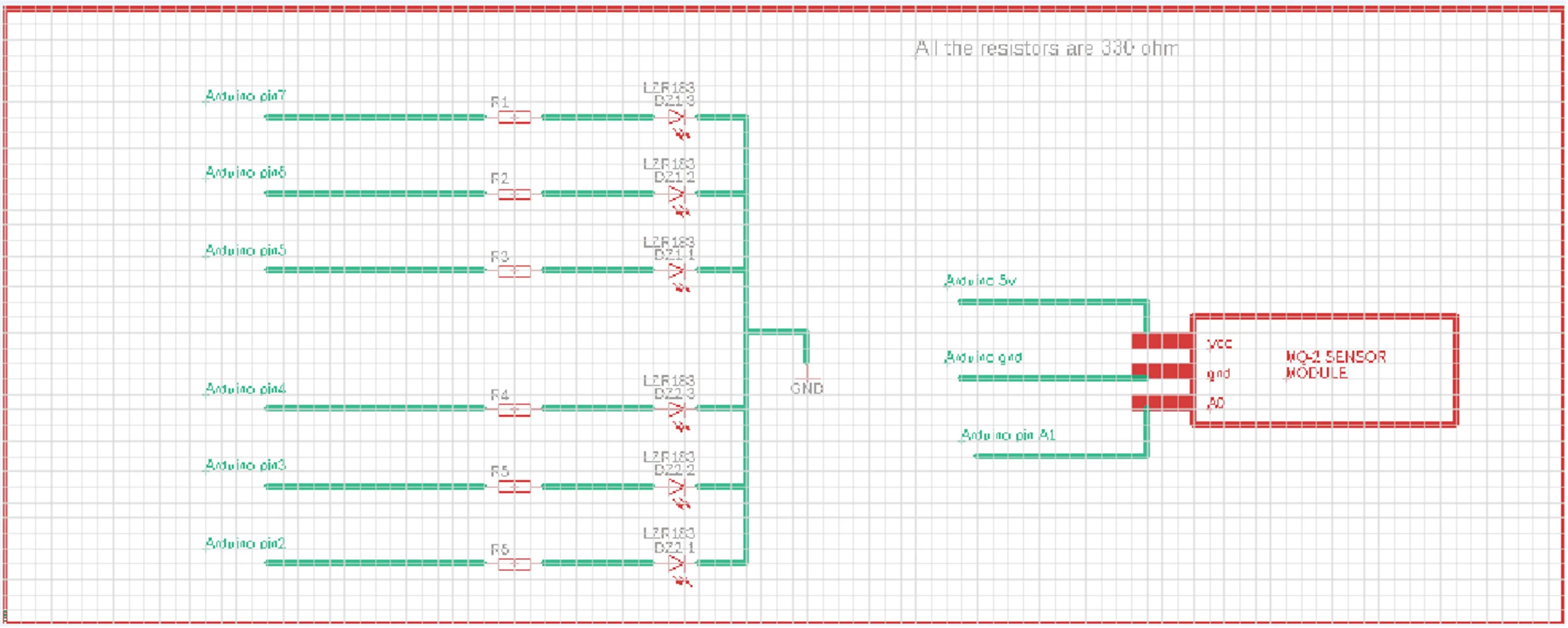
图5 烟雾探测器和LED电路图
In the above circuit diagram of a smoke sensor and LEDs, we used resistors, diodes, and a microcontroller. The anode of each diode connects to one terminal of each resistor. However, the cathode of each diode connects to the ground pin of the microcontroller. We connect another terminal of each resistor to the input pins of the microcontroller. The 5-volt pin of the microcontroller connects to the VCC pin of the smoke sensor. The ground pin connects to the ground, and the A1 pin connects with the A0 pin. The smoke sensor gives a signal to the microcontroller whenever it detects smoke or gas, and LEDs became turn ON and start blinking that lightens the path for people to see the ground, and shows the exit path to the people.
5 Maximum theoretical voltages generated
A charge is produced across piezoelectric sensors when force applies on piezoelectric sensors sheets. So, possibly it could be thought an ideal capacitor. For this reason, we apply all equations to this sensor leading to capacitors. In this prototype design, a total of 18 piezoelectric sensors has used in one sheet in which we have connected six sensors in series and three series combinations connected in parallel. Therefore, when four piezoelectric sensors sheets connected in series, its equivalent capacitance becomes:
(1)
As in this case,
Q=C×V
(2)
Wherefore,
(3)
So,
(4)
Thereupon,
Veq=V1+V2+V3+V4
(5)
Therefore, to get the net voltage produced, we should sum off single voltages produced from every piezoelectric sensor sheet connected in a series connection. From 1 piezoelectric sensors sheet, the average output voltage is 27 V.
Hence;
Veq=V1+V2+V3+V4
(6)
Veq= 27+27+27+27
(7)
Veq= 108 V
(8)
When the four piezoelectric sensors sheets connect in series, nearby 108 V is the max voltage generated.
6 Analysis done on the piezoelectric sensors sheets
We measure the voltage-producing capacity of the piezoelectric sensors sheets. When somebody takes steps on the piezoelectric sensors sheets, whose weight varies from 60 kg to 80 kg, the piezoelectric sensors produce electrical voltage. In Fig. 6, we plot the relationship between electrical power generated from one sheet and the varying weight. In Fig. 7, we observe that when max pressure, weight, or force applies to the sheet, the max voltage from one sheet is produced. Thus, when piezoelectric sensors sheets connect in series and when somebody whose weight various from 65 kg to 80 kg applies to the sheets, nearby 108 V is the max voltage generated (Fig. 8-Fig. 9).
In the given graph, we plot the power generated against weight from only one plate.
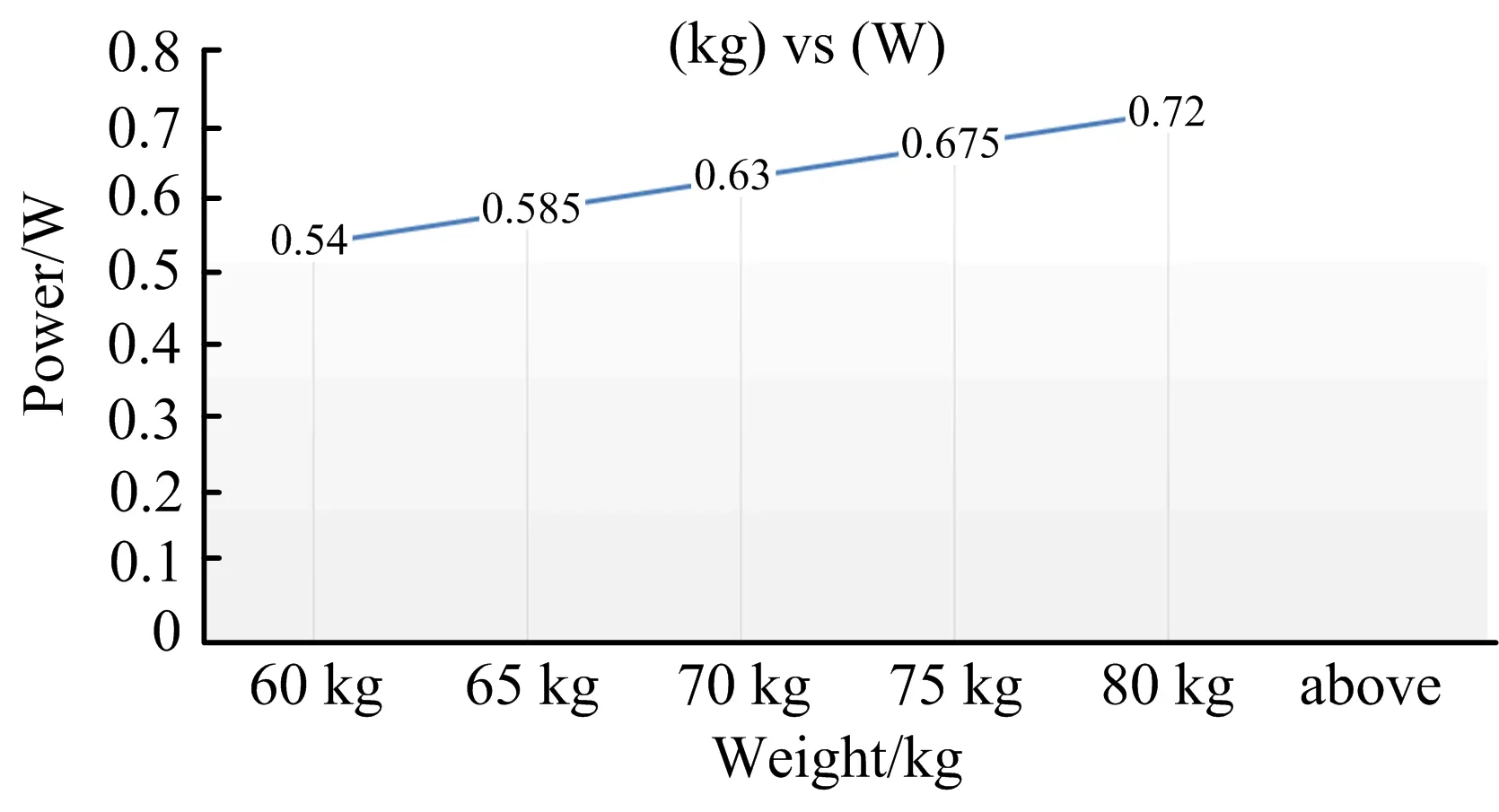
图6 重量和能量关系图
7 Result and calculations
The relationship between the power generated and pressure, the power generated is directly proportional to the pressure.
Now,
Pressure∝weight
(9)
P∝Wt.
(10)
When we takeKas a constant of proportionality, the equation becomes;
P=K×Wt.
(11)
As proportionality Constant=K, Weight=Wt. and Power=P
As we know that, from weightWt=60 kg, we can get the maximum value of current,I=0.020 A and voltage,V=27 V. Single push generates voltages up to 35 volts from one sheet. However, the power varies with the number of sensors pressed and force applied. Hence, we took 27 volts as an average voltage from one push and only one sheet.
Now,
Power=voltage×current
(12)
P=V×I
(13)
P=27 V×0.020 A
(14)
P=0.54 W
(15)
We can see that from the person with a weight of 60-kilogram power producedP=0.405 W. Hence generated power is directly proportional to pressure.
P=K×Wt.
(16)
K=P÷Wt.
(17)
K=0.54÷60
(18)
K=0.009
(19)
In the given graph, voltages generated for weight are shown only from Table 1.
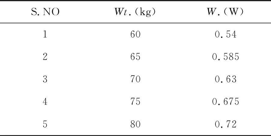
表1 能量和重量关系
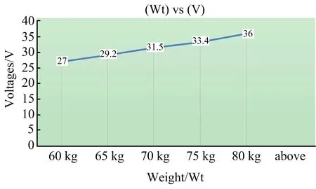
图7 重量和电压关系图
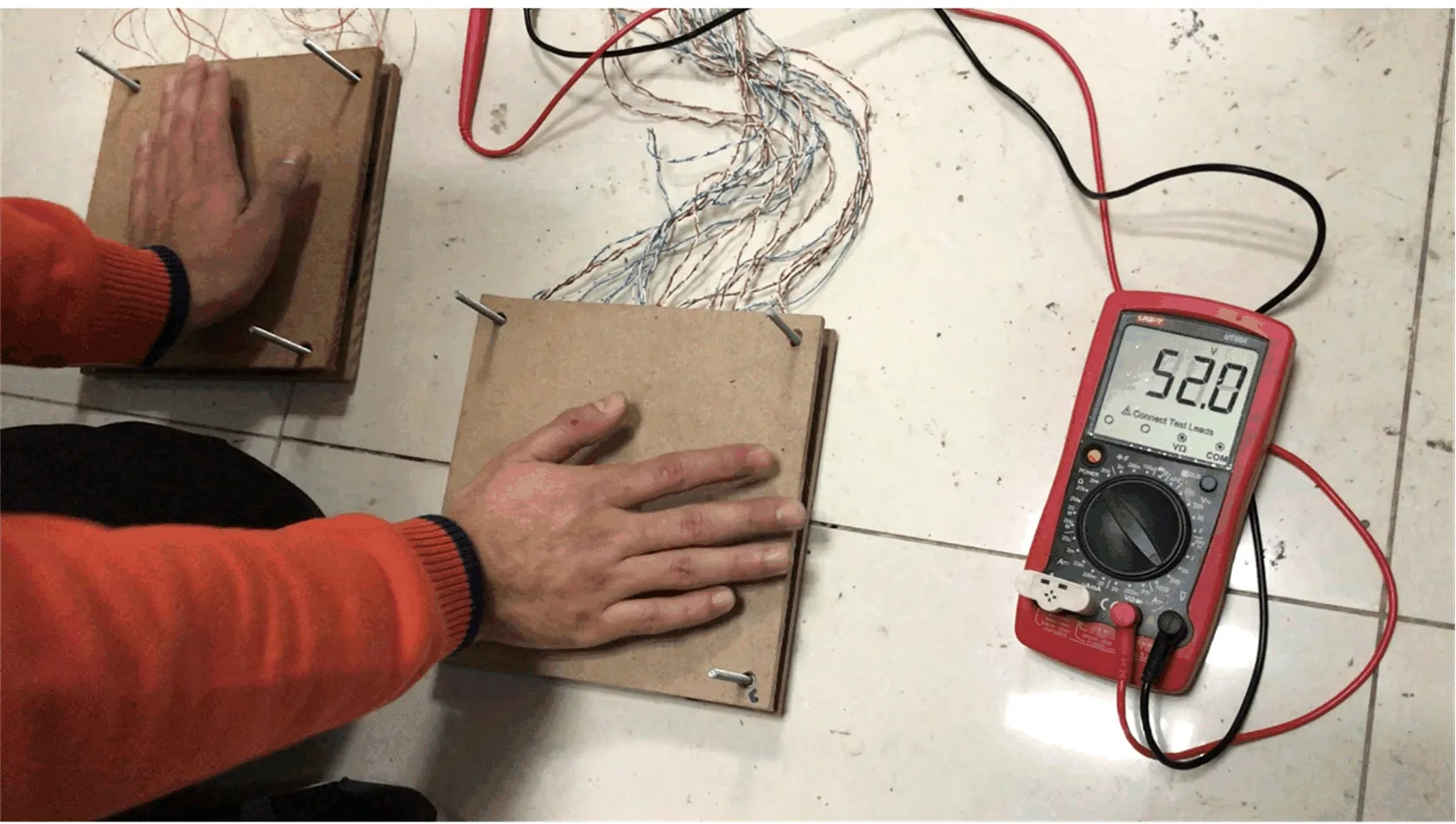
图8 两块板产生的电压

图9 三块板产生的电压
7.1 (Charging) of capacitor from piezoelectric sensors sheet and discharging by load
The motive of this experiment was to check either we can charge the battery or not. Therefore, a push button and a capacitor were placed in one piezoelectric sensors sheet whose value was 2 200 microfarads and voltage 6.3 V. Initially, when the capacitor discharges LED does not blink when we press the push button. When we started taking steps or start pushing the sheet, the capacitor starts charging. When we took 10~12 steps more after a few seconds, the capacitor charges, and then when we press the push button, the LED blinks till the capacitor discharges. The LED was glowing for a millisecond in this circuit. In Fig.10, we can see the output of the discharged capacitor. In Fig. 11, we can see the output from the charged capacitor.
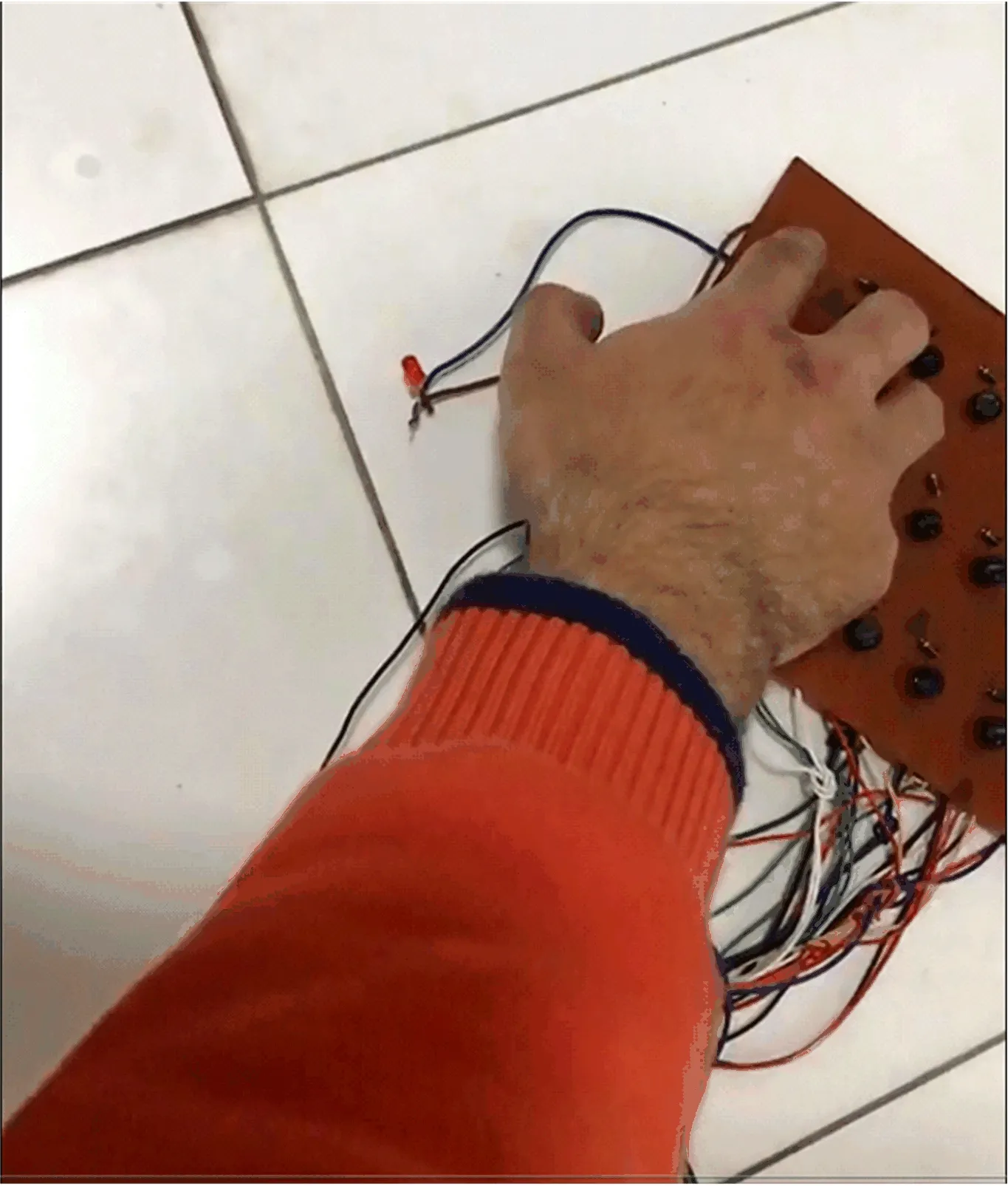
图10 未充电电容的输出

图11 充电电容的输出
Hence, this experiment proves that we can produce sufficient energy to store in the battery, and then we can consume that power in an efficient method.
7.2 Real-time function
From this experiment, we confirm the generated current and voltages from piezoelectric sensors sheets. In series connections, the current remains the same, and voltages added up. Therefore, in this experiment, nine LEDs were connected in series, and we check that either they can be turned on or not. The LED-rated forward current is 20 milliamp, and a typical forward voltage is 2.5 volts. All the nine LEDs were turned on and then turned off when we applied force on the piezoelectric sensors sheet. In Fig. 12, we can see the output without pressure applied on the sheet, while in Fig. 13, from the sheet with applied pressure.
The voltages added ups in series connections. Therefore, the equivalent LED forward voltages will become.
Veq=V1+V2+V3+V4+V5+
V6+V7+V8+V9
(20)
Veq= 2.5+2.5+2.5+2.5+2.5+
2.5+2.5+2.5+2.5
(21)
Veq= 22.5 V
(22)
And it is also known that the current remains the same in series connections that are 20 mA. Therefore, from the above experiment, we proved that the piezoelectric sensors sheets could generate the required currents and voltages.
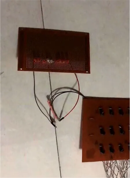
图12 未施加压力的输出
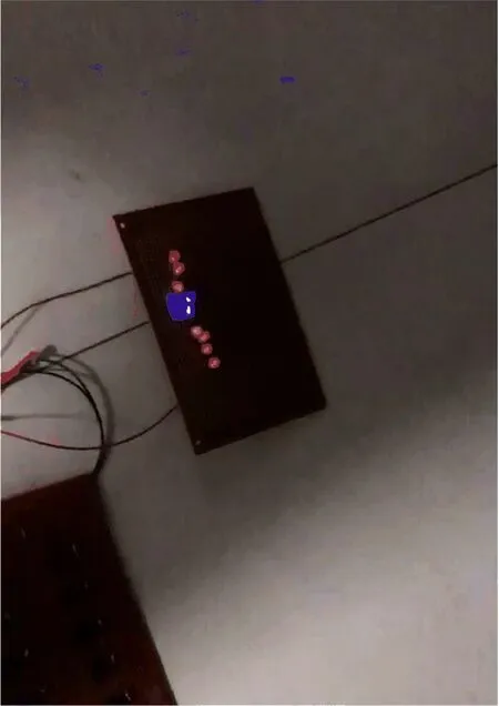
图13 施加压力的输出
7.3 Time required charging 12 V, 40 Ah battery
To get charging time, the time to charge the battery, the battery current is divided by the current applied.
From 1 sheet, we can acquire 0.020 Amp current. Therefore, by dividing the source battery current by the current applied, we get:
40 Ah÷0.020 A = 2 000 Hours approximately.
To charge 12 V and 40 Ah batteries, around 2 000 hours are required. If we convert hours into seconds, we will acquire the value of 7,200,000 seconds.
7.4 Implementing this system in our building
In the area of 33 by 33 feet (33 feet long and 33 feet wide), we implement this system in the main entrance door of the State Key Laboratory of Fire Science building. We make around 50 sheets of arrangement and use 900 piezoelectric sensors in these sheets. Connect the output of each piezoelectric sensors sheet in parallel, and we can acquire a current of 1 A.
In this case, the applied current will be 1 A, and we know that in parallel connections, the current adds up, and the voltage remains the same.
To get charging time, the time to charge the battery, the battery current is divided by the current applied.
· 40 Ah÷1 A = 40 Hours estimated.
Therefore, to charge our battery, approximately 40 hours will be required.
To find the charging time of the battery in seconds, we need to multiply 40 by 3600. Therefore, for a step in a second, 144 000 steps will be required to charge the battery.
· 1 second = 1 step
· 1 step = 0.54 W
· 144 000 seconds = 144 000 steps.
· 144 000 steps = 77.76 kW
Hence, if we press all the sheets at one time, we will require 144 000 steps to charge the battery.
If two hundred people take 360 steps two times a day will be sufficient to charge our battery.
Now 12 V × 40 Ah = 480 WH. If our load consumes 80 Watts, 40 Watts at one end, and 40 Watts at the other end, it will take about six hours to discharge our battery.
As we have discussed in the earlier chapters, the generation from piezoelectric sensors is directly proportional to the number of sensors used. The estimated charging time will reduce to 20 hours if we use 1 800 piezoelectric sensors. Hence, we can charge the battery in less time and acquire more power when the number of piezoelectric sensors increased. Similarly, the more steps we will take, the more power we can produce, as the energy generated is also directly proportional to the footsteps.
8 Conclusion
In this paper, we studied an efficient technique to produce electrical energy. We can utilize it for the evacuation lighting of the buildings. We made a prototype design where sufficient energy produce and stores in the battery. A microcontroller gives signals to LED, which starts blinking to show the evacuation route for people, and a smoke sensor uses to sense smoke or gas. We found from the prototype design that we can acquire more voltages and currents in only one push. For example, where safety is essential, we can implement such a project, electricity is miss manageable and less electricity or building on fire. In our daily life, we can also implement the prototype. This prototype is a new way for evacuation lighting of buildings, and it will help show the exact evacuation route when the main power supply is cut off or in case of fire. Many applications can utilize this prototype in rural as well as other areas. While fire occurred in a building, this prototype could eliminate the threat from fire. Besides, where there is a lack of energy availability or total absence of energy, this kind of system can be used.
