Flow computations past a triangular boattailed projectile
2020-06-28ElwwdIrhimElshkRid
E. Elwwd , A. Irhim , A. Elshk , A. Rid
a Armed Forces Research Center (ARC), Cairo,11765, Egypt
b Military Technical College (MTC), Cairo,11766, Egypt
Keywords:Triangular base Boattailed projectile Drag reduction Range extension
ABSTRACT This paper presents a computational study of the air flow past a triangular boattailed projectile. The study shows that there is a single normal shock wave impinges the projectile at transonic speeds. At supersonic speeds, the formed shock waves are smeared compared to a conical boattailed projectile.Also, there is a reduction of the wake region behind the triangular base and the rear stagnation point is nearer to the projectile base resulting in base drag reduction. Moreover, there is an improvement of the stability of the triangular boattailed projectile since a lower overturning moment is incurred.
1. Introduction
Base drag reduction of artillery projectiles is an effective means to extend their ranges since the base drag is an appreciable component of the total drag. Fig. 1 displays applied methods to reduce base drag of artillery projectiles.These methods are divided into two main groups, namely base pressure increase and boattailing.
The base pressure increase can be obtained by applying active or passive devices. The active devices are the external burning technique and the base bleed unit. The external burning technique is discussed in Refs.[1-4].The concept of base bleed device has been thoroughly discussed in the first international symposium on special topics in chemical propulsion [5]. These devices have the disadvantages of bad accuracy and dispersion of fire due to the variation of their working time. Moreover, they could disadvantageously affect the lethality since they exploit a part of the projectile volume at the expense of its payload. Many researches have been published recently to improve the ballistic performance of projectiles provided with base bleed unit [6-10].
The passive devices are base and ventilated cavities, multistep vortex suppression and slotted cavities. Projectiles provided with base and ventilated cavities have been experimentally tested in wind tunnel by Viswanath [11-13]. Base cavities achieved a base drag reduction of (10-20) % at subsonic and transonic speeds, but the reduction is much lower at supersonic speeds. In case of ventilated cavities, the total drag reduction is modest because of incurring drag increase due to viscous losses.The multistep vortex suppression device has been firstly proposed by Kidd [14] using different configurations at transonic speeds. Viswanath [15] performed wind tunnel experiments using different multistep configurations at transonic and supersonic speeds. The last passive device is the stream wise slotted cavity which has been numerically tested at transonic and supersonic speeds by Ibrahim and Filippone[16,17]. But, their device has insignificant effect on the total drag due to the increase of viscous losses.
The second group of base drag reduction includes two types of boattailing. The first type is conical (axisymmetric) configuration which has two unfavorable effects on projectile at transonic speeds[18,19]: i) generation of large Magnus force and ii) formation of normal shock wave over the boattail. The second type is nonaxisymmetric configurations which have been proposed by Agnone et al. [20,21]. These configurations are square, triangular and cruciform. Their study showed that the triangular configuration has better ballistic performance among others. Accordingly,this paper discusses the air flow past a triangular boattailed projectile (TBP) when it is compared with the flow past a conical boattailed projectile (CBP) at upstream Mach number ranges from 0.94 to 2.5.
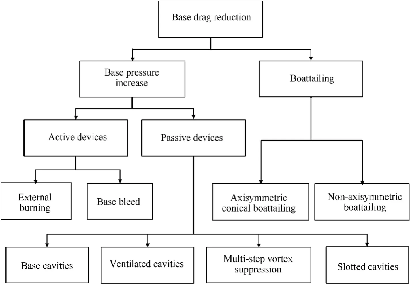
Fig.1. Methods of base drag reduction.
The current study has been carried out using Reynolds Averaged Navier-Stokes (RANS) equations exploiting the computational facilities of Ansys Fluent.The determined drag coefficients have been compared to the results of the experimental work performed by Platou [18]. The shock wave formation, base flow, drag reduction and overturning moment are of main concern in the present study.
2. Computational work
The current study has been applied to a projectile of 57 mm caliber. The relative dimensions of the used projectile models in terms of the caliber are shown in Fig. 2. The triangular boattail is formed by cutting three planes with an angle of 7°in the cylindrical part as shown in Fig. 2(b).
In order to compare the results of computational work with those of experimental work,the current CFD simulations have been performed on TBP model which had been experimentally tested by Platou [18]. This projectile model has no twist and the spinning is imparted to it through its cupper driving band which is engraved into the grooves (rifling) of the weapon barrel.
2.1. Governing equations

Fig. 2. Relative dimensions of the projectile models.
The governing equations are applied to each control volume in the computational domain for fixed cell volume V and incremental surface area dA=of its faces. These equations in the threedimensional Cartesian coordinate system can be written on the following conservation form [22]:

where

is the matrix of conservative properties. The components of the inviscid flux vector F are:

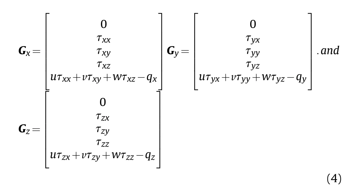
and the components of G are:
The air is considered as an ideal gas. The dynamic viscosity of the air is modeled using Sutherland's viscosity law with three coefficients.The momentum equation can be written as the following[22]:

The implicit density base scheme has been used to solve the system of differential equations.A slight modification to the system of Eq. (1) is made by transforming the dependent variable from conserved quantities W to primitive variables Q using the chainrule [22]. Then the system of equations is preconditioned by replacing the Jacobian matrix ∂W/∂Q with the preconditioning matrix Γ [25,26].
The second-order upwind scheme has been applied in discretizing the spatial dependent properties in RANS equations.Higher-order accuracy is achieved at the cell faces through a Taylor series expansion of the cell-centered solution about the cell centroid. Thus the face value φfis computed using the following expression [22]:

2.2. Grid generation
The grid sensitivity study has been carried out using 2-D structured quadrilateral grid (see Fig. 3) of five sizes. Fig. 4 shows the total drag coefficient,at upstream Mach number equal to 0.96,versus the grid size (N) normalized by the size of the used grid(NG=26000 cells) since the increase of number of cells makes insignificant change of the total drag coefficient.
For CBP,the 3-D full domain structured grid has been generated by rotating the chosen 2-D grid around the projectile axis to get a grid size of 1828800 cells as shown in Fig. 5. The pressure far field boundary is approximately located at a distance equal to five times the projectile length. This distance has been firstly taken from the literature[16].Then an investigation has been carried out to check if it is sufficient distance to set up the far field boundaries.Then,it has been found that the pressure values are of insignificant changes near the far field boundary.
For TBP,the 3-D full domain structured grid has been generated with grid size of 1867200 cells as shown in Fig.6.The boattail part consists of three flat and three round surfaces which have been divided into sub-surfaces to improve the grid quality as shown in Fig. 7. Thus, the computational domain is comprised of forty six sub-volumes. The value of the wall function y+ < 1 has been checked satisfying the used turbulence model.
2.3. Boundary conditions
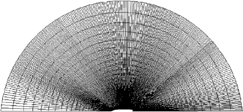
Fig. 3. Structured 2-D grid around CBP model.
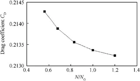
Fig. 4. Drag coefficient versus normalized number of cells at M=0.96 for CBP model.
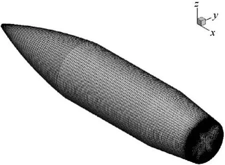
Fig. 5. Three-dimensional grid for CBP.
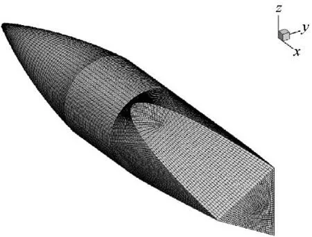
Fig. 6. Three-dimensional grid for TBP.
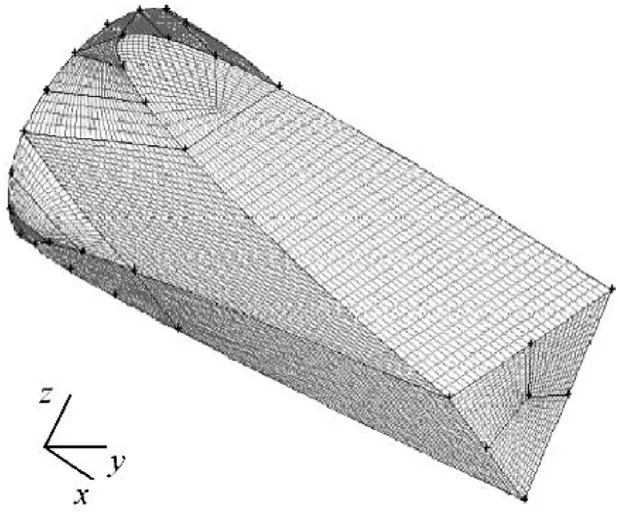
Fig. 7. Grid generation over the boattail of TBP.
The adiabatic no-slip condition is considered on the walls of the used models. The pressure far-field is applied to the outer boundaries of the computational domain. The static pressure and temperature for the pressure-far-field boundary are based on the total pressure p0=101325 Pa and temperature T0=330 K used in wind tunnel testing performed by Platou [18]. The static pressure and temperature are calculated from the isentropic flow relations of a perfect gas [27] as follows:

3. Results and discussions
3.1. Validation of the computational work
The wind tunnel measurements of total drag coefficient versus Mach number performed by Platou [18] have been chosen to validate the computational work. Fig. 8 depicts the experimental and computational results of the total drag coefficient versus Mach number for CBP and TBP, respectively. Good agreement is noticed between the computational and the experimental results. Table 1 lists the measured and calculated drag coefficients. It can be noted that the absolute values of the difference between computed and measured values is almost less than 5%. However, at Mach number ranges from 0.94 to 0.98 the difference is relatively large due to the drag divergence which normally occurs when the flying speed approaches the sonic value. The Mach number of drag divergence depends mainly on the geometry of the body.Physically,a formation of supersonic pocket occurs during increasing the flow speed toward sonic speed. The supersonic pocket is enlarged with the speed increase and terminated by a shock wave resulting in flow separation. This separation is the main reason of the drag increase with a high rate.
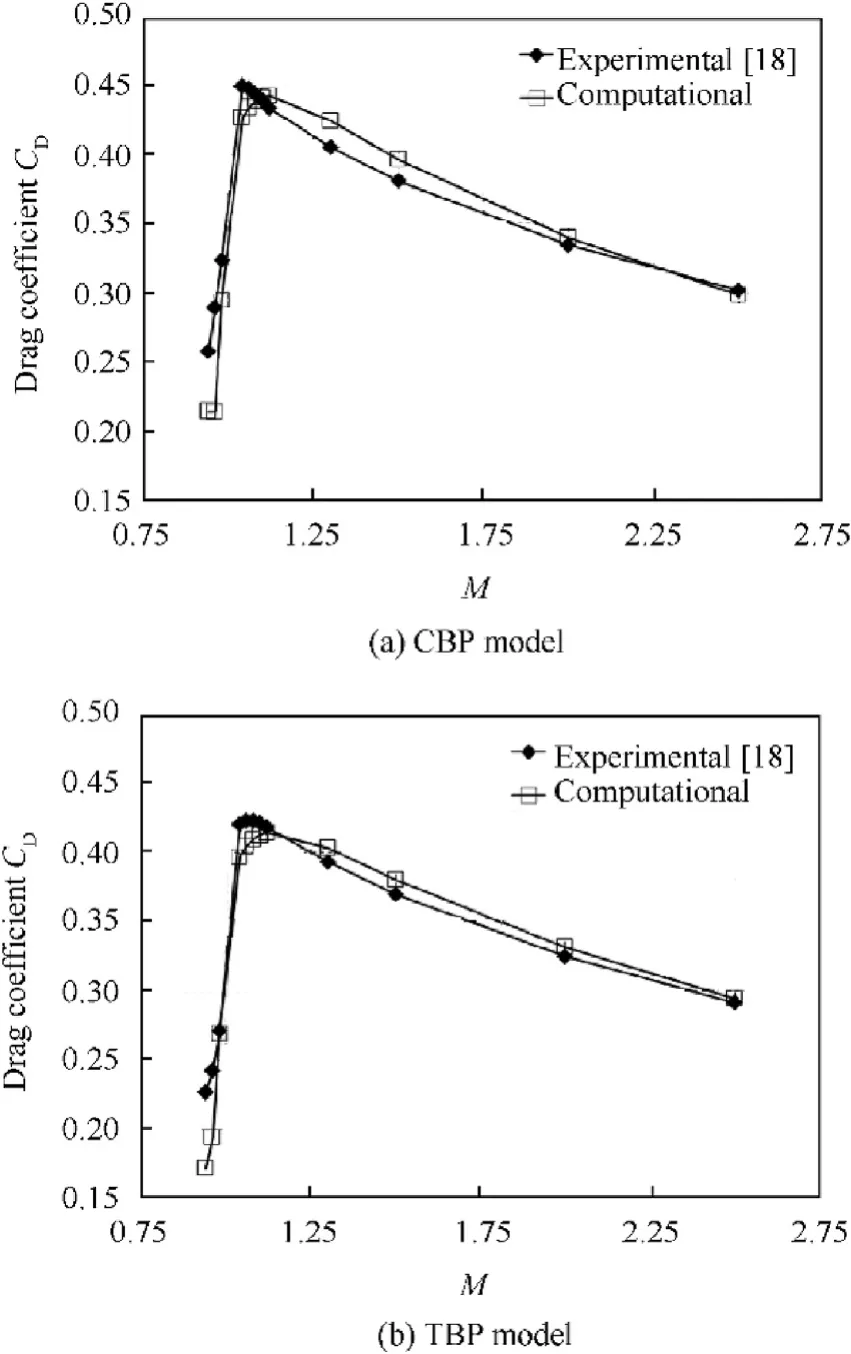
Fig. 8. Experimental and computational drag coefficients versus Mach number.

Table 1 Data of experimental and computational drag coefficients.
3.2. Shock wave formation
The shock wave formation is discussed at Mach number M=2.0 as an example of the flow at supersonic speeds, whereas M=0.96 has been chosen as an example of the flow at transonic speeds.For the remaining Mach numbers at both flow regimes (transonic or supersonic), the results of the shock wave formation are of the same qualitative main characteristics.
Fig.9 displays the Mach contours around CBP model at a plane passing through the projectile axis at M=0.96.It can be noted that two normal shock waves are almost impinging the middle of both the cylindrical and boattail parts. Fig. 10 displays three planes passing through TBP.Plane 1 divides the TBP into two symmetrical parts and perpendicular to one of the flat surfaces. Planes 2 and 3 are inclined by angles of 30°and 60°measured from Plane 1 in clockwise direction, respectively.
Fig. 11 displays the Mach contours over the aforementioned three planes. Unlike the case of CBP model, a single normal shock wave impinges the boattail part of TBP model at a distance less than four times the projectile caliber measured from its nose.This single normal shock wave is relatively smeared, especially at the round surfaces, i.e. Plane 3.
Figs.12 and 13 display the Mach contours around CBP and TBP models at upstream Mach number M=2.0, respectively. The figures show compression waves behind the base of both projectiles generated on the free shearing layers.These compression waves are collected together to form an oblique shock wave. It can be noted that the shock wave is smearing in case of TBP especially at plane 3 compared with the shock wave formed in case of CBP.
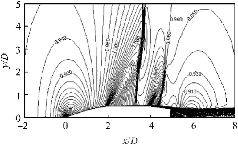
Fig. 9. Mach contours around CBP at M=0.96.
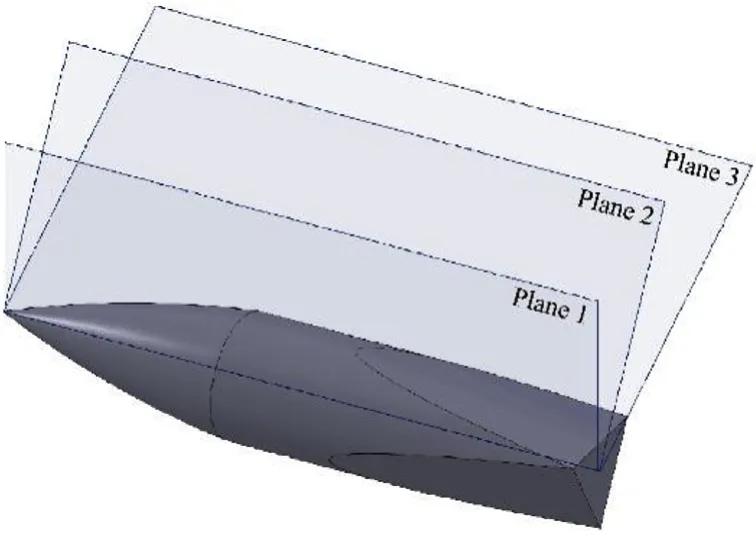
Fig.10. Demonstrative planes along TBP.
It is thought that the three round surfaces make flow relaxation resulting in: i) prevention of the normal shock wave formation on the cylindrical part at transonic speeds, and ii) smearing of the shock waves at supersonic speeds.
3.3. Base drag
Fig.14 shows base drag coefficient versus Mach number.Lower base drag coefficient is incurred in case of TBP compared to CBP.The base drag reduction may be reasoned by the base area reduction of TBP which is approximately three quarters its CBP counterpart.
Fig.15 displays the streamlines past the base of both CBP and TBP at upstream Mach number ranging from 0.94 to 2.5. It is clear that, the wake zone past TBP is always smaller than its CBP counterpart and the streamlines are not symmetric. Diminishing of the wake zone results in a reduction in the vortices behind the base.Therefore base drag reduction and lower level of turbulence are obtained.
Fig. 16 illustrates the position of the rear stagnation point measured from the projectile base (Xs) normalized by the caliber(D) against the upstream Mach number. In general, the rear stagnation point moves downstream by increasing the free stream subsonic speed.However,it moves nearer to the base by increasing the free stream supersonic speeds,which is in agreement with the results of Ref. [28]. Also, it can be noticed that the rear stagnation point is always closer to the base in case of TBP.
3.4. Overturning moment
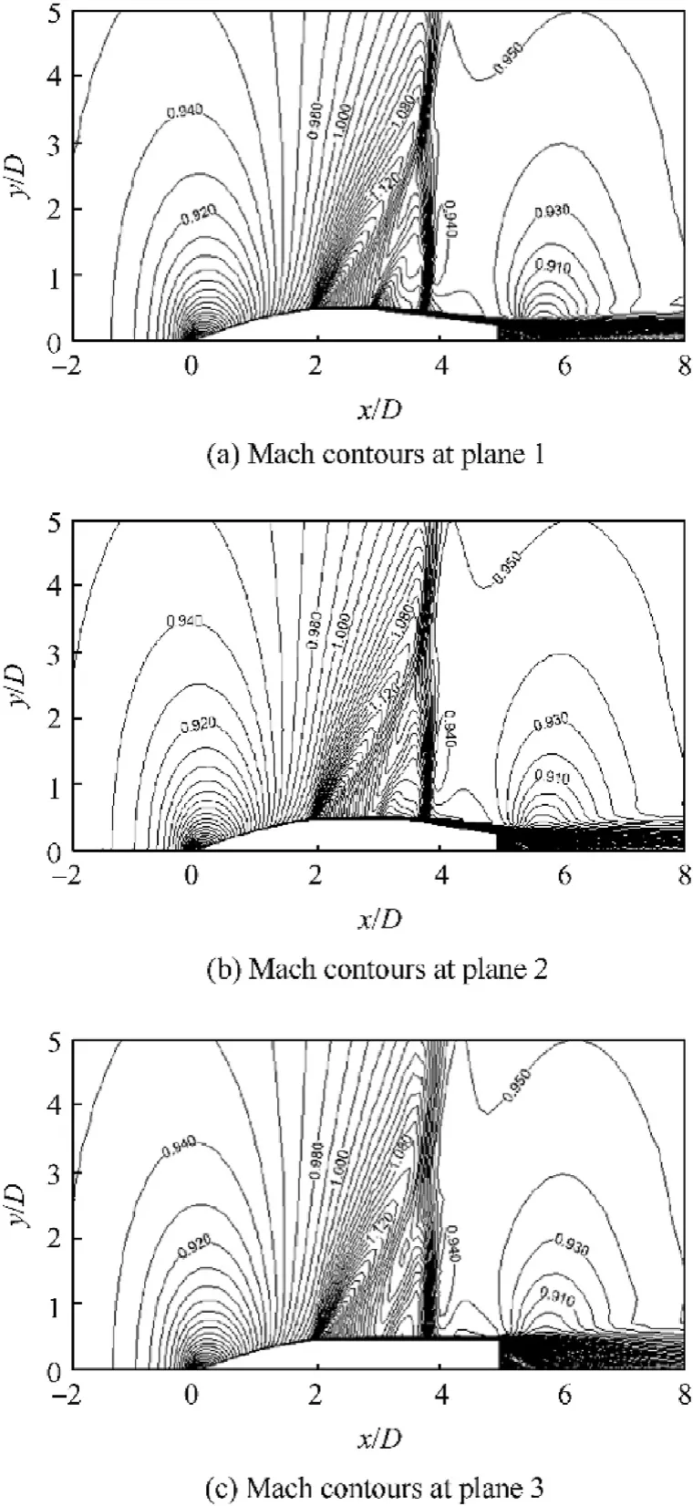
Fig.11. Mach contours around TBP model at M=0.96.
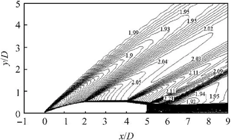
Fig.12. Mach contours around CBP at M=2.0.
The conventional artillery projectiles of ogival boatatiled shapes are usually aerodynamically unstable since the center of pressure of the aerodynamic forces is located in front of the center of gravity.Therefore, the normal force generates an overturning moment about the center of gravity. This moment acts on the projectile causing the angle of attack (AOA) to increase. In this case, the moment is positive;consequently its coefficient CMα is also positive.To resist this overturning moment, a gyroscopic effect acts on the projectile by imparting it a very high spin rate through the rifling of the weapon barrel.
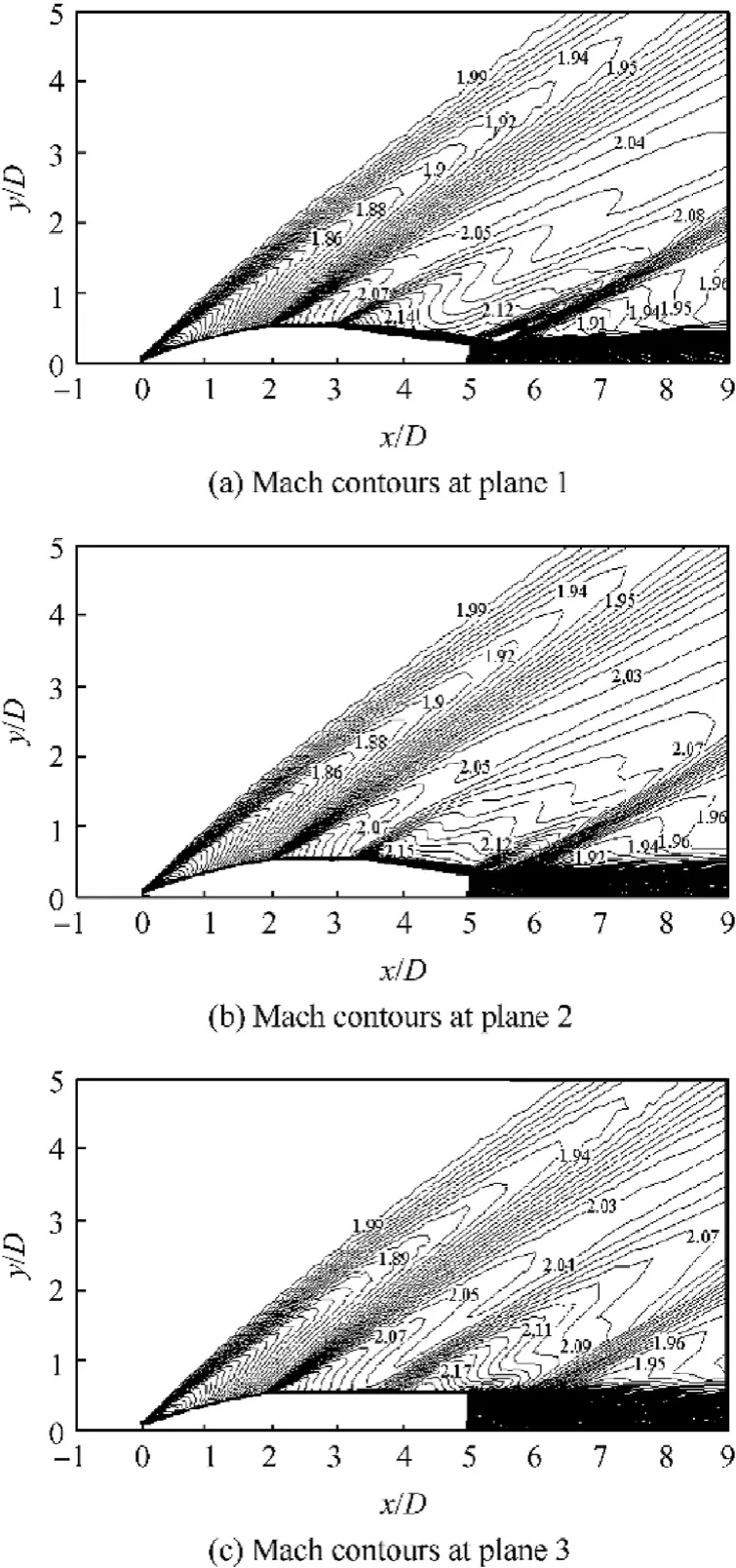
Fig.13. Mach contours around TBP at M=2.0.
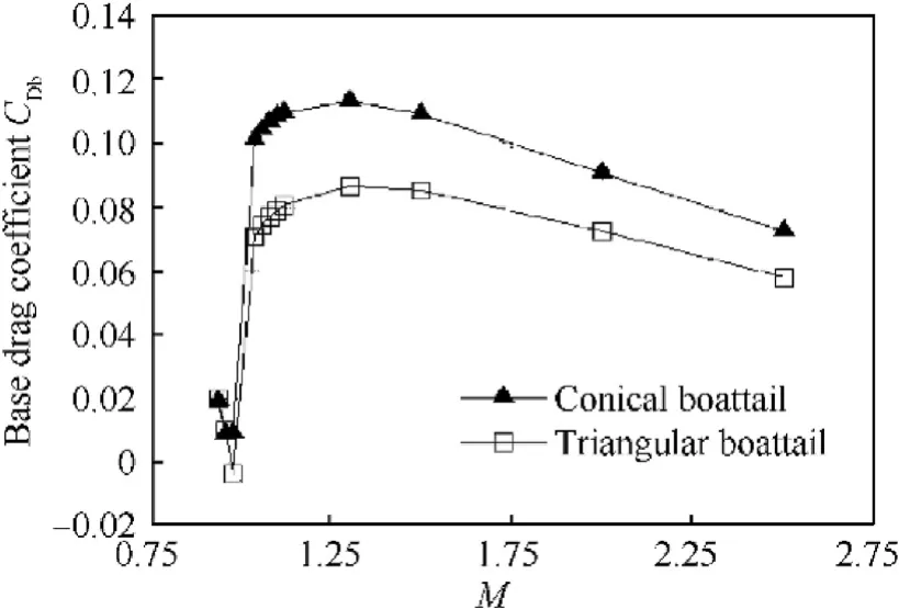
Fig.14. Base drag coefficient CDb versus Mach number.
The overturning moment coefficient at AOA of ±3°has been calculated to evaluate the aerodynamic stability of TBP with respect to CBP. The positions of the center of gravity of the projectile models have been obtained through CAD drawings using Solid-Works. Utilizing the results of CFD simulations, the overturning moment coefficients have been calculated about the determined centers of gravity.
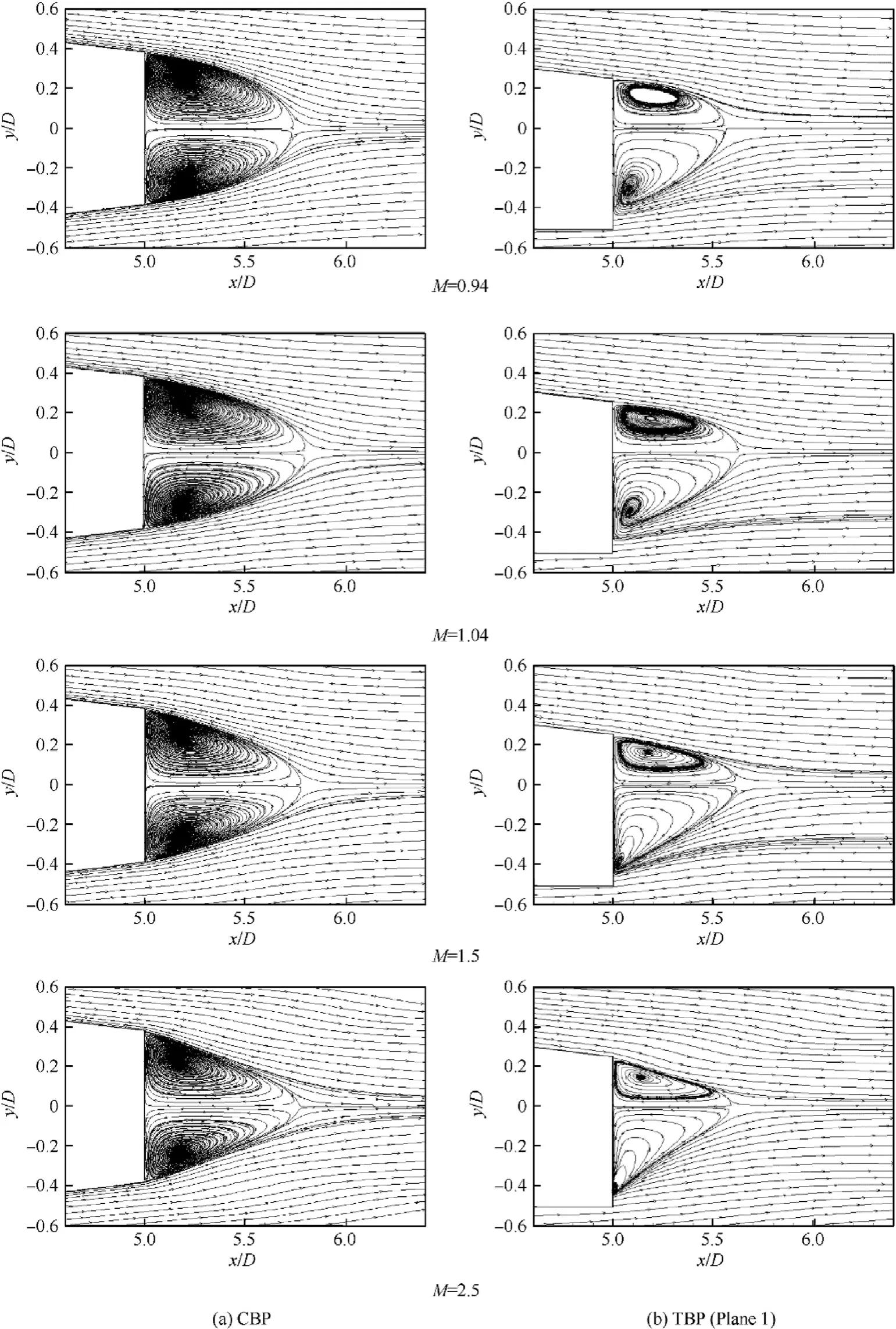
Fig.15. Streamlines past the base of CBP and TBP at plane 1.
Fig.17 illustrates the overturning moment coefficient CMα versus Mach number.This coefficient has been calculated at AOA equal to 3°in case of CBP.Whereas,in case of TBP,it has been calculated at AOA=±3°.At AOA=-3°,the flow faces the flat surface.However,at AOA=+3°,the flow faces the round surface.Whatever the value of the AOA,CMαis of smaller values in case of TBP compared to the values in case of CBP.Also,CMα is favorable when the flow faces the flat surface of TBP since the distance between the center of pressure and the center of gravity decreases.The decreasing of this distance results from the higher pressure distribution on the flat surface.
4. Conclusions and recommendations
The study concludes that the flow over TBP is characterized by smearing of the formed shock waves and decreasing of the wake region behind the base resulting in nearer rear stagnation point.Therefore,a base drag reduction of approximately 5%is obtained at M>1.0 when comparing to CBP.
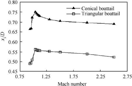
Fig.16. Normalized position of rear stagnation point versus Mach number.
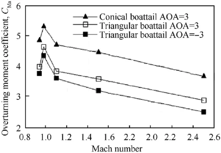
Fig.17. Overturning moment coefficient versus Mach number.
Also,the study concludes that TBP has better performance from stability point of view. This is reasoned by moving the center of pressure toward the center of gravity resulting in decreasing of the overturning moment.
All the results of the current study have been determined when the value of TBP flat surfaces inclination angle is of 7°.Therefore,it is recommended to carry out a parametric study investigating the ballistic performance of TBP when changing this inclination angle.
杂志排行
Defence Technology的其它文章
- Statistical variability and fragility assessment of ballistic perforation of steel plates for 7.62 mm AP ammunition
- Texture evaluation in AZ31/AZ31 multilayer and AZ31/AA5068 laminar composite during accumulative roll bonding
- Local blast wave interaction with tire structure
- Research and development of training pistols for laser shooting simulation system
- Summed volume region selection based three-dimensional automatic target recognition for airborne LIDAR
- A novel noise reduction technique for underwater acoustic signals based on complete ensemble empirical mode decomposition with adaptive noise, minimum mean square variance criterion and least mean square adaptive filter
