Optimization of reluctance accelerator efficiency by an improved discharging circuit
2020-06-28HuiminDengYuWangFalongLuZhongmingYan
Hui-min Deng, Yu Wang, Fa-long Lu, Zhong-ming Yan
School of Electrical Engineering, Southwest Jiaotong University, Chengdu, 610031, China
Keywords:Reluctance accelerator Suck-back effect Discharging circuit Current decay Efficiency optimization
ABSTRACT In this paper, an improved discharging circuit was proposed to quicken the decay of the current in the drive coil in a reluctance accelerator when the armature reaches the center of the coil. The aim of this is to prevent the suck-back effect caused by the residual current in drive coil. The method is adding a reverse charging branch with a small capacitor in the traditional pulsed discharging circuit. The results under the traditional circuit and the improved circuit were compared in a simulation. The experiment then verified the simulations and they had good agreement. Simulation and experiment both demonstrated the improved circuit can effectively prevent the suck-back effect and increase the efficiency. At the voltage of 800 V, an efficiency increase of 36.34% was obtained.
1. Introduction
Electromagnetic launch technology provides a competitive alternative to traditional chemically-driven propulsion by virtue of its distinct advantages [1-4]. Electromagnetic launchers have the potential uses in transportation, military and space applications[5-8]. They are generally categorized into two types: railgun and coilgun[2].Compared with railgun,coilgun has no physical contact with armature, which has low wear of the system and long operational lifetime [8-10]. Two mechanisms of coilgun to accelerate the armature are induction and reluctance. The armature in induction-type is conductive and non-magnetic, and the force is developed by the interaction between the magnetic field generated by the current in drive coil and the induced eddy current in armature.The armature of reluctance-type coilgun is ferromagnetic material.The force is developed by the change of reluctance in the magnetic circuit when the armature moves [5]. Reluctance-type coilgun is also called reluctance accelerator that requires lower current than induction-type to generate appreciable acceleration for the armature, which simplifies the switching circuit, but still exhibits relatively good efficiency than induction-type [5,7,9]. A simpler and even smaller armature can be used in this accelerator[10]. In hostile environment, the reluctance accelerator can maintain structural reliability and robust performance,which is another advantage [5,9]. Furthermore, reluctance accelerators have been used as a variety of actuators and electromagnetic tools in practical applications[7,12].
Reluctance accelerators have attracted much attention in recent years, and many studies have been done to increase its efficiency[8-24]. Due to the principle of force, reluctance accelerators are only able to pull but not to push the armature.When the armature enters the drive coil, the electromagnetic attraction exerts a force on the armature and pulls it to the middle point of the coil.Once the armature begins to leave the center of the coil with a residual current, the force will be reversed and retard the armature. This phenomenon is considered as suck-back effect, which will reduce the efficiency [5,7,9,19-21,24]. Designing an appropriate discharging circuit to quicken the decay of the current is beneficial in reducing the influence of suck-back, and the efficiency will be improved accordingly. Currently, most of the circuits are designed to add an external quenching resistor or heat dissipators in the branch of freewheel diode to damp the current [7,9,18-20]. But some of electric energy will be consumed as the heat in the resistor,and the switches and the resistor are risk of burn-out under high voltage.Bresie et al.proposed to apply a negative voltage across the coil when the armature approaches to the center of it [5]. But this method is only theoretically feasible, and will make the drive system complex and lower the efficiency [19]. Cooper et al. [21]adopted a MOSFET driver to truncate the current pulse to increase the relative efficiency compared to the unaltered current pulse.However, this circuit design will also cause some energy consumption and reduce the efficiency of the system.
To solve this problem mentioned above,we design an improved discharging circuit. A reversed charging branch is added in the traditional discharging circuit and Insulated Gate Bipolar Translator(IGBT) is applied between the freewheel diode and drive coil. The branch consists of a capacitor with small value and a thyristor.This circuit not only makes the current drop to zero quickly but also stores the residual electric energy in the capacitor to be recycled and reused for other purposes.This circuit has good controllability and reduces the energy consumption. We simulated the finite element model and conducted experiments under traditional and this improved discharging circuit,respectively.The results verified that this improved circuit can effectively prevent the suck-back effect and increase the efficiency significantly.
2. Reluctance accelerator design
2.1. Design principle
The structure of the reluctance accelerator is shown in Fig.1.The accelerator consists of a drive coil, an armature made of ferromagnetic material and a tube.When the drive coil is energized by a power,the magnetic force will pull the projectile into the coil until it passes the middle point of the drive coil.If the drive coil still has current flowing through it at this time, a retarding force will be generated and decelerate the projectile.So the current must be cut off as quickly as possible when the centerlines of the projectile and the drive coils are about to coincide (shown in Fig. 2).
2.2. Circuit description
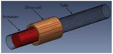
Fig.1. The structure of the reluctance accelerator.
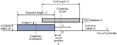
Fig. 2. The cross-section view of the reluctance accelerator.

Fig. 3. Drive circuit schematic diagram.
The drive circuit of the reluctance accelerator is shown in Fig.3.The left part is a traditional pulsed discharging circuit,the right one is an improved discharging circuit with a reverse charging branch including a capacitor C2 with a small value and thyristor THY1.VDC1 is the DC voltage source, which is charging for the capacitor bank C1. Freewheeling diode D1 is used to prevent the reverse current and constitute a loop with the drive coils to allow the current to decay.L1 and R1 stand for the inductance of the drive coil and the sum resistor value of the drive coil and the branch circuit.Compared with the traditional circuit,IGBT replaces the thyristor in the improved circuit,because the branch containing D1 needs to be disconnected. Only then can the current flow to the branch of the reverse charging branch.
There are three parts in the whole discharging process. Firstly,when the thyristor is off and IGBT1 is on,the drive coil is energized by the capacitor bank. The current flows through the RLC circuit composed of R1,L1,and C1.Secondly,when the voltage of capacitor reduces to zero,the current will flow through D1,and the current in the coil decays according to the exponential law expected of RL circuit. This is the second part of the discharging process. Finally,once armature is getting to the center of the coil,IGBT is turned off and thyristor is switched on. The current flows through C2 and drops to zero quickly. The residual voltage direction of C2 is opposite to the initial charging voltage direction.
2.3. Circuit analysis
At the first part of the discharging process,the circuit is modeled as an RLC circuit,Kirchhof's voltage law is written as
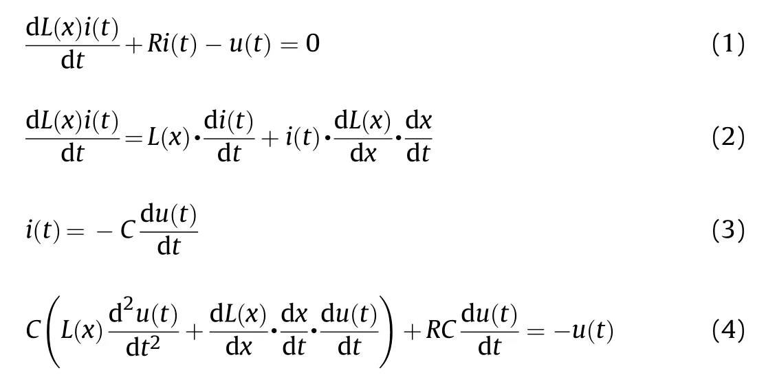
where L(x) is the inductance of drive coil, which depends on the position of armature.C is the capacitance of the capacitor bank for discharging.R is the resistor of the circuit,u(t)is the voltage of the capacitor bank,and i(t)is the current in coil.When the discharging process comes to the second part, the electric equation in this RL circuit can be expressed as

The circuit in the third part of the discharging process can also be solved by Eq. (4). But the C and u(t) are referred to the capacitance and the voltage of C2, respectively.
To choose an appropriate value for the reverse charging capacitor, we must study the relationship between the drop time of the current and the value of the reverse charging capacitor.Because the displacement variation of armature during the current quick decay is tiny, we suppose that inductance of drive coil is constant to simplify the calculation.By solving the equations of RLC circuit,the expression of decay time is written as

By calculating Eqs. (6) and (7), the curve of decay time vs.reverse charging capacitance is shown in Fig.4.It can be concluded from the figure that the smaller the capacitor value of C2 is, the time of the current drops to zero is shorter.
3. Simulation analysis
The numerical calculation of the circuit and the force acted on the armature is complicated, therefore the finite element method(FEM)simulation software ANSYS Maxwell is utilized to analyze the motion of the launcher. Maxwell 2-D magnetic transient solution type was used in this simulation. In this section, the simulation model is described; the different currents and forces between traditional circuit and the improved discharge circuit are analyzed;the performance differences between the two circuits are compared.
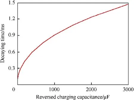
Fig. 4. Current decay time vs. the reversed capacitance (L=400 μF, R=200 mΩ.).
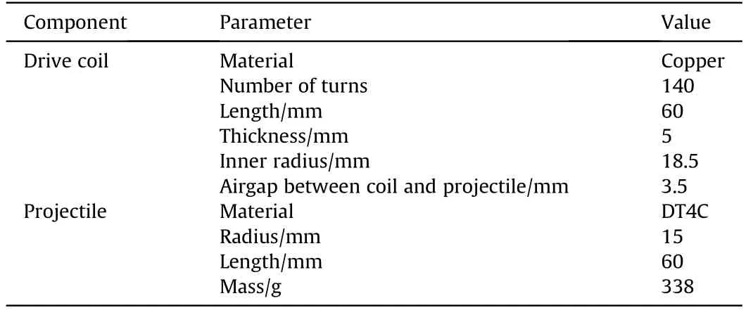
Table 1 Transient simulation model dimensions.
3.1. Simulation model
The cross-section view of the 2-D simulation model is shown in Fig.2,which is on z-axis symmetry.Table 1 exhibits the dimension of the simulation model. P (shown in Fig. 2) represents the initial position, which is the distance from the centerline of drive coil to the front-end of the armature. Initial position can affect the performance of the launcher, and an optimal position makes the armature gain the maximum kinetic energy[23,24].Comparing the results by several simulations, the value of the optimal initial position in this model is set to -15 mm. The external circuit used in this simulation was shown in Fig.3.The capacitances of C1 and C2 are 1600 μF and 25 μF, respectively. The initial voltage of the capacitor bank is set to four different values: 500 V, 600 V, 700 V,and 800 V.
It is can be seen from Table 1 that the length of the coil is as long as that of armature.When the lengths of the coil and armature are the same,the efficiency reached the maximum[15].The material of armature is the iron DT4C, which has a high saturated magnetic flux density (Bsat ≈2.2 T). This is a comparative study with the same armature.
3.2. Simulation results analysis
Take the 800 V for example,the curves of the current,speed,and force under traditional circuit are shown in Fig. 5. When the armature enters the coil, an attraction force is acted on the armature and pulls it to the center of the drive coil. The current in traditional circuit decays according to the exponential law expected of a RL circuit(as a consequence of the drive circuit resistance and the coil inductance). When the armature passes the center of the coil, the current has not yet fully attenuated. Therefore, a reverse force is generated and acted on the armature, and the speed is decreased by this suck-back effect. The efficiency will also be reduced correspondly.
To decrease the current in coil to zero as soon as possible when the armature reaches the center of the coil, the quick discharging circuit is designed and simulated. The simulation curves of the current, speed, and force under the improved circuit are shown in Fig.6.At 5.45 ms,the small capacitor begins to be reversely charged by the current in coil, and the current is reduced to zero in about 0.2 ms. Compared with the simulation curves of the traditional circuit, the force is always positive, and there is no retarding force after the speed reaches the maximum. Therefore, the suck-back effect is effectively restrained.
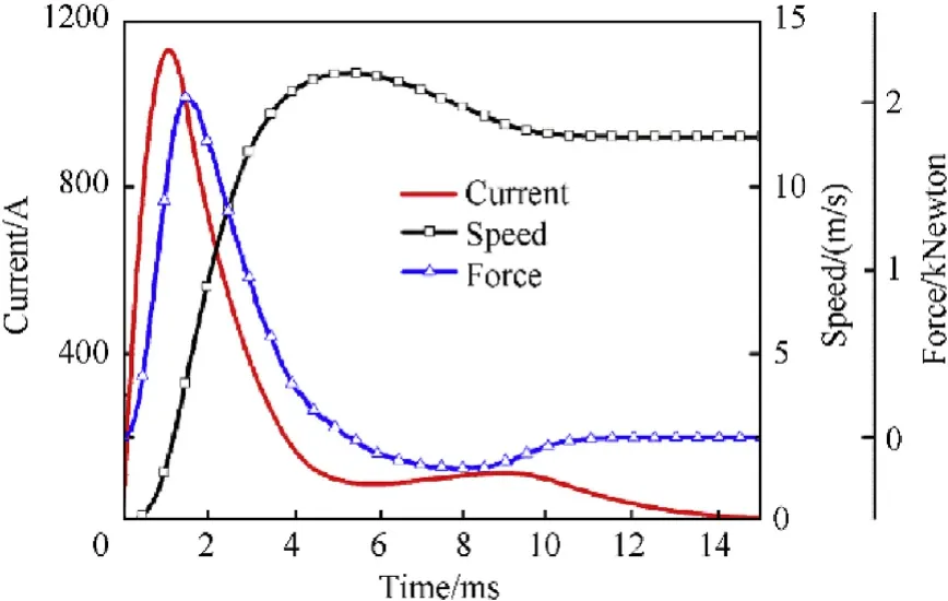
Fig.5. The simulation curves of current,speed, and force under the traditional circuit at the voltage of 800 V.
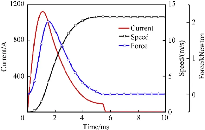
Fig.6. The simulation curves of current,speed,and force under the improved circuit at the voltage of 800 V.
The simulation results of different voltages are listed in Table 2.Under the traditional circuit,it has the highest efficiency of 5.25%at the voltage of 500 V. The efficiency decreases as the increase of voltage, and there is a certain gap between the highest efficiency and the lowest one.The muzzle speed and efficiency are improved relatively in comparison with the traditional circuit. Especially at the voltage of 800 V, the speed achieved was to 13.34 m/s and the increment of efficiency is up to 34.78%. Meanwhile, the potential difference (p.d) developed across the capacitor C2 is 358 V. In the traditional circuit, the current increases with the increase of voltages,which causes that the suck-back effect is more distinct and the efficiency is lower. Simulation results demonstrated that the improved circuit can eliminate the suck-back effect and effectively increase the efficiency.
4. Experimental research
4.1. Experimental platform construction
The experimental equipment in this paper is composed of a launcher, pulsed power supply, switches, control system, sensor,velocity-measuring system, data acquisition and processing system. The layout of the experimental equipment is shown in Fig. 7.Eupec's IGBT FZ1200R33KL2C was selected in this experiment. Its rated voltage,rated current,turn-on delay time,and turn-off delay time are 3.3 kV,1.2 kA,1.05 μs, and 3.70 μs, respectively. Fig. 8 displays the structure of the launcher,which consists of an armature,a former,a drive coil.The cylindrical armature is made of iron DT4C.1.5 mm enamelled wires are wound around the skeleton made of nylon to be assembled as the drive coils. A cylindrical hollow was dug in the nylon skeleton,which provides the motion track for the armature.
The dimensions of the drive coil and the armature are shown in Table 1. The inductance and resistance value of the drive coil are measured by LCR meter. The inductance and resistance value are 403.58 μH and 228.94 mΩ. In this experiment, the charging voltages for the capacitor bank are set as 500 V,600 V,700 V,and 800 V,respectively. The discharging capacitance and reversed charging capacitor are 1600 μF and 25 μF.The selected capacitor and voltage are all based on our existing experimental condition.
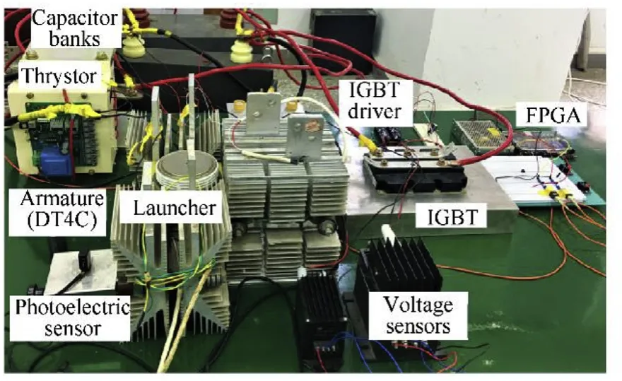
Fig. 7. Experiment layout of the reluctance accelerator equipment.
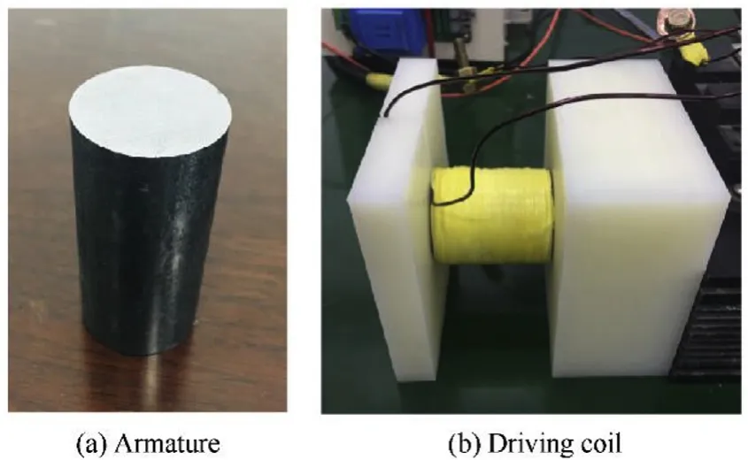
Fig. 8. (a) Armature (iron DT4C). (b) Drive coil.
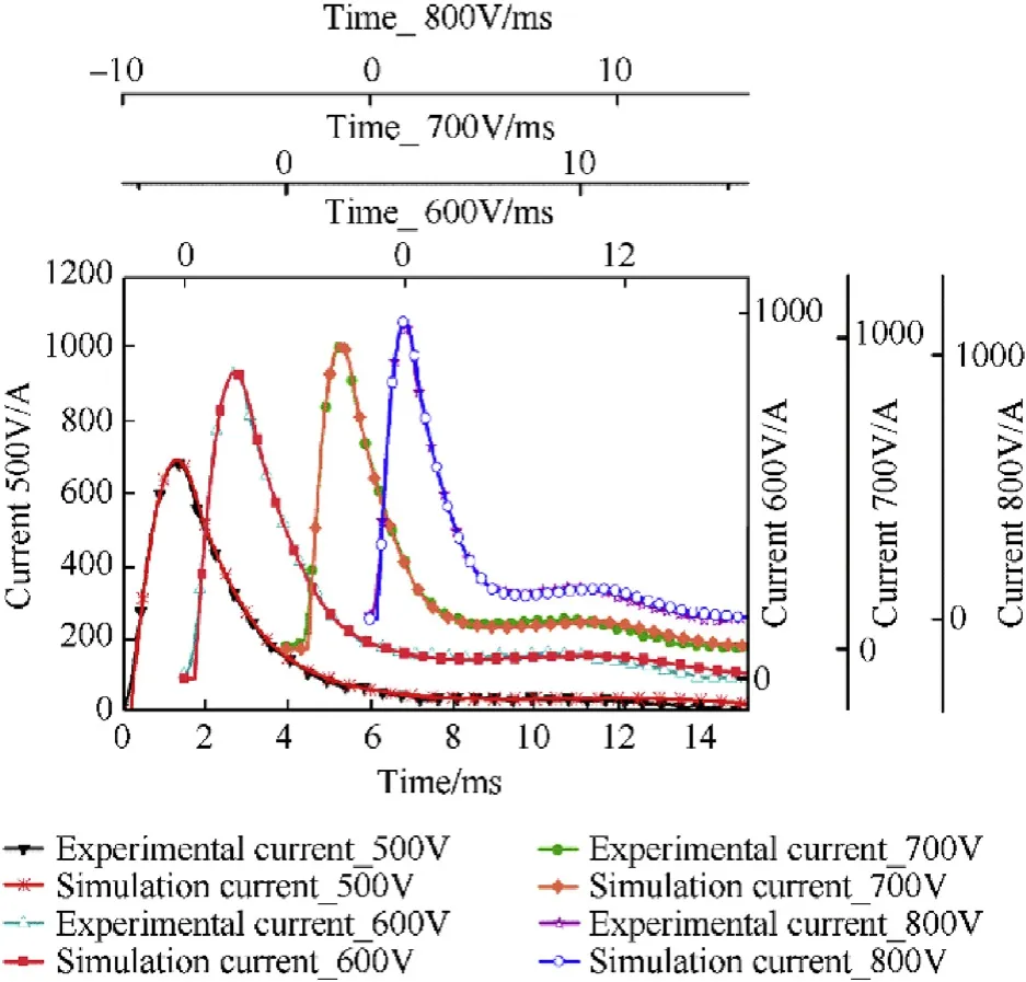
Fig. 9. Simulation and experimental currents in drive coil of different voltages under the traditional circuit.

Table 2 Simulated results of different voltages with traditional circuit and improved circuit.
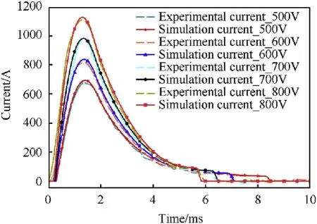
Fig.10. Simulation and experimental currents in drive coil of different voltages under the improved discharging circuit.
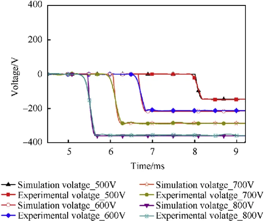
Fig. 11. Simulation and experimental residual voltages in reverse charging capacitor under the improved circuit.
4.2. Experimental results analysis
The experiments were both conducted under traditional circuit and the improved circuit.The simulation and experimental curves of currents with different voltages under traditional circuit are shown in Fig.9.It appears that the curves of the experimental and simulation current nearly coincide.It can be seen that the currents all have a slight rise before the end of the attenuation. These are caused by the returning energy to the magnetic field from the armature kinetic energy when the armature experiences a retarding force by the residual currents in the coil[6].This phenomenon was appeared both in the simulation and experiment results,which demonstrated that the experiment is consistence with the simulation model.
At different voltages, the time to reach the middle of the coil is different. Therefore, in the simulation of the improved circuit, the pulse duration was adjusted for maximum muzzle speed for each voltage. The simulation indicate that when the IGBT turns off at 8 ms,6.65 ms,6.05 ms,and 5.45 ms at the voltages of 500 V,600 V,700 V, and 800 V, respectively, the armature will gain the best performance. The higher the voltage, the shorter the time for armature to reach the middle point of drive coil.The simulation and experimental currents under the improved discharging circuit are shown in Fig.10.The bandwidth of the pulses at half-maximum of the output current is 2.1 ms. There are three orders of magnitude difference between the bandwidth of the pulses and the delay-time of the IGBT, so the effect of transient responses on the current is negligible.The retaining voltages of the reversed charging capacitor are shown in Fig.11.Good agreement between the experiment and the simulation was both observed in Figs.10 and 11.
Table 3 shows the experimental results under the two different circuits. Every velocity in this Table is the average value of 5-7 results under each experimental condition. The speed and efficiency are consistence with those in Table 2.An efficiency increase of 36.34% was obtained at the voltage of 800 V. Experiments also verified that this improved circuit can effectively eliminate the suck-back effect and increase the efficiency of reluctance accelerator.
5. Conclusion
This paper proposes an improved discharging circuit to eliminate the suck-back effect of the reluctance accelerator. The simulation was implemented to analyze how the residual current generates the retarding force exerted on the armature after it passes the center of coil. The performances under the two circuits are compared in the simulation. Experiments under different voltages are conducted and verified the simulations. The results between the simulation and experiment have good agreement.When the p.d applied across 1600 μF capacitor bank is 800 V, the armature was accelerated to the muzzle velocity of 13.33 m/s with the efficiency of 5.89%, which is 36.34% higher than that in the traditional circuit. Simulations and experiments both demonstrated that the improved circuit can effectively restrain the suckback effect and increase the efficiency. Because the discharging circuit in every stage of the multi-stage coil launching is the same,the improved circuit is applicable for multi-stage electromagnetic launching to prevent the suck-back effect. This approach also has application prospect in other designs which need fast power off and the reduction in wasted energy.

Table 3 Experimental results of different voltages with improved circuit and improved circuit.
Acknowledgment
This work was supported by the Fundamental Research Funds for the Central Universities [Grant number 2019XJ01].
杂志排行
Defence Technology的其它文章
- Statistical variability and fragility assessment of ballistic perforation of steel plates for 7.62 mm AP ammunition
- Texture evaluation in AZ31/AZ31 multilayer and AZ31/AA5068 laminar composite during accumulative roll bonding
- Local blast wave interaction with tire structure
- Research and development of training pistols for laser shooting simulation system
- Summed volume region selection based three-dimensional automatic target recognition for airborne LIDAR
- A novel noise reduction technique for underwater acoustic signals based on complete ensemble empirical mode decomposition with adaptive noise, minimum mean square variance criterion and least mean square adaptive filter
