Attitude deflection of oblique perforation of concrete targets by a rigid projectile
2020-06-28ZhuopingDunShuruiLiZhofngZhuochengOuFengleiHung
Zhuo-ping Dun , Shu-rui Li , Zho-fng M , Zhuo-cheng Ou , Feng-lei Hung
a State Key Laboratory of Explosion Science and Technology, Beijing Institute of Technology, Beijing 100081, PR China
b Beijing Institute of Technology, Zhuhai, Zhuhai 519088, PR China
Keywords:Oblique perforation Penetration Concrete target Attitude deflection Rigid projectile
ABSTRACT A perforation model is developed to predict the attitude deflection in the oblique perforation of concrete targets by a rigid projectile, in which the inertial moment of the projectile is introduced, together with taking the attitude deflection during the shear plugging sub-stage into account,and the shape of the plug formed on the rear surface of target is also re-investigated. Moreover, a new classification of concrete targets is proposed based on the target thickness,with which the attitude deflections in different kinds of concrete targets are analyzed.It is found that the numerical results by using the new perforation model are in good agreement with the previous experimental data and simulated results. Furthermore, the variations of the attitude deflection with the initial conditions (the initial attitude angle and the initial impact velocity) are investigated.
1. Introduction
Over the past decades, the penetration of concrete targets by a rigid projectile has been concerning continually in the field of impact and penetration, especially the attitude deflection during the oblique perforation process [1-11]. When a rigid projectile penetrates obliquely into a concrete target with finite thickness,the rigid projectile will perforate the target along a deflected path due to the asymmetric resistance, which is different from the normal perforation. Moreover, the well-known spalling phenomenon resulting from the reflected tensile waves will occur on the rear surface of target[12].
In order to describe such a complicated oblique perforation process, Chen et al. [3] have developed a three-stage model, in which the perforation process is divided into three sequent substages, namely, the initial cratering, the tunneling and the shear plugging sub-stages. The attitude deflection is characterized quantitatively by both the attitude angle (i.e. the acute angle between the axis of the projectile and the normal direction of the impacting surface of target) and the attitude deflection angle (i.e.the increment of the attitude angle). However, in their model, the attitude deflection was considered only in the initial cratering substage,and hence the attitude angle remains unchanged in both the tunneling and the shear plugging sub-stages, but which is not the case in experimental observations and numerical simulations[6,13-15].
In the oblique perforation experiments of the thick concrete targets, the residual attitude angles (i.e. the attitude angle at the last time of perforation)are generally larger than the initial attitude angles[16,17].While in the oblique perforation experiments of the thin concrete targets, the residual attitude angles are found to be less than the initial attitude angles [13,14]. Moreover, the same phenomenon has also been observed by the numerical simulations of oblique perforation of the thin concrete targets [6,15], which were investigated by incorporating a combined dynamic constitutive model into the LS-DYNA code, based on the Holmquist-Johnson-Cook (HJC) [18] and the Taylor-Chen-Kuszmaul (TCK)[19] models,with both the compressive and the tensile damage of concrete are described simultaneously. Consequently, it indicates that the directions of the attitude deflection in a thin target are obviously different from that in a thick target,which,however,was rarely mentioned before.
The oblique perforation process in a thin concrete target is only composed of two sub-stages, namely, the initial cratering and the shear plugging sub-stages [3]. After it deflects with an increasing attitude angle [4,20,21] during the initial cratering sub-stage, the projectile has to deflect oppositely during the subsequent shear plugging sub-stage to make the residual attitude angle less than the initial attitude angle. Therefore, the disregard of the attitude deflection in the shear plugging sub-stage makes the model developed by Chen et al.[3]fail to simulate the attitude deflection in oblique perforation of thin concrete targets.
In addition, there are two more issues need to be justified. On the one hand, Recht and Ipson [20,22] investigated quantitatively the attitude deflection angle during the initial cratering sub-stage with the initial momentum normal to the penetration path, but their results fail to evaluate quantitatively the effects of the initial impact velocity and the projectile geometry[3].Later,Chen et al.[3]obtained the attitude deflection angle during the initial cratering sub-stage by analyzing the kinetic energy consumption normal to the penetration path with two dimensionless numbers,namely,the impact function I and the geometry function N[1,23,24].However,although their results can describe quantitatively the effects of the initial impact velocity and the initial attitude angle, only the attitude deflection angle at the end time of the initial cratering substage can be estimated, rather than the time history of the attitude deflection angle during all sub-stages of perforation. On the other hand, while the projectile enters the shear plugging substage, a plug will be formed between the projectile nose and the rear surface of the target. Referring to the symmetric cone-shaped plug in normal perforation [25-27], Chen et al. [3] assumed an asymmetric oblique-crossed cone-shaped plug in oblique perforation, with both of their central axes being coincident with the direction of the projectile velocity. However, Jena et al. [28] have pointed out that the shock waves formed at the moment of impact will propagate spherically outward from the point of impact and finally reflect at the nearest surface, so that the damaged area on the rear surface caused by the reflected tensile waves is not in the direction of the projectile velocity in oblique perforation.Moreover,according to the experimental results of oblique perforation of thin concrete targets, the shapes of the damaged areas on the rear surface of targets were symmetric circles when the attack angles(i.e. the acute angle between the axis of the projectile and the direction of the projectile velocity)were negligible[7,13].It indicates that the asymmetric oblique-crossed cone-shaped plug assumed by Chen et al. [3] is questionable.
The purpose of this paper is therefore to develop a perforation model to describe the attitude deflection in oblique perforation of concrete targets, in which the inertia moment of the projectile is introduced, and the attitude deflection during the shear plugging sub-stage is taken into account together with introducing a corresponding deflection mechanism. Moreover, a new classification of the target thickness is presented, and the medium concrete target that has the medium thickness is first proposed. This paper is divided into four sections as follows.After this brief introduction,in Section 2,the perforation model is developed,which the three substages as well as the attitude deflections for different classes of target thickness are analyzed respectively and the determination method of the classes is presented. In Section 3, the numerical results by using the perforation model are presented and compared with a series of the previous experimental data and simulated results, moreover, the variations of the attitude deflection angle versus different initial conditions are investigated and the numerical results of the medium concrete targets are discussed. Finally,some conclusions are drawn out in Section 4.
2. Perforation model
In the analytical two-dimensional model, a rigid projectile moves in the ballistic plane(i.e.the plane determined by the axis of the projectile and the normal direction of the impacting surface of the target), which is subjected to the oblique target resistance.For the sake of simplicity, the concrete target is assumed to be homogeneous with the homogenized reinforcements and aggregates.As shown in Fig.1,there are usually three kinds of angles in describing such an attitude deflection process, namely, the attitude angle β,the attack angle δ and the oblique angle θ (i.e. the difference between the attitude angle and the attack angle). In this study, we focus mainly on the attitude angle β and define the attitude deflection angle Δβ=β-β0,in which β is the current attitude angle and β0is the initial attitude angle. In addition, the self-rotation of the projectile around its own axis is not taken into account and the attack angle δ is taken to be zero.
The other geometric parameters of the projectile and the target are shown in Fig.2,where H is the target thickness;d,h,L and lCare the diameter, the nose length, the body length and the distance between the nose tip and the mass centroid of the projectile,respectively; v0is the initial impact velocity.
As aforementioned, the total oblique perforation process of the concrete target is divided into three sub-stages,namely,the initial cratering, the tunneling and the shear plugging sub-stages. The projectile does not deflect during the tunneling sub-stage because of the symmetric lateral resistance, but it will deflect in both the initial cratering and the shear plugging sub-stages with opposite directions. Therefore, as depicted in Fig. 3, the attitude deflection angle is positive during the initial cratering sub-stage but negative during the shear plugging sub-stage.
To describe the motion of the projectile during the oblique perforation, in the ballistic plane, three Euler rectangular coordinate systems (x1, y1), (x2, y2) and (x3, y3) are established for the initial cratering, the tunneling and the shear plugging sub-stages,respectively. Each of the three Euler rectangular coordinate systems is determined at the initial time of the corresponding substage, with the origin located at the projectile nose and the xiaxis(i=1,2,3)is along the positive axis of the projectile and(xi,yi)forms a right hand system. Moreover, the motion and the stress analysis of the projectile at the initial time of each perforation substage is shown in Fig. 4, where Fniand Fti(i=1, 2, 3) are the axial resistance and the lateral resistance, respectively, and V0iand B0i(i=1,2,3)are the initial projectile velocity and the initial attitude angle of each sub-stage, respectively.
The differential equations of motion of the projectile in each sub-stage are
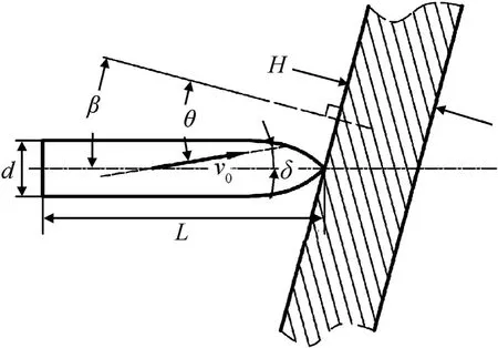
Fig.1. The attitude angle β, the attack angle δ and the oblique angle θ.

Fig. 2. Geometric parameters of the rigid projectile and the concrete target.
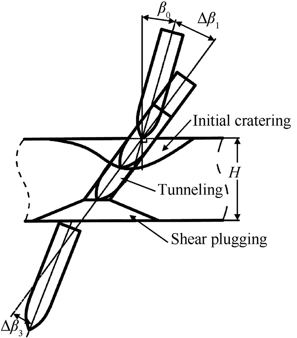
Fig. 3. Attitude deflection during three perforation sub-stages.
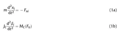
where i=1, 2, 3 represent the initial cratering, the tunneling and the shear plugging sub-stages, respectively, m is the mass of the projectile, xirepresents the trajectory distance during each substage, MC(Fti) is the torque of Ftito the projectile centroid, and JCis the inertia moment passing through the projectile centroid and normal to the ballistic plane.
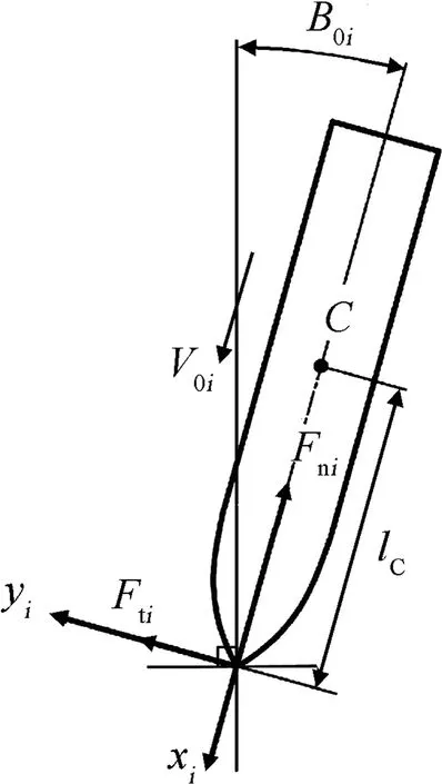
Fig. 4. Motion and stress analysis of the projectile at the initial time of each perforation sub-stage.
2.1. Analyses of three sub-stages in oblique perforation
2.1.1. Initial cratering sub-stage
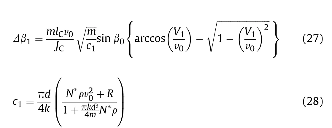
In the initial cratering sub-stage,the axial resistance Fn1is given by an empirical formula according to reference[29],and it satisfies the relationship of Eq. (2b) with the lateral resistance Ft1[3]. According to the stress analysis of the projectile shown in Fig. 4,MC(Ft1), the torque of Ft1to the projectile centroid, is obtained as
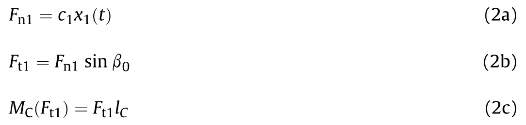
where c1is the resistance constant in the initial cratering sub-stage.
At the initial time of this sub-stage t=0, the initial trajectory distance X01=x1(0)=0, the initial projectile velocity V01=v1(0)=v0,the initial angular velocity Ω01=ω1(0)=0 and the initial attitude angle B01=β1(0)=β0. Substituting Eq. (2) into Eq.(1) leads to the initial-value problems for x1(t) and β1(t), which,under the aforementioned initial conditions,gives the solutions as
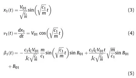
At the end time of this stage t=T1,we denote the end trajectory distance, the end projectile velocity and the end attitude angle of the first stage as X1=x1(T1), V1=v1(T1) and В1=β1(T1), respectively. Moreover, we define the first attitude deflection angle as Δβ1=В1-B01. From Eqs. (3)-(5), it reaches
In these equations, the end time of the first stage T1and the resistance constant c1are unknown yet and need to be determined in the following.
The initial cratering is also divided into the complete and the incomplete cases. For a target thick enough, the projectile will accomplish a complete initial cratering sub-stage, making the trajectory distance reach up to X1that can be determined by the following empirical formula [1,24].

where k = 0.707 + h/d is a dimensionless coefficient. However, in the case of incomplete initial cratering, more details of other substages are necessary to determine X1.
2.1.2. Tunneling sub-stage
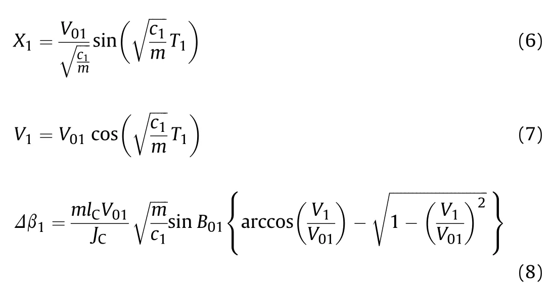
The projectile enters the tunneling sub-stage only after the complete initial cratering. In other words, if the projectile is only able to accomplish an incomplete initial cratering,it will skip over the tunneling sub-stage and enter the shear plugging sub-stage directly. In the tunneling sub-stage, the lateral resistance is symmetric, which leads to Ft2=0 and MC(Ft2)=0. Thus, the projectile moves forward in a straight line under the axial resistance Fn2that can be estimated by the following empirical formula [2,29].
where R and ρ are the target strength parameter and density of the concrete target, N* is the geometric factor of the projectile nose.
At the initial time of the tunneling sub-stage t=T1,which is also the end time of the initial cratering sub-stage,the initial trajectory distance of the second sub-stage X02=x2(T1)=0 and the projectile velocity V02=v2(T1)=V1.Similarly as done for the first sub-stage,at the end time of this sub-stage t=T2, we define the end trajectory distance, the end projectile velocity and the end attitude angle of the second sub-stage as X2=x2(T2),V2=v2(T2)and В2=β2(T2)=В1,respectively. Obviously, the second attitude deflection angle Δβ2=В2-В1=0. Substituting Eq. (10) into Eq. (1) for the second sub-stage and then integrating the resulted differential equation,X2can be derived as
The tunnel formed in this stage will impede the lateral motion of the projectile and the attitude deflection in the shear plugging substage in a way, which is called the clamping mechanism of the tunneling sub-stage. If the tunnel is long enough to impede the lateral motion of the projectile completely, the attitude deflection in the shear plugging sub-stage can be negligible, which is called here as the complete clamping mechanism.Contrarily,if the tunnel is not long enough, the attitude deflection of the projectile in the shear plugging sub-stage will depend on the tunnel length, which is called as the incomplete clamping mechanism.
2.1.3. Shear plugging sub-stage
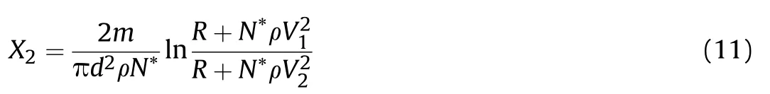
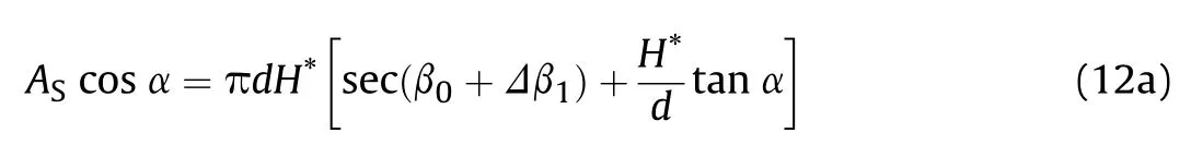
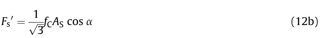
According to the experimental observation of symmetric damaged areas on the rear surfaces of concrete targets,as shown in Fig. 5 [7,13], a symmetric cone-shaped plug is assumed in this paper, whose central axis is coincident with the normal direction of the target.The cone crater formed in the shear plugging sub-stage is shown as Fig. 6(a), which is different from the asymmetric oblique-crossed cone crater proposed by Chen et al. (see Fig. 6(b))[3].
The geometric parameters of the symmetric cone crater are shown in Fig. 7, where H* is the plug’s thickness, the cone slope angle α(i.e.the acute angle between the central axis and the conical edge of the plug)is taken to be 66.1°[26],and the shear surface area is As=πl(R + r). Using the relations l2= (R-r)2+ H*2, r=d/2 s(β0+Δβ1) and R=r + H*tanα, there is
In view of von-Mises failure criterion, the plug occurs once its shear stress τfreaches the failure stress of concrete with τf=■■■■.At that moment,the shear force of the plug=τfAs,where Asis the shear surface area.As the critical forceis the projection of Fτ′along the axis of plug and satisfies=·cosα,Eq.(12b)can be obtained as
By using the geometric relations as shown in Fig.8 as well as the Newton’s third law, the axial resistance acted on the projectile is Fns=Fs·sec(β0+Δβ1)=·sec(β0+Δβ1). Therefore, with Eq. (12b),at the initial time of the shear plugging sub-stage t=T2, the axial resistance Fnscan be written as
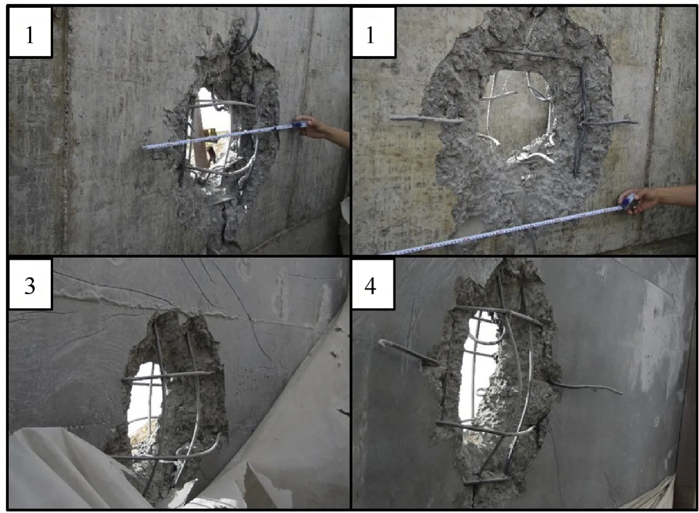
Fig. 5. Photographs of damaged areas on the rear surfaces of concrete targets in oblique perforation experiments [7,13].
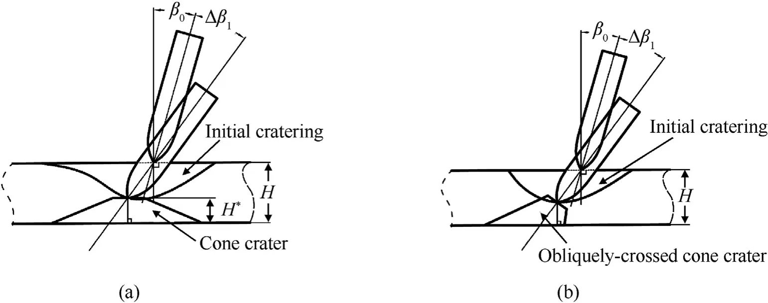
Fig. 6. (a) Symmetric cone crater proposed in this study; (b) Asymmetric oblique-crossed cone crater [3].
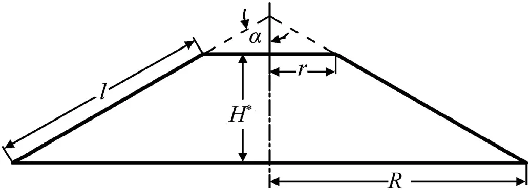
Fig. 7. Geometric parameters of the symmetric cone crater.
If it enters the shear plugging sub-stage after an incomplete initial cratering, the projectile will deflect again with the opposite direction of the initial cratering sub-stage. Referring to Chen et al.[3], in this sub-stage, with the motion of the projectile, the axial resistance Fn3can be assumed to decrease linearly from Fnsto zero as shown by Eq.(14a),and there exists a relationship between the lateral resistance Ft3and the axial resistance Fn3as shown by Eq.(14b). It is assumed that the acting point of Ft3moves gradually to the projectile centroid from the nose tip and the torque arm l=lCx3(t) decreases linearly from lC. Therefore, the axial resistance Fn3and the lateral resistance Ft3are given as
where c2is the resistance constant in the shear plugging sub-stage.
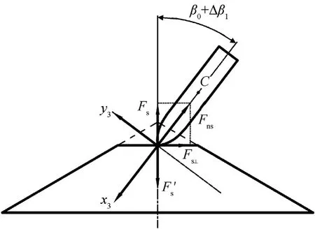
Fig. 8. The critical force of the plug at the initial time of the shear plugging substage.
At the initial time of the shear plugging sub-stage t=T2, the initial trajectory distance X03=x3(T2)=0, the initial projectile velocity V03=v3(T2)=V2, the initial angular velocity Ω03=ω3(T2)=0 and the initial attitude angle B03=β3(T2)=В2=В1=β0+ Δβ1. Substituting Eq. (14) into Eq. (1)leads to the initial-value problems for x3(t) and β3(t), respectively.Solving the initial-value problems under the initial conditions, the trajectory distance x3(t), the projectile velocity v3(t), the attitude angle β3(t), the angular velocity ω3(t)=dβ3(t)/dt and the acceleration a3(t)=dv3(t)/dt of the projectile during the third sub-stage can be obtained as
The shear plugging sub-stage is finished at the time t=T3when the plug separates from the projectile,and from then on,there is no longer action between them(the re-contact after separation is not taken into account)and the acceleration of the projectile vanishes.Similarly,we denote the end trajectory distance,the end projectile velocity, the end angular velocity, the end attitude angle and the end attitude deflection angle of the third sub-stage as X3=x3(T3),V3=v3(T3),Ω3=ω3(T3),В3=β3(T3)and Δβ3=В3-В03,respectively.Thus,from Eqs.(15)-(18), we get
where the resistance constant c2is unknown and needs to be determined as well.
As the analyses presented above are focused on each sub-stage independently, the continuous conditions between the sub-stages are still required. However, referring to Chen et al. [3], the oblique perforations of a thin target and a thick target are composed of different sub-stages. Therefore, for the concrete targets with different thickness,the continuous conditions are also different and their oblique perforation processes should be considered respectively.
Chen et al.[3]have divided the target thickness into two classes according to the trajectory distance in the initial cratering substage, namely, the thin and the thick concrete targets. However, It is insufficient while the attitude deflection in the shear plugging sub-stage as well as the clamping mechanism of the tunneling substage are taken into account. Therefore, this paper classifies the target thickness into three classes,among which the medium target between the thin and the thick targets is newly proposed, and the attitude deflection angle Δβrwill be investigated respectively for each class with their individual characteristics and continuous conditions.
For a thin concrete target,referring to Chen et al.[3],its oblique perforation consists of only two sub-stages, i.e. an incomplete initial cratering and a shear plugging sub-stages. That is, the attitude deflection angle in a thin target is Δβr=Δβ1+Δβ3(see Fig.10).
While the target thickness reaches up to a certain value, a completed initial cratering sub-stage will be accomplished and a tunneling sub-stage will appear.At this moment,we define that the target transforms into a medium one.Thus,the oblique perforation of a medium concrete target is defined to be composed of three sub-stages,i.e.a complete initial cratering,a tunneling and a shear plugging sub-stages, but among which the tunnel length X2is limited with just the incomplete clamping mechanism.That is,the attitude deflection angle in a medium target is Δβr=Δβ1+Δβ3(X2)(see Fig.11),in which the quantitative description of the incomplete clamping mechanism of the tunneling sub-stage need to be dealt with.
When the tunnel length keeps increasing with the target thickness to a certain value, the attitude deflection in the shear plugging sub-stage will be impeded completely.At this moment,it is defined that the target transforms into a thick one.Therefore,the oblique perforation of a thick concrete target is also comprised of three sub-stages,i.e.a complete initial cratering,a tunneling and a shear plugging sub-stages, among which the large enough tunnel length X2with the complete clamping mechanism leads to Δβ3=0.That is, the attitude deflection angle in a thick target is Δβr=Δβ1(see Fig. 9).
2.2. Analyses of concrete targets with different thickness
2.2.1. Thick target
The attitude deflection in oblique perforation of a thick concrete target is depicted as shown in Fig. 9. At the end time of the initial cratering sub-stage t=T1, which is also the initial time of the tunneling sub-stage, the axial resistance satisfies Fn1=Fn2at this moment,thus we have
Solving Eqs. (6)-(9) and (24) simultaneously, the end time T1,the end projectile velocity V1and the end attitude deflection angle Δβ1of the initial cratering sub-stage as well as the resistance constant c1can be obtained as
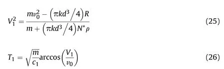
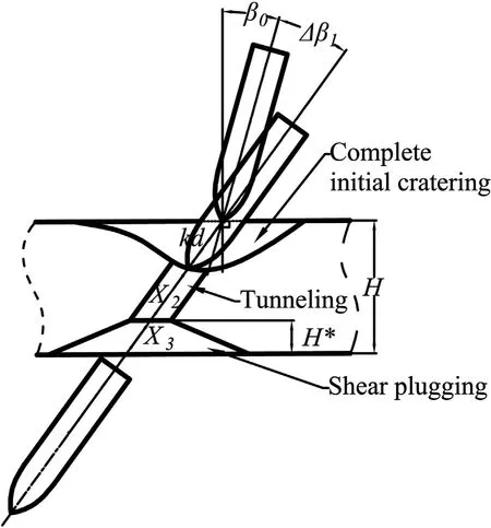
Fig. 9. Attitude deflection in oblique perforation of a thick concrete target.
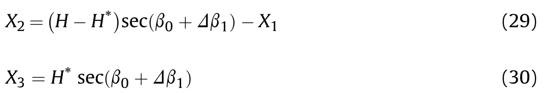
From the geometric relation as shown in Fig. 9, the end trajectory distance in the tunneling sub-stage X2and that in the shear plugging sub-stage X3satisfy, respectively,
Moreover,as the end time of the tunneling sub-stage is just the initial time of the shear plugging sub-stage, the axial resistance satisfies Fn2=Fn3at this moment. Substituting Eqs. (10) and (13)into them, one has
Therefore,X2and X3,the end projectile velocities V2and V3,the end time of the shear plugging sub-stage T3,the resistance constant c2and the plug thickness H*can be obtained respectively by solving Eqs.(11), (19)-(21) and (29)-(31) simultaneously, which Eq. (11) is approximated simply by the first order Taylor expansion of the logarithm term.
2.2.2. Thin target
The attitude deflection in oblique perforation of a thin concrete target is shown in Fig.10. Similarity, at the end time of the initial cratering sub-stage, which is also the initial time of the shear plugging sub-stage, the axial resistance satisfies Fn1=Fn3at this moment. Thus from Eqs. (2a) and (13), there is
Moreover, as shown in Fig.9, the end trajectory distance of the initial cratering sub-stage X1and that of the shear plugging substage X3can be written as
As the resistance constant c1given by Eq. (28) is only determined by the geometric and the material parameters of the projectile and the target, it is independent of the trajectory distance during the initial cratering sub-stage and the target thickness.Therefore, Eq. (28) is also adapted for the incomplete initial cratering in the oblique perforation of the thin concrete target [3].Solving Eqs.(6)-(8),(19)-(23)and(32)-(34)simultaneously,the end time of the initial cratering sub-stage T1and the shear plugging sub-stage T3, the end trajectory distances X1and X3, the end projectile velocities V1and V3, the end attitude deflection angles Δβ1and Δβ3,the end angular velocity Ω3,the resistance constant c2and the plug thickness H* can be obtained.
2.2.3. Medium target
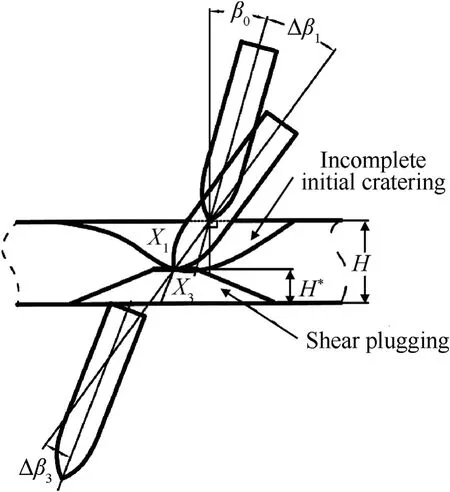
Fig.10. Attitude deflection in oblique perforation of a thin concrete target.
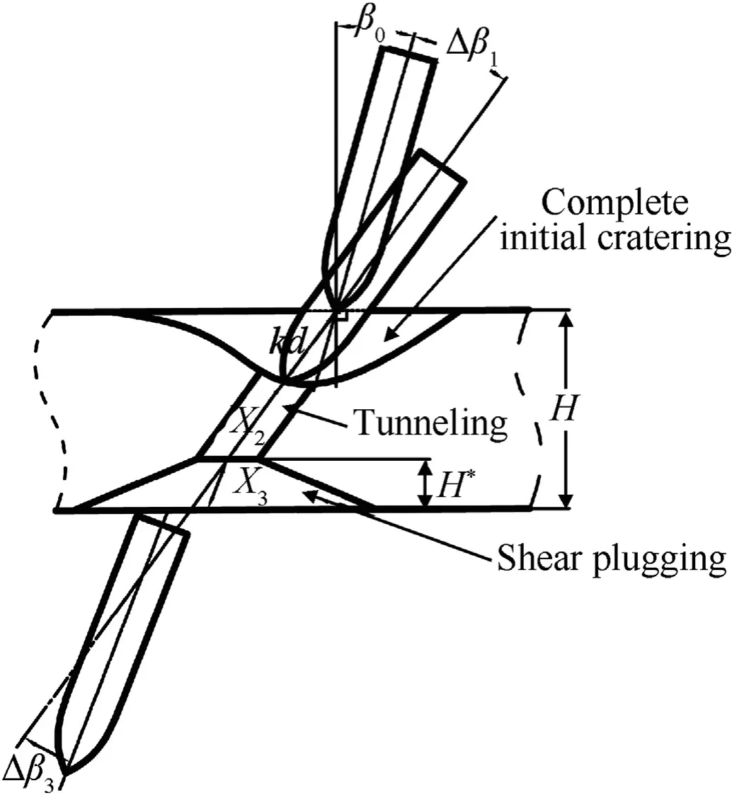
Fig.11. Attitude deflection in oblique perforation of a medium concrete target.
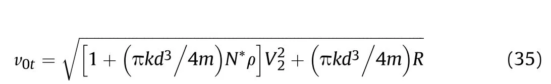
The attitude deflection in oblique perforation of a medium concrete target is shown in Fig. 11. The analysis of the complete initial cratering and the tunneling sub-stages for the medium target is the same as that for the thick target,by which the end projectile velocity V2and the end trajectory distance X2at the end time of the tunneling sub-stage can be obtained. In order to determine the attitude deflection angle and the angular velocity in the shear plugging sub-stage affected by the tunneling sub-stage,an oblique perforation process of a fictitious thin concrete target is assumed to consist of a complete initial cratering and a shear plugging substages, in which we denote the initial impact velocity as v0tand the projectile velocity at the end time of the complete initial cratering sub-stage as V1t=V2.Thus,using Eq.(25),v0tcan be obtained as
Moreover,to describe the effects of the tunnel length X2on the attitude deflection angle Δβ3, a coefficient δxis introduced as
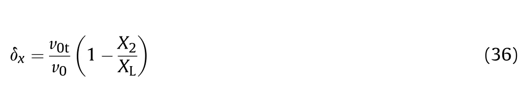
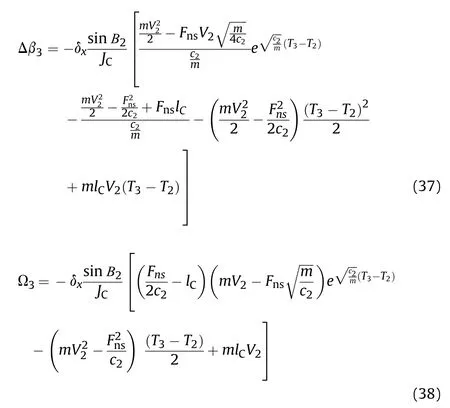
where XLis the minimum tunnel length to make Δβ3=0. Empirically, XL=2d for the projectiles with the ratio of the length to the diameter larger than 4. Using Eqs. (22) and (23), the attitude deflection angle Δβ3and the end angular velocity Ω3in the oblique perforation of the medium concrete target can be obtained as follows
2.3. Determination of classes for concrete targets
As aforementioned, the tunneling sub-stage only follows a complete initial cratering sub-stage. Thus the existence of the tunneling sub-stage can be used to distinguish a thin concrete target from a medium or a thick concrete target. A critical target thickness HLis then introduced as the minimum thickness of the target that consists of a complete initial cratering and a shear plugging sub-stages but without a tunneling sub-stage,as shown in Fig.12. Therefore, a concrete target with the thickness H less than HLis defined as a thin concrete target,and,vice versa,either a thick or a medium target.

Fig. 12. Attitude deflection in the oblique perforation of a concrete target with the critical thickness HL.
It can be seen from Fig.12 that the critical target thickness HLcan be written as

At the end time of the complete initial cratering sub-stage, the end projectile velocity V1L, the end attitude deflection angle Δβ1Land the resistance constant c1can be obtained from Eqs.(25),(27)and(28).Moreover,as the end time of the complete initial cratering sub-stage is also the initial time of the shear plugging sub-stage,so that Fn1=Fn3at this moment. By virtue of Eqs. (2a) and (13),Δβ1Land H*Lcan be solved,and then the critical target thickness HLcan be derived from Eq. (39).
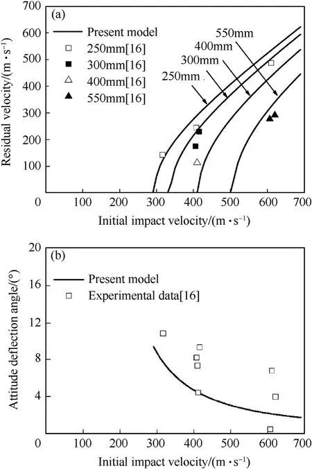
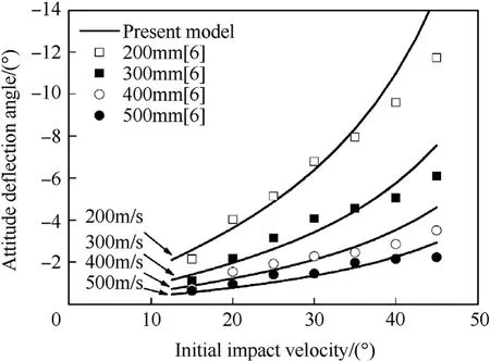
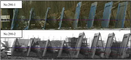
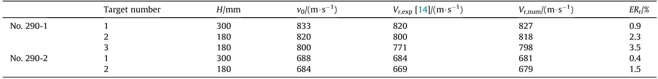
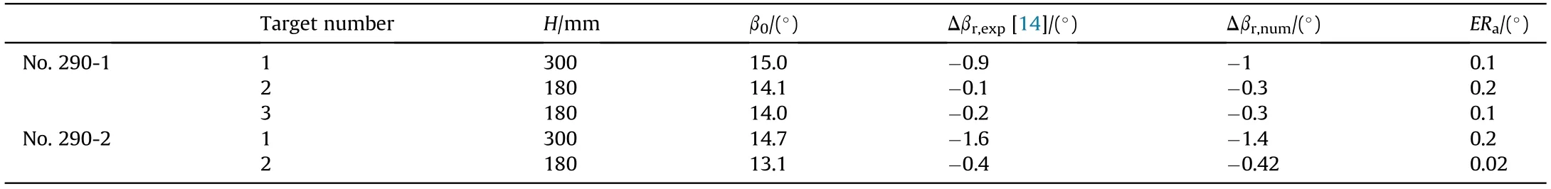
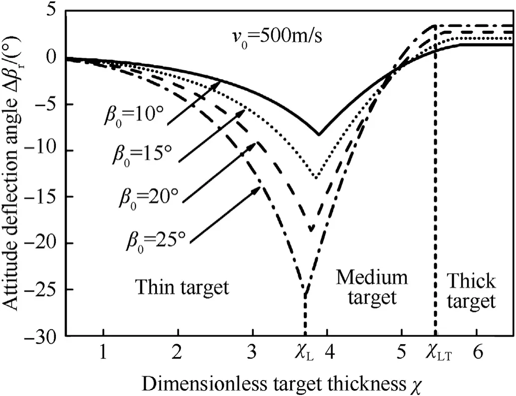
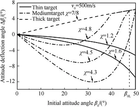
As XLis the minimum tunnel length to impede completely the attitude deflection in the shear plugging sub-stage (to make Δβ3=0), it can be used to distinguish a medium concrete target from a thick target. Therefore, a concrete target with the tunnel length X2less than XL(0 The perforation model is used and the numerical results are compared with the experimental data of the oblique perforation of both thick and thin concrete targets,as well as the simulated results of the oblique perforation of thin concrete targets[6,14,16]. In the oblique perforation experiments of thick concrete targets reported by Fan et al.[16],for the tested ogive-nose projectiles,the mass m=3.64 kg,the diameter d=50 mm,the caliber-radius-head CRH=3, and the inertia moment JC=0.018 kg m2. For the tested thick targets, the compressive strength fc=42 MPa, the density ρ=2280 kg/m3, and the target thickness H=250 mm, 300 mm,400 mm,550 mm,respectively.With the same initial attitude angle β0=30°, the experimental data and the numerical results of the residual velocity (i.e. the projectile velocity at the last time of perforation)and the attitude deflection angle are shown in Fig.13. In the numerical simulations of the oblique perforation of thin concrete targets that investigated by LS-DYNA software and reported by Liu et al. [6], the mass of the numerical ogive-nose projectile is m=100 kg, the diameter d=189 mm, the length L=1050 mm, CRH=3.3, and the inertia moment JC=9.15 kg m2.For the numerical thin targets, the compressive strength fc=30 MPa, the density ρ=2500 kg/m3, and the target thickness H=180 mm.The initial attitude angle β0varies from 15°to 45°and the initial impact velocity v0varies from 200 m/s to 500 m/s. The simulated results and the numerical results of the attitude deflection angle are shown in Fig. 14, which the negative attitude deflection angles indicate the projectiles deflect with decreasing attitude angle. In the two oblique perforation experiments of multilayered thin concrete targets performed by Ma et al. [14], for the tested truncated-ogive-nose projectiles, the mass m=290 kg, the diameter d=250 mm, CRH=1.56, and the inertia moment JC=34.53 kg m2. For the tested thin targets, the compressive strength fc=46 MPa, the density ρ=2500 kg/m3, the target thicknesses of the first layers are both 300 mm while others are 180 mm,and the target spacing is 3.5 m.The initial impact velocities and the initial attitude angles of the two tests (numbered No.290-1 and No.290-2) are v0=833 m/s, β0=15°and v0=688 m/s, β0=14.7°,respectively. There were no attack angles when the projectiles impacted on the first layers of targets. Fig. 13. The experimental data and the numerical results of the oblique perforation experiments of thick concrete targets[16]:(a)residual velocity;(b)attitude deflection angle. Fig. 14. The simulated results and the numerical results of the oblique perforation simulations of thin concrete targets [6]. The ballistic deflections of the two tests recorded by a High Speed Photograph System are shown in Fig.15 [14], in which the blue lines are the projectile axes when they impacted on the first layers of targets,the purple and the red lines are the connection of the impacting points on each layer of targets during the penetration process. These observations indicate that the projectiles deflected with decreasing attitude angle during the penetration process. As the perforation processes of the first two or three layers of targets are less affected by the attack angles,only them are calculated.Both the experimental data and the numerical results of the residual velocity Vrand the attitude deflection angle Δβrare listed in Table 1 and Table 2,respectively,in which the errors are defined as ERr=|Vr,exp - Vr,num|/|Vr,exp|×100% and ERa=|Δβr,exp- Δβr,num|,respectively. As shown in Fig.13,the prediction of the perforation model is in good agreement with the experimental data for the thick concrete targets, which indicates that the inertia moment JCis effective in describing the attitude deflection during the initial cratering substage. Moreover, it can also be found from Fig.14, Tables 1 and 2 that considering the attitude deflection during the shear plugging sub-stage and introducing the corresponding deflection mechanism make it possible to describe the phenomena in the oblique perforation of thin concrete targets, which the residual attitude angle is less than the initial attitude angle and the penetration path of the projectile tends to be the shortest path,i.e.along the normal direction of the target. With the geometric and the material parameters of the numerical projectile(m=100 kg)and the concrete target given by Liu et al. [6], the variations of the attitude deflection angle Δβrversus the dimensionless target thickness χ (= H/d), the initial attitude angle β0and the initial impact velocity v0are investigated respectively.The numerical results are shown in Figs.16-18,respectively.The signs of Δβrrepresent the deflection directions,i.e.Δβr>0 indicates that the projectile deflects with increasing attitude angle while Δβr< 0 indicates the decreasing attitude angle. Moreover,while the signs of Δβ1(>0) and Δβ3(<0) both represent the deflection directions, the increase of Δβ1and the decrease of Δβ3indicate a more violent attitude deflection in the initial cratering sub-stage and the shear plugging sub-stage, respectively. The variation of Δβrversus χ for four initial attitude angles β0=10°, 15°, 20°, 25°under the same initial impact velocity v0=500 m/s are shown in Fig.16. It can be seen clearly that there exist two critical target thicknesses χLand χLTon each curve,cross which the class of the target will transform and the attitude deflection angle will vary versus χ in a different way.Both of them decrease with the increase of β0. Typically, the two critical target thicknesses χL=3.84, χLT=5.74 for β0=15°. Moreover, it can be found that,with the increase of χ,Δβrdecreases in the thin target,but increases in the medium target and then keeps constant in the thick target. In the medium target, the attitude deflection angle Δβ1of the complete initial cratering sub-stage remains unchanged with the variation of χ. However, the increase of the tunnel length X2,resulting from the increase of χ, and the enhanced clamping mechanism will alleviate the attitude deflection in the shear plugging sub-stage, so that Δβ3increases with χ. Therefore, the attitude deflection angle Δβrincreases with χ in the medium target. The variation of Δβrversus β0for seven target thicknesses χ=1.2,1.6(thin targets),4.3,4.5,4.8(medium targets),7.0 and 8.0(thick targets) under the same initial impact velocity v0=500 m/s are shown in Fig. 17. It is found that with the increase of β0, Δβrdecreases in the thin target and increases in the thick target,which both indicate a more violent attitude deflection.But in the medium target, Δβrdecreases first and then increases. Moreover, as shown in Fig. 17, there exists a critical initial attitude angle β0Lon each curve for the medium targets, and,for β0>β0L,the medium target will transform into a thick target. Typically, the critical initial attitude angle β0L=47.5°for χ=4.5. Fig.15. The ballistic deflections recorded in the oblique perforation experiments of multilayered thin concrete targets [14]. Table 1 The experimental data and the numerical results of the residual velocity Vr in the oblique perforation experiments of multilayered thin concrete targets. Table 2 The experimental data and the numerical results of the attitude deflection angle Δβr in the oblique perforation experiments of multilayered thin concrete targets. Fig.16. Variation of the attitude deflection angle Δβr versus the dimensionless target thickness χ in the oblique perforation of concrete targets. In the medium target,the increased β0results in the increase of both Δβ1and X2as well as the decrease of Δβ3, however, the increased X2leads contrarily to the increase of Δβ3. When β0is small and the clamping mechanism under a small X2is not significant,the variation of Δβ3is dominated by β0.But with the increase of β0,the increased X2will gradually dominate the variation of Δβ3.Therefore, Δβ3as well as Δβrfirst decreases and then increases in the medium target. When β0increases to β0L, X2becomes large enough such that Δβ3increases to zero, and then the medium target transforms into the thick one. Fig.17. Variation of the attitude deflection angle Δβr versus the initial attitude angle β0 in the oblique perforation of concrete targets. Fig.18. Variation of the attitude deflection angle Δβr versus the initial impact velocity v0 in the oblique perforation of concrete targets. The variation of Δβrversus v0for six target thicknesses χ=2.2,2.8 (thin targets), 5.1, 5.4 (medium targets), 7.0 and 8.0 (thick targets) under the same initial attitude angle β0=15°are shown in Fig.18.It is found that with the increase of v0,Δβrincreases in the thin target but decreases in the thick target, which both indicate that the attitude deflection is alleviated. However, in the medium targets, the variation of Δβrdepends on the target thickness. For example, for a thinner medium target (χ=5.1), Δβrincreases monotonously, while, for a thicker medium target (χ=5.4), Δβrincreases first and then decreases. In the medium target, both Δβ1and X2will decrease with v0.Similarly, while the increased v0leads to the increase of Δβ3, the decreased X2leads to the decrease of Δβ3contrarily. For a thinner medium target(χ=5.1),the negligible clamping mechanism under a small X2dominates the variation of Δβ3with v0, so that the attitude deflection angle Δβrincreases monotonously.However,for a thicker medium target (χ=5.4), the remarkable clamping mechanism under a larger X2leads to that the variation of Δβ3is gradually changed into a X2-dominated one, so that Δβ3as well as the attitude deflection angle Δβrfirst increase and then decrease with v0. In a word,the attitude deflection in a medium concrete target is under the deflection mechanisms of both the initial cratering and the shear plugging sub-stages as well as the incomplete clamping mechanism of the tunneling sub-stage. The quantitative description of the incomplete clamping mechanism of the tunneling substage can be realized by the introduced coefficient δx, and the variations of the attitude deflection angle Δβrversus different initial conditions can be predicted for a medium target. A perforation model has been developed to predict the attitude deflection in the oblique perforation of concrete targets by a rigid projectile,with broader applications,and the numerical results are in good agreement with a series of experimental data and simulated results. Some conclusions can be drawn out as follows. (1) The inertial moment of a projectile is an important parameter in predicting the time history of the attitude deflection angle during the initial cratering sub-stage, by which, the perforation model can predict accurately the attitude deflection in the oblique perforation of thick concrete targets. (2) The shape revision of the plug formed on the rear surface of the target is reasonable.Moreover,the introduced deflection mechanism in the shear plugging sub-stage is of great significance in describing the attitude deflection in the oblique perforation of thin concrete targets, by which, the phenomenon that the residual attitude angle is less than the initial attitude angle can be predicted well. (3) The incomplete clamping mechanism during the tunneling sub-stage can be described quantitatively by an introduced coefficient δx,by which the attitude deflection in the oblique perforation of medium concrete targets can be predicted well. (4) The classification for the concrete targets in the oblique perforation is necessary to predict well the attitude deflection angle, which can be realized by defining the critical target thickness HLand the critical tunnel length XL.Thus,the targets with the thickness less than HLbelong to the thin targets,that with the thickness larger than HLbut the tunnel length larger than XLbelong to the thick targets,and the rest belong to the medium targets. No conflict of interest exits in the submission of this manuscript. This work was supported by the National Natural Science Foundation of China [grant numbers 11521062].3. Numerical results and discussions
4. Conclusion
Declaration of competing interest
Acknowledgments
杂志排行

Defence Technology的其它文章
- Statistical variability and fragility assessment of ballistic perforation of steel plates for 7.62 mm AP ammunition
- Texture evaluation in AZ31/AZ31 multilayer and AZ31/AA5068 laminar composite during accumulative roll bonding
- Local blast wave interaction with tire structure
- Research and development of training pistols for laser shooting simulation system
- Summed volume region selection based three-dimensional automatic target recognition for airborne LIDAR
- A novel noise reduction technique for underwater acoustic signals based on complete ensemble empirical mode decomposition with adaptive noise, minimum mean square variance criterion and least mean square adaptive filter