An air cavity method for increasing the underwater acoustic targets strength of corner reflector
2020-05-23YiLuoXinChenDaweiXiaoWudiWenTaotaoXie
Yi Luo, Xin Chen, Da-wei Xiao, Wu-di Wen, Tao-tao Xie
Dept. of Weaponry Eng, Naval University of Engineering, Wuhan 430033, China
Keywords:Underwater corner reflector Acoustic target strength Air cavity Acoustic impedance mismatch
ABSTRACT In order to improve the underwater acoustic target strength of corner reflectors, according to the principle of acoustic impedance mismatch of the boundary layer, the method of using air cavity to increase the underwater acoustic target strength of corner reflectors is proposed. The acoustic reflection coefficients of underwater air layer and single layer metal sheet are calculated and compared.The results show that the reflection coefficient of single layer metal sheet is greatly affected by frequency and incidence angle,and the reflection coefficient of air layer in water is large and little affected by frequency and incidence angle.On this basis,a new kind of airfilled cavity corner reflector is designed.The acoustic scattering characteristics of underwater airfilled cavity corner reflector are calculated cumulatively, and the results are compared with the monolayer metal sheet corner reflector. The simulation results show that the acoustic reflection effect of the airfilled cavity corner reflector is better. In order to verify the correctness of the method,the test was carried out in the silencing tank.The experimental results show that the simulation results are in good agreement with the experimental results, and the airfilled cavity can improve on acoustic reflection performance of the underwater corner reflector.
1. Introduction
The corner reflector has the advantages of strong reflection ability, simple structure and convenient use, and its schematic diagram is shown in Fig.1.Three metal plates connected vertically to each other, and the shape of the metal plate can be triangular,square, etc. It is usually used to simulate the electromagnetic reflection characteristics of objects on the ground [1]. Using underwater corner reflector to simulate the acoustic reflection characteristics of warships is a new technical approach to counter active sonar detection [2,3]. A number of small underwater corner reflectors can be used to simulate the acoustic echo bright spots of warships. For example, the length characteristics of warships are relatively obvious,and multiple small underwater corner reflectors can be used in series to simulate the longitudinal acoustic reflection characteristics of warships.
At present, there is little research on underwater corner reflector,and the research of underwater corner reflector is mainly monolayer metal corner reflector [3,4]. However, the acoustic performance of underwater monolayer metal corner reflectors are not ideal.The results show that[4],the underwater thin metal plate corner reflector has small target strength, small scattering width and strong frequency characteristic.When it is used to simulate the target strength of warships, the size is too large, which is not suitable for engineering application.
In order to improve the target strength of underwater corner reflector, the acoustic impedance between water and reflection layers should be mismatched. Because of the serious mismatch of the characteristic impedance between air and water, in this paper,the method is proposed to improve the acoustic reflection effect of underwater corner reflector by using underwater air layer.

Fig.1. Schematic diagram of corner reflector.
The underwater corner reflector is a thin-walled structure immersed in water. When calculating its acoustic scattering characteristics, it is necessary to consider the fluid medium and its important influence on the vibration of the structure [5,6]. It is an important trend to solve the acoustic radiation or scattering problem of underwater elastic target by coupling the indirect boundary element method with the finite element method[7,8].In addition, the corner reflector is a “concave” structure, and the contribution of multiple scattering waves can not be ignored in the calculation of its scattered sound field [9]. The software SYSNOISE will consider the reflection, diffraction and refraction of sound when simulating the acoustics of the target,which is convenient to calculate the scattering acoustics field of concave structure [10].Therefore, the scattering acoustics field of underwater corner reflector is solved by the coupling indirect boundary element method of finite element method, and the acoustic scattering characteristics of underwater air cavity corner reflector are simulated and analyzed by using finite element software ANSYS and acoustic software SYSNOISE. The scattering characteristics of monolayer metal plate corner reflector and air cavity corner reflector are compared and the results are verified by experiments.
2. Methods to improve the target strength
Flat plate is the foundation of underwater corner reflector, and its acoustic reflection coefficient is the main factor that affects the target strength.
In order to improve the acoustic reflection coefficient of the plate,the acoustic impedance of the plate medium and the acoustic impedance of water should be mismatched as much as possible.The acoustic impedance of air layer in water is much smaller than that of steel plate due to the low density and sound velocity,so the air layer in water can be used as a good antiacoustic medium. The reflection coefficients of infinite sheet metal and air layer in water are compared respectively.
2.1. Acoustic reflection performance of sheet metal
Fig.2 shows the sound wave propagating through the thin plate.h1 is the thickness of the thin plate;p0,ptis the incident wave and the transmission wave;pris the reflected wave, and θ is the angle between the incident wave and thezaxis.
When plane wave is incident on a thin plate, two forms of vibration, namely bending vibration and symmetric vibration, are activated. For a plate whose thickness is much smaller than the acoustic wavelength in a material,it can be regarded as a thin plate to calculate its reflection coefficient.

Fig. 2. Schematic diagram of propagation of sound wave through thin plate.

In the formulaula,Ais the reflection coefficient;Zis the impedance of bending vibration of thin plate;Znpis the impedance of symmetrical vibration of thin plate;Z0= ρc/cosθ is the normal acoustic impedance; ρ is the density of water;cis the velocity of sound in water.
In fact, for any sheet metal, theZnpis much greater thanZ0in almost all incident ranges, and the reflection coefficient can be calculated by using an approximate formula that does not consider the longitudinal wave.

The impedance of bending vibrationZcan be derived from the vibration equation of thin plate. Owing toso

Suppose that: ρ=1000 kg/m3;c=1480 m/s; σ=0.29;E=216 GPa;ρM=7800 kg/m3.
Fig.3(a)and(b)are reflection coefficient diagram of a thin plate with thickness of 5 mm and 10 mm at full incident angle, respectively.It can be seen that the reflection coefficient of the steel plate increases with the increase of frequency and decreases with the increase of incidence angle (vertical incidence is 0°), and the reflection coefficient increases with the increase of thickness.Therefore,although a certain thickness of steel plate can be used to make a corner reflector, its reflection coefficient is greatly affected by the incident angle and frequency, and is very heavy, so it is not convenient for engineering application. For example, in order to ensure good reflection capability,the thickness of the steel plate of the corner reflector should reach 10 mm, so that the mass of one corner reflector reaches 29.25 kg (the length of side is 0.5 m). For convenient use, the individual mass shall be less than 10 kg.

Fig. 4. Schematic diagram of propagation of sound wave through air layer.
2.2. Acoustic reflection performance of air layer in water
Fig. 4 shows the propagation of sound waves through the air layer in water.his the thickness of the air layer;p0,ptis the incident wave and transmission wave;pris the reflection wave;p2is the refraction wave;θ is the incidence angle;θ2is the refraction angle;ρ1is the density of water;c1is the velocity of sound in water;ρ2is the density of air, andc2is the velocity of sound in air. When the plane wave incident into the air layer, it does not excite the shear wave, and the reflection coefficient can be deduced. Its reflection coefficient is

In the formulaula,P=k2hcosθ2;k2is the acoustic wave number in the air, and

If the incident angle of a plane wave does not exceed the critical angle of total internal reflection, P is a real number, so

It is considered that when the hydrostatic pressure increases to scores of atmospheric pressures, the velocity of sound in air very little change,while the density of air increases in a straight line.In the given pressure range,the density of water and sound velocity in water can be approximately considered as constants. Let the air density be 1.21 kg/m3and the velocity of sound in air be 343 m/s.The reflection coefficient of the air layer in the water under different hydrostatic pressure is calculated according to Eq. (5).
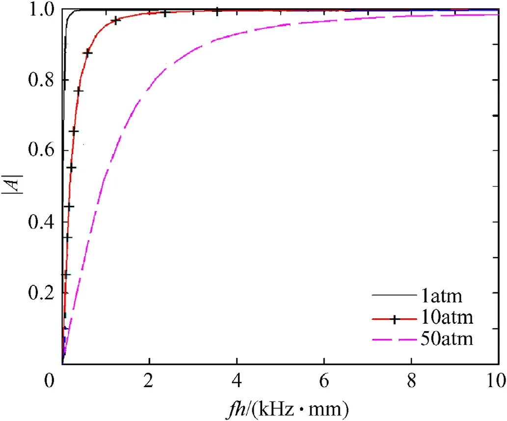
Fig. 5. Reflection coefficient of air layer under different static pressure.

Fig. 6. Reflection coefficient of air layer under different static pressure.
Fig. 5 shows the relationship between the frequency thickness product and the reflection coefficient of the air layer under different hydrostatic pressure. It can be seen from the diagram that: (1)when the static pressure is very small, the reflection coefficient of the air layer increases rapidly with the increase of the frequency thickness product of the layer, and the reflection coefficient is fast approaching to 1; (2) when the static pressure increases, the characteristic impedance ratio of air to water increases, and the reflection coefficient of air layer decreases,but the change trend is slower.
Fig. 6(a) and (b) show the variation of the reflection coefficient of the air layer with the incident frequency and the incident angle when the purified water pressure is 10 and 50 standard atmospheric pressure,respectively.Here,the thickness of the air layer at a standard atmospheric pressure is 20 mm, and only the air layer thickness and the density linear change are caused when the pressure is increased.
It can be seen from the diagram that:(1) when the static pressure is small,the reflection coefficient of the air layer with thickness of 20 mm is almost 1 within the all range of frequency and all incidence angle;(2)when the static pressure increases,the acoustic reflection performance of the air layer decreases,and the reflection coefficient increases with the increase of the frequency and incidence angle of the incident wave, and the greater the static pressure is, the more obvious the change is.
2.3. Acoustic reflection performance of air cavities
By comparison, we can see that the underwater acoustic reflection coefficient of the air layer is larger, so the underwater acoustic corner reflector can be constructed to improve the target strength. But the reflection performance of the air layer changes with the change of static pressure. In order to ensure that the air layer in water has stable acoustic reflection performance, the airfilled cavity should be made with pressure proof structure, so that the air density does not change with the increase of hydrostatic pressure.
Therefore,the thin metal plate(1 mm thickness)is welded into a closed airfilled cavity, and a certain number of reinforcement bars are installed to enhance the strength and compression resistance of the structure.The profile of the thin steel plate with airfilled cavity is shown in Fig. 8. Because the surface metal is very thin and the reflection coefficient is very low,it can almost be used as complete permeable.
The influence of hydrostatic pressure on air density and sound velocity is neglected in calculation because of the high pressure resistance of steel airfilled cavity. Fig. 7 shows the reflection coefficient of the airfilled cavity with thickness of 20 mm at full incidence angle. It can be seen from the figure that the reflection coefficient of the air layer in almost all the ranges of 5 kHz-20 kHz is 1, which can achieve complete reflection, and there is only a depression at certain incidence frequency, and the reflection coefficient almost does not change with the incident angle. It can be seen that the airfilled cavity in water is an ideal antiacoustic structure because of its large reflection coefficient, stable performance and light weight.
3. Calculation method of acoustic scattering for underwater corner reflector
From the above calculation, it can be seen that the underwater airfilled cavity plate has the advantages of large reflection coefficient,little influence of frequency and incidence angle,and can be used to construct underwater acoustic corner reflector.
The underwater corner reflector is a thin-walled structure immersed in water. The structural finite element coupled fluid indirect boundary element method is suitable for solving the acoustic scattering problem with fluid in and out of the structure. The acoustic scattering of underwater acoustic corner reflector is calculated by this method,and the fluid-solid coupling equation of the method is deduced.

Fig. 7. Schematic diagram airfilled cavity.

Fig. 8. Relationship between reflection coefficient of air layer, frequency and angle.

Fig. 9. Geometric relationship of IBEM.
Suppose the object is in the ideal fluid; Q is any point on the structural surface S;n is the unit vector of the outer normal of the point Q;P is any point in space;rP,rQ,rAare vectors from point O to point P, Q,A respectively. Its diagram is shown in Fig. 9.
According to the wave equation, the Helmholtz equation of direct boundary element method for single frequency scattering sound field can be derived.

In the formula,pis instantaneous sound pressure;is the sound pressure of pointwhich is Green’s function;is wavenumbers;is circular frequency;is the velocity of sound in the fluid;P is the density of the fluid; vnis the normal velocity of the point Q ;is the sound pressure at point P.
Indirect boundary element method can be deduced from direct boundary element method. In the indirect boundary element method, the unknown variables are the acoustic pressure difference (double layers potential) and the sound pressure gradient difference (single layer potential) on both sides of the boundary surface. The Helmhozts integral equation of the direct boundary element method is applied to both sides of the boundary surface and the sound pressure of any field point can be obtained by subtracting the two equations


Let the boundary surface satisfy the Neumman condition and define P on the boundary. The relation between the boundary condition and the unknown variable is obtained

In the formula, v(rP) is the vibration velocity of point P. When the boundary surface is discretized, the unknown variables on the surface of the boundary element model can be represented by the unknown variables and shape functions of the nodes of the model.According to the variational principle, the general form can be deduced

In the formula,A is symmetric matrix;x is unknown variable on the surface of the boundary element model, that is,oris vector function of acoustic excitation.
For the acoustic scattering problem of underwater elastic targets, assuming that the structure damping is zero, in the physical coordinate system, the lossless coupling system equations of the finite element structure model and the indirect boundary element fluid model are as follows

After the unknown variables of the boundary surface are calculated, the sound pressure and intensity at any point in the space can be solved, and the corresponding target strength can be obtained.

4. Simulation and comparison
The scattering sound field of monolayer steel plate corner reflector and elastic airfilled cavity corner reflector is simulated by finite element software ANSYS and acoustic software SYSNOISE,and its scattering characteristics are compared and analyzed.
4.1. Target strength comparison at different frequencies
Fig.10 is the schematic diagram of plane wave incident to the dihedral corner reflectors, andlrefers to the side length of the dihedral reflector. All the side length of the dihedral reflectors are 1 m. The thickness of the monolayer sheet dihedral reflector is 5 mm、10 mm、20 mm respectively. The thickness of the surface steel plate of the airfilled cavity dihedral reflector is 1 mm and the thickness of the air layer is 20 mm The incident wave is plane wave with amplitudeA=1 Pa, and the sound source is 100 m from the target. The simulation satisfies the conditions of far field. The analysis frequency is 5 kHz-20 kHz,and the field point is located at the sound source (transceiver and receiver combination), regardless of the structural damping.
According to the above simulation conditions, the target strength curves of the airfilled cavity corner reflector and the monolayer metal plate corner reflector with thickness of 5-10-20 mm are calculated respectively. The simulation results are shown in Fig.11.
It can be seen from the diagram that:
(1). The target strength of airfilled cavity corner reflector is larger than monolayer metal plate corner reflector;
(2). The change curve of target strength of monolayer metal thin plate corner reflector has obvious frequency characteristic,and the curve varies greatly and minimally with the change of frequency. This is mainly caused by the acoustic incident wave to the surface of the elastic structure in water and excited some resonance modes of the structure.

Fig.10. Schematic diagram of plane wave incident on biplanar corner reflector.
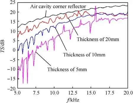
Fig. 11. Target strength of airfilled cavity dihedral reflector and monolayer sheet dihedral reflector.
(3). For the airfilled cavity corner reflector, when the frequency increases,the reflection of corner reflector mirror increases,the target strength increases first and then tends to steady,and there is no obvious frequency effect.
It is obvious that the airfilled cavity corner reflector in water has good acoustic reflection effect and decoupling effect.
4.2. Contrast of target strength with different incidence angle
The triangular thin steel plate corner reflector and triangular airfilled cavity corner reflector are selected as the research objects.The strength changes of the corner reflectors are analyzed when the acoustic wave is incident from different angles. The schematic diagram is shown in Fig.12, andlrefers to the side length of the corner reflector (1 m in paper). The thickness of monolayer steel plate corner reflector is 20 mm;the surface steel plate thickness of airfilled cavity corner reflector is 1 mm, and the thickness of air layer is 20 mm. The angle of incidence (φ =45°, θ=0°-90°, and θ =55°, φ=0°-90°)are defined respectively. The change of target strength in different frequency conditions is observed. The simulation results are shown in Figs.13 and 14.

Fig.12. Schematic diagram of plane wave incident on trihedral corner reflector.

Fig.13. Target strength of φ=45°,θ=0-90°.
It can be seen from the diagram that: (1). the target strength curve of the metal steel plate corner reflector fluctuates obviously with the incident angle, and the acoustic reflection effect is not good, while the target strength curve of the airfilled cavity corner reflector changes gently with the incident angle,and in most of the incident direction, the target strength is larger than that of the same size steel plate corner reflector, and the acoustic reflection effect is better. (2). the change trend of the target strength of the two kinds of corner reflectors is the same in different frequency conditions, and the larger the frequency is, the greater the target strength is.

Fig.14. Target strength of θ=55°,φ=0-90°.In Figs.13 and 14,(a)is metal plate corner reflector and (b) is airfilled cavity corner reflector.
At present, there is little research on underwater corner reflector.Considering the underwater application environment,the underwater corner reflector should have certain structural strength, corrosion resistance and so on; the research of underwater corner reflector is mainly metal corner reflector, Therefore the acoustic reflection effect of the corner reflector proposed in this paper is compared with that of the metal corner reflector.
5. Test verification
In order to verify the effectiveness of the proposed method and the correctness of the simulation results, two kinds of triangular corner reflectors are designed and fabricated.
(1) The corner reflector of thin steel plate is 0.5 m in length and 2 mm in thickness;
(2) The airfilled cavity corner reflector is 0.5 m in length. Its thickness of the outer layer steel plate is 1 mm, and the thickness of the inner air layer is 20 mm.

Fig.15. Schematic diagram of trial in anechoic pool.
The sound scattering was tested in a silencing tank.The incident wave is a CW pulse signal with frequency of 15 kHz and the emission period is 2 s. In order to obtain the steady state scattering target strength, the pulse width of the emission signal is set to be 1 ms.The schematic diagram of the experiment is shown in Fig.15.The distance from receiver to emitter (that isd1) is 0.5 m and the distance from receiver to corner reflector (that isd2) is 3 m. The distance from the emitter to the corner reflector is 6 times that of the receiver, so the measurement can satisfy the conditions of far field. The change curve of target strength is measured by direct method when the incidence angle of sound signal is different(φ=45°、θ=0°-90°, and θ=55°、φ=0°-90°), and the measure is taken every 3°. The test scene is shown in Fig.16.
The target strength is represented by the acoustic signal voltage value which is received by the hydrophone:

In the formula,Uiis the voltage value of incident signal;Uris the voltage value of reflection signal and its distance to the center of the target sound source is 1 m;Ubis the voltage value of target echo signal;Udis the voltage value of directness signal.

Fig.16. Scene of trial in anechoic pool.
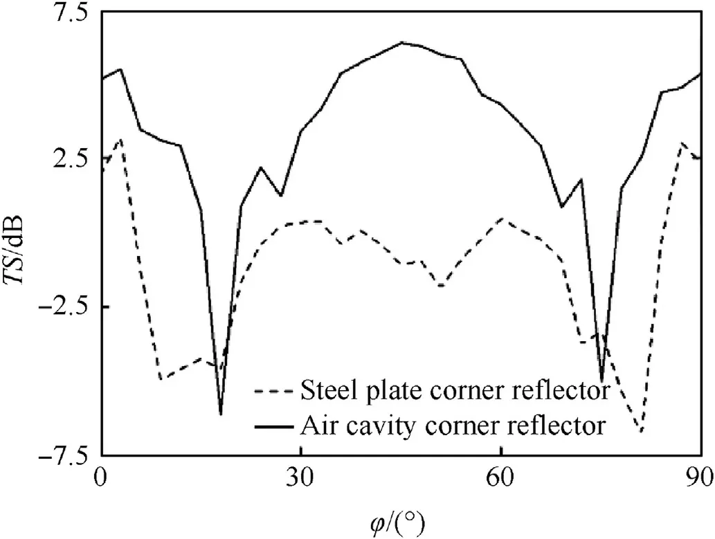
Fig.17. Experimental comparison of the target strength.
Fig. 17 is the comparison of the target strength between the airfilled cavity corner reflector and the monolayer steel plate corner reflector at the same incidence angle. It can be seen from the diagram that the target strength of the airfilled cavity corner reflector is obviously greater than that of the single layer steel plate corner reflector in most incident directions. In the vicinity of 18°and 75°,the target strength of the airfilled cavity corner reflector is smaller than that of the monolayer steel plate corner reflector.After examination,it is found that the airfilled cavity corner reflector has machining errors, and the deviation of the three vertical planes is 5°,which leads to the decrease of the target strength.Therefore,the air layer can increase the target strength of the underwater corner reflector.
Figs.18 and 19 are the comparison between the simulation results of the target strength of the triangular airfilled cavity corner reflector and the experimental results. It can be seen that two results are basically the same, thus validating the correctness of the simulation results. The effectiveness of the air cavity in increasing the target strength of the corner reflector is also proved again.There is certain warp between the experimental results and the simulation results, but within a reasonable range, and the main reason is the perpendicularity error of the reflector when the corner reflector is machined.
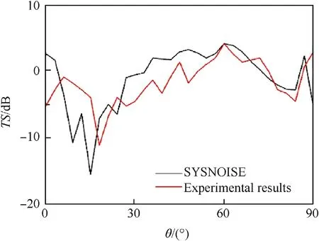
Fig.18. Target strength of φ =45°, θ=0-90°.

Fig.19. Target strength of θ=55°, φ =0-90°.
6. Conclusion
In order to improve the acoustic reflection performance of underwater corner reflector, the acoustic reflection coefficients of underwater monolayer metal plate and air layer are calculated,and a new underwater airfilled cavity corner reflector is designed. The acoustic scattering characteristics of the airfilled cavity corner reflector are calculated by using the structural finite element coupled fluid boundary element method.The simulation results are compared with the thin steel plate corner reflector,and verified by experiments. The results show that the air layer can effectively increase the underwater acoustic target strength and improve the frequency characteristics of the corner reflector.
The structure deformation of underwater airfilled cavity corner reflector will affect the acoustic reflection performance, which is not further analyzed in this paper because of the limitation of the space. In addition, the acoustic scattering characteristics of multigrid corner reflectors need further study.
杂志排行
Defence Technology的其它文章
- Defence Technology
- Enhancing the explosive characteristics of a Semtex explosive by involving admixtures of BCHMX and HMX
- Modeling and realization of real time electronic countermeasure simulation system based on SystemVue
- Numerical investigation of dynamic interaction with projectile and harmonic behaviour for T-finned machine gun barrels
- Anti-follower jamming wide gap multi-pattern frequency hopping communication method
- The prediction formula and a risk-based sensor scheduling method in target detection with guiding information
