A novel variable topology design for a multi-flexible ejection mechanism
2020-05-23HoLiuJunZhouZongliMoShiweiZhng
Ho Liu , Jun Zhou ,*, Zong-li Mo , Shi-wei Zhng
a School of Astronautics, Northwestern Polytechnical University, Xi'an, 710072, China
b School of Mechanical Engineering, Nanjing University of Science and Technology, Nanjing, 210094, China
c Luoyang Opto-Electro Technology Development Center, 471009, China
Keywords:Variable topology Gap dynamics Multi-flexible body Flexible control Ejection mechanism
ABSTRACT The airborne missile launch mechanism often subjects to significant deformations induced by the large ejection force during high-speed actuations in missile ejection process,leading to a substantial deviation of separation parameters from designed values that threats safety of the carrier. This study proposes a novel variable topology design for launch mechanism, achieved via a Prismatic-Revolute-Revolute pair(PR-R) motion formed by the structural gap with a specific direction. It enables launch mechanism variability during missile ejection process and optimizes the ejection force given by the front and back ejection arms, and greatly optimizes the separation parameters during missile ejection. The kinetics simulation analysis is conducted under working conditions of the original ejection mechanism and the novel mechanism with variable topology design, respectively. The results show that the novel variable topology design is more befitting for the launch process in terms of system safety and controllability,effectively improving the separation posture, restraining the flexible effect of the mechanism, and fulfilling the effectiveness of the design value of multi-rigid body.
1. Introduction
The embedded ejection technology of air-to-air missile is to provide the concealed shooting effect for the advanced fighter.Before the missile launching, the carrier first opens the weapon cabin door, and then the launching mechanism ejects the missile with a certain downward velocity and angular velocity, and the missile finally fires away after falling for a certain distance.During the ejection process, the safety of the missile separation is mainly associated with the separation speed and separation angular velocity of the missile, given by the launch mechanism.
In the last years,some researches on the launch safety of missile have been carried out, and some good results have been achieved,including the influence of the pneumatic flow field [1-4], the ejection dynamics of separation [5-7], and the ground test verification techniques [8], etc. Merrick et al. [1] studied the free-fall trajectory and attitude of the embedded missile under the action of airflow, and pointed out that the missile attitude changed dramatically under the influence of complex airflow, leading to hidden dangers to the carrier safety. By utilizing the overlapping grid technology,Zhang et al.[3]conducted a numerical simulation comparison between the external hanging delivery and the embedded launching,and obtained the falling rules of the external hanging delivery and the embedded launching body under the conditions of subsonic velocity and supersonic velocity. It was pointed out that the initial downward angular velocity of the missile was crucial for the purpose of the launching safety of the embedded missile. Liu et al. [4] analyzed the impact of overload centrifugal force generated by large maneuvering of aircraft on the ejection separation parameters of air-to-air missile based on Lagrange dynamic equation. Yan et al. [6] utilized the improved delayed separation vortex-simulation method combined with the dynamic grid technology to carry out unsteady calculation of the three-dimensional flow field in the process of internal ejection separation, and obtained the influence law of different inlet Mach number, projectile launching velocity, initial angular velocity and other parameters on the trajectory of projectile body.Based on the rigid-flexible coupling multi-body dynamics model, Wang [7]studied the influence of structural parameters of the air-to-air missile embedded catapult launching system on its catapult separation parameters, and pointed out that the initial angular velocity of the missile was “rise” due to the flexibility of the mechanism during the catapult launching.
In order to ensure the launch safety, the embedded missile needs a downward velocity and downward angular velocity relative to the carrier. However, due to the large ejection force and the strictly lightweight design, the components of the ejection mechanism suffer from serious flexible deformation,resulting in critical deviation of the angular velocity of the missile from the designed value, even leading to the “head-up” problem which threats the safety of the carrier. Currently, there are two common methods to solve the flexible deformation problem for high-speed motion mechanism:
1) Increase the stiffness of the mechanism components. It can reduce the flexibility deformation effect of the mechanism. But it also significantly increases the weight and the volume of the ejection mechanism, which is conflict with the lightweight design requirement.
2) Passive control method using damping layer [9,10] and active control method based on piezoelectric actuation [11-13]. The airborne missile catapult launcher requires a stringent, lightweight and compact design with large ejection force and short actuation time (less than 0.15 s). The passive control method of damping layer and the active control method of piezoelectric actuator are difficult to be implemented due to the limited control effect and high engineering cost.
Variable topology design is a new method [14-17] used for optimizing the mechanism function.Currently,the optimization of the dynamic behavior of the flexible mechanism is rarely reported.This paper proposes a novel variable topology design to optimize the airborne missile ejection separation parameters by using the variable kinematic pair to realize the variable topological design.This method focuses on the suppression of the flexibility effect of the entire ejection mechanism instead of individual component.The variable topology design can also be used for the dynamic performance optimization of other parallel high-speed flexible actuators.
2. Dynamics model of the missile ejection based on a fixed topological launcher
The dynamics model of the missile ejection process is based on the combination of the finite element method and the multi-body dynamic Lagrange equation. Considering the complexity of the mechanism model, the mechanical components that flexible processed in finite element software(ANSYS)are assembled according to the actual motion constraint pair.
Firstly,the modal analysis of each flexible component is carried out via the finite element software(ANSYS),and the modal neutral file is generated, which is required by the multi-body dynamics software (ADAMS) for multi-flexible body dynamics modeling. After the components being assembled according to the actual motion constraint pairs,the ejection power is set up.Finally,the virtual prototype simulation model of the ejection mechanism of airborne missile is established.
The detailed flexible process of components can be divided into four steps:
1) Three-dimensional (3D) modeling
Components with simple shapes can be directly modeled in ANSYS.But for those of complex shapes,the modeling can be built in software Unigraphics NX(UG)or other professional 3D modeling software, and then imported into ANSYS. This paper adopts the second method.
2) Material attribute input
Input material properties, including material density, elastic modulus and Poisson's ratio.
3) Grid generation
For 3D solid model,the Brick 8 node 185 mesh in ANSYS can be selected,with the mesh side length smaller than 3 mm.For modal calculation,default Block Lanczos method is applied,which is often used in solid grid,with many advantages such as wide application,high precision and fast calculation speed.
4) Output files to ADAMS
The file output for ADAMS needs to set the order of the modal,which can be generally taken based on engineering experience.The more orders, the greater the computational burden of the model.Here,the first 15-30 orders of the modal are selected.
2.1. Mechanism configuration of the fixed topological launcher
The airborne missile launch mechanism is based on the configuration of the US AMREL mechanism,which has a double yshaped mechanism, with ejection power derived from the hydraulic piston rod which can only move horizontally, as shown in Fig.1.The hydraulic power drives the piston of the horizontal piston rod,pushing the horizontal piston rod(denoted as no.4 in Fig.1)to slide forward horizontally.The front head of the missile is located at the left end of the missile shown in Fig.1.
Each y-shaped mechanism constitutes two isosceles triangles for converting the horizontal thrust given by the hydraulic piston rod into a vertical downward thrust of the push arm, thereby pushing the missile to move downwards at a high speed. After reaching a certain distance, the missile leaves the launcher at a certain speed and attitude. The y-shaped mechanism at the front end of the launch device is designed to be longer than the y-shaped mechanism at the rear end.The launch mechanism has an assembly height of 109 mm in initial contraction state and an ejection stroke of 350 mm.Ejection stroke represents that the missile is separated from the launcher structure, after 350 mm downward of the mass center of the missile from the initial position.
2.2. Lagrange dynamic equation for multi-flexible mechanism
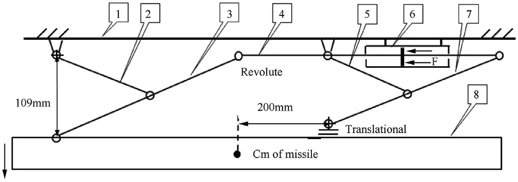
Fig.1. The configuration of the AMELT launcher in its initial stage: 1. Structure of the ejection mechanism, 2. Front support arm, 3. Front push arm, 4. Horizontal hydraulic piston rod, 5. Rear support arm, 6. Hydraulic actuated cylinder, 7. Rear push arm, 8.Missile.
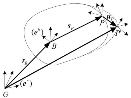
Fig. 2. Kinematic relations in the flexible body coordinate system.
The multi-flexible dynamics is described by using the coordinate system as shown in Fig. 2, which consists of the inertial coordinate system(er)and the floating coordinate system(eb).The former does not change with time,and the latter is to describe the movement and deformation of the flexible body,which is changed with the deformation of the flexible body.
In the coordinate system er, the motion of any pointPon the flexible body can be decomposed into a rigid translation and a rigid rotation relative to the system origin, or a deformation motion relative to the floating coordinate system.The positional motion ofPrelative toGcan be expressed as:

where r for the vector of pointPin the inertial coordinate system;rBis the vector of the origin of the floating coordinate system in the inertial coordinate system; A for the transformation matrix; spis the vector of pointPin floating coordinate system when the flexible body is not deformed; upfor the deformation vector of pointP,calculated by the modal coordinates:

where φPfor the assumed deformation modal matrix at pointPthat satisfies the ritz basis vector requirement, q is the generalized coordinate of deformation.
1) Kinetic energy T
The position,direction and mode of any nodePbefore and after deformation in the generalized coordinates of the flexible body are defined as:

The kinetic energyTof the flexible body is:

The mass matrix M(ξ)is the 3×3 dimension matrix,which can be expressed as:

wheret,r,andmare the translational,rotational and modal degrees of freedom,respectively.
2) Potential energy W
Potential energyWincludes two parts:gravity potential energy and elastic potential energy, which can be expressed by Eq. (8):

where K is the stiffness matrix of structural components, corresponding to the modal coordinates of q.
3) Dynamic equation of Multi-flexible bodies
Lagrange equation for flexible bodies is described by:

among them: Ψ is constraint equation; Q is generalized force projected in defined generalized coordinates ξ; λ is Lagrange multiplier corresponding to the constraint equation;Lis the Lagrange term, defined asL=T-W. Then the final differential equation is:

3. Dynamics simulation analysis of ejection process of a fixed topological launch mechanism
The simulation and analysis are performed on missile speed,the missile angular velocity and the vertical thrust, under the conditions of multi-rigid ejection mechanism and the multi-flexible ejection mechanism. As the missile ejection device is a highprecision mechanism, the assembly clearance of each joint is not considered in this study.
3.1. Main simulation parameters
Table 1 shows the main simulation input parameters of the airborne missile ejection dynamics model. The front support arm,the front push arm,the rear support arm and the rear push arm are made of aluminum alloy, with an elastic modulus ofE=70×109and the Poisson's ratio is 0.3.The missile is treated as a rigid body.The material of the piston rod is high-strength alloy steel, with an elastic modulus ofE=210×109, and the Poisson's ratio is 0.3.
3.2. Simulation results
The dynamic simulation analysis of the ejection process is carried out, under the assumption of the multi-rigidity ejection mechanism and the flexible state of the mechanism,respectively.In the flexible simulation model,the front support arm,the front push arm, the rear support arm, the rear push arm, and the horizontal piston rod are flexibly processed in finite element software.
Fig. 3 shows the ejection power generated by the horizontal hydraulic cylinder. The first 10 ms is the ejection power establishment phase, with a peak value of 58367 N at 10 ms. After that, the ejection power gradually decreases. The missile and the launcher are separated at 110 ms, with a power value of 26788 N.
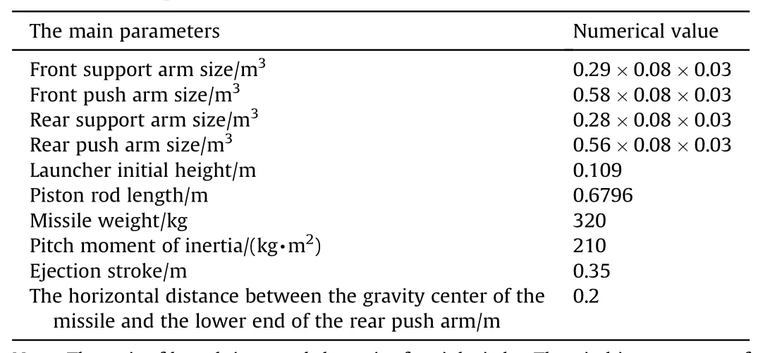
Table 1 Main simulation parameters.
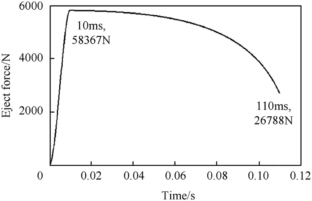
Fig. 3. Horizontal hydraulic ejection force.
Fig. 4 shows the separation speeds during the missile ejection process. It indicates that, under multi-rigid body conditions (black line in Fig. 4), the speed between the missile and the launching device is 7.7 m/s at the time of separation;the blue dotted line is the simulation result of the flexible mechanism, with a separation speed of 7.85 m/s. As the difference between the two results is small, the flexibility of the mechanism has little effect on the separation speed.
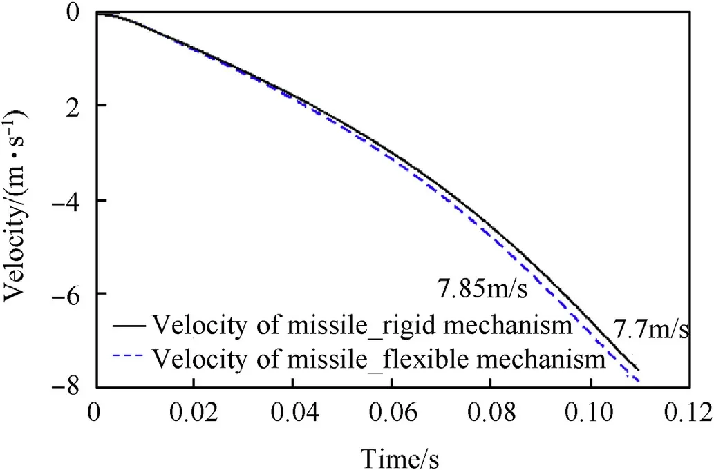
Fig. 4. Separation speed simulation during missile ejection.
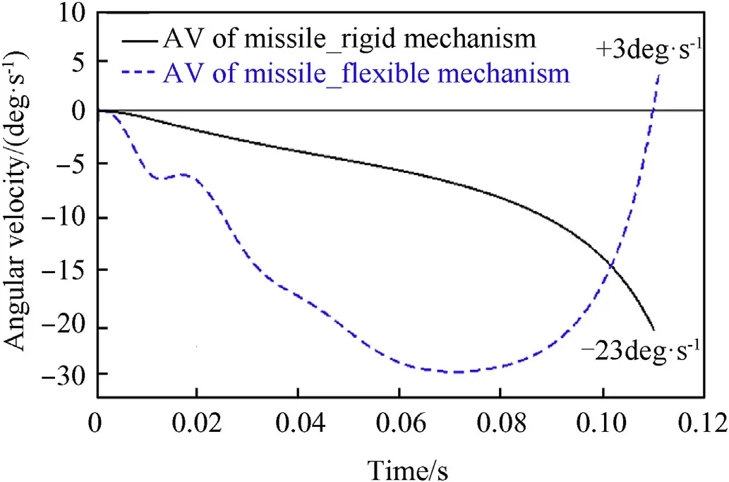
Fig. 5. Angular velocity of the missile during ejection process.
Fig. 5 shows the angular velocity of the missile during ejection process.Among them,the simulation result of the multi-rigid body demonstrates that the angular velocity at separation time is -23 deg/s,while the value is+3 deg/s at the time of ejection separation for the flexible mechanism.It can be seen that the flexibility of the mechanism has a great influence on the separation angular velocity. For the air-to-air missile, the ejection angular velocity range is about -20 ± 10 deg/s.
For air-to-air missile ejection separation of angular velocity, to ensure that a missile can rapidly away from the aircraft after separation, missiles should have certain downward angular velocity.Normally, this downward angular velocity generally should be greater than -15 deg/s. Therefore, it seems that a downward angular velocity of-23 deg/s could well meet the requirements of the multi-rigid design. However, Fig. 5 shows that the angular velocity of the flexible mechanism is+3 deg/s,which does not fit the range of -20 ± 10 deg/s. It is already in the “head-up” angular velocity state and may fly towards the carrier, giving a serious threat to launch safety.
The analysis of the vertical force on the missile induced by the push arms can better explain the reason of “head up” problem of the missile during ejection process.Fig.6 is the downward force on the missile induced by the front and rear push arms,under multirigid and multi-flexible simulation conditions, respectively.
As shown in Fig. 6, the force from the front push arm is in a continuously increasing state,and its value is 14057 N at the time of ejection separation; while the rear push arm force is in a continuous increase state in the early stage but sharply reduced in the later period, with a force of 14631 N at the time of ejection separation.
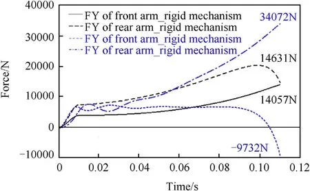
Fig. 6. The downward force on the missile by the front and rear push arms under the multi-rigid and multi-flexible body conditions.
Simulation results demonstrate that after enabling the mechanism flexibility,the vertical force results of the front and rear push arms on the missile shows significant difference with that of the multi-rigid dynamics model, especially at the end of the ejection,where the force of the front push arm is decrease rapidly instead of continuously increasing. The force is -9732 N at the time of separation; In contrast, for the rear push arm, its value continues increasing instead of decreasing at the end,reached 34072 N at the time of ejection separation.
Therefore,the huge force changes of the missile by the front and rear push arms could result in seriously deviating from the ideal design value of the angular velocity of the missile at the moment of ejection separation, even the occurrence of “head-up”, which seriously threatens the safety of missile launch. Consequently, to resolve this problem, it is necessary to reduce the influence of thrust force change caused by the front push arm and the rear push arm.Specifically,in the last stage of the ejection process, the force acted by the front push arm should be increased,while the force of the rear push arm needs to be decreased.
4. Dynamics simulation analysis of ejection process using variable topological design
4.1. Variable topological design of ejection mechanism
To prevent the angular velocity of the airborne missile from deviating from the designed value, it is necessary to suppress the flexibility effect of the entire ejection mechanism.Considering that the ejection time is only 0.11 s and the ejection force reaches up to several tons, the existing flexible suppression methods of various mechanisms have great limitations.
Fig.7 is the variable topology design of ejection mechanism.At the hinge of the shaft hole of the front main arm and the horizontal piston rod, a clearance having a specific direction and size is designed in the rotary hole, which is different from the random machining error generated during manufacturing. The clearance designed in this research is a horizontal U-shaped gap located behind the rotating shaft. In the initial state, the rotating shaft is located at the front of the U-shaped gap.
In the initial stage of ejection,due to the existence of horizontal U-shaped gap,the piston rod cannot apply force on the front push arm. The ejection power of the piston rod can only act on the missile via the rear push arm. During the ejection process, the rotating shaft in U-shaped gap slips backward, reaching the rear end of the U-shaped gap after the mechanism stretching a certain distance. The horizontal piston rod then can generate horizontal force on the rotating shaft, further pushing the front push arm which acts on the missile in vertical downward direction. The mechanism continues to operate until the missile is separated from aircraft.
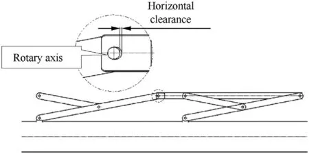
Fig. 7. Variable topology design of ejection mechanism.
During the ejection process, the mechanism performs a topological transformation when the rotating shaft reaches the rear end of the U-shaped gap. The front pushing arm is changed from the rotating and the sliding to the relative rotation with respect to the piston rod, that is, the movement of the Prismatic-Revolute (PR)pair is changed to a Revolute(R)pair.Therefore,the U-shaped gap topology design here is referred to as the Prismatic-Revolute-Revolute (PR-R) kinematic pair. After the topology of the mechanism is changed, the ejection power is provided by both the front and rear push arms instead of only rear arm.
4.2. Dynamic contact force model of the PR-R kinematic pair
In the case of the variable topology design, the rotation pair adopted in the fixed topology mechanism is not fit as the motion constraint of the front push arm,the horizontal piston rod and the rotating shaft.Instead,the contact force between the rotating shaft and the horizontal piston rod is used to judge whether the rotating shaft and the horizontal piston rod have the interaction force.While considering the practical design of the structure, the front push arm and the rotating shaft continue to adopt the rotation constraint.
The model of normal contact forceFof PR-R motion constraint considers both the material stiffness at the contact location and the damping effect in impact event.In this case,the classical Lankarani-Nikravesh dynamics model [18] is used:

Among them:Kfor the contact stiffness of the rotating shaft and the horizontal piston rod at the gap,5×107 N/mm is taken in this paper.Cfor the damping coefficient of the contact,δ for embedding depth,nfor the index coefficient, take 2.2 in this paper. The relationship between multiple groups of embedded depth δ and contact forceFcan be calculated according to the structural design parameters at the hinge of the launching mechanism by using the finite element method, and thenKandnin Eq. (11) can be determined by combining results of the least square method and engineering experience.

whereeis the material recovery coefficient of the horizontal plug rod structure, take 0.8 in this paper; Pc5-Antarctica_JASTP_keywords_V2 is the initial relative velocity when the rotating shaft is in contact with the horizontal piston rod.
4.3. Simulation results and analysis
The simulation was conducted on the forces of the front and rear push arm, and the ejection separation angular velocity of the variable topological ejection mechanism after using the PR-R gap pair.The PR-R gap in the simulation model is set to 2 mm.
Fig.8 is a normal contact force at the PR-R gap pair.It shows that the rotation axis of the PR-R gap pair begins to contact with the piston rod at 6.7 ms, and the contact force is 18700 N. At this moment,the topological form of the ejection mechanism changes.Before that, the piston rod has no force applied on the front push arm. While after that, the piston rod has a force on the front push arm, and the force gradually increases, reaching a peak of 24542 N at 55 ms, and then the contact force gradually decreases and approaches zero at 110 ms.
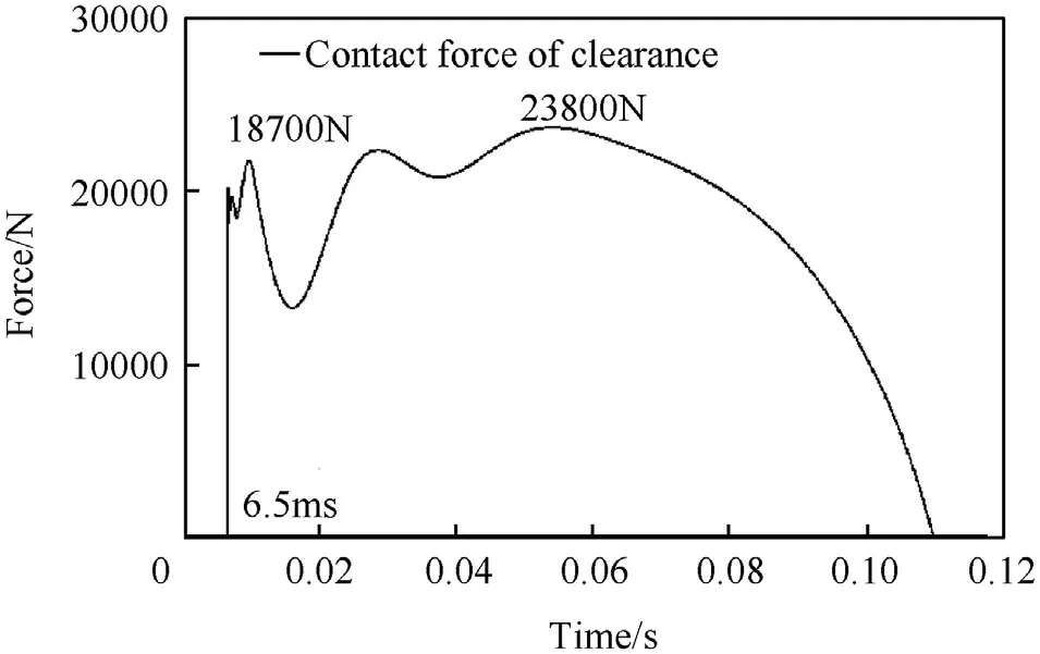
Fig. 8. Contact force at the PR-R gap.
Fig. 9 shows the missile displacement during ejection process.At 6.7 ms, the missile is in the initial position of the ejection compared with the entire ejection stroke of 350 mm, with only 0.4 mm downward displacement. Therefore, the topology switching of the variable topology mechanism completes in the initial startup phase.
The purpose of the clearance design is to change the acting force on the missile by the front and rear push arm at the last stage of the ejection process, further to avoid the “head up” problem of the missile. Fig. 10 shows the influence of clearance design on the vertical force acted by the front and rear push arms on the missile during the ejection process.
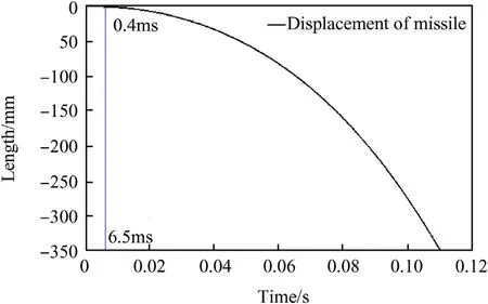
Fig. 9. Missile displacement during ejection process.
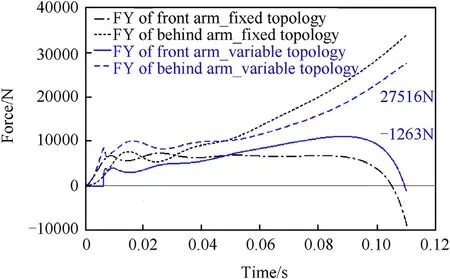
Fig.10. Effect of clearance design on ejection force of the front and the rear push arm.
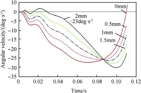
Fig.11. Separation angular velocity simulations for different gap sizes.
Before 6.7 ms,the vertical force of the variable topology ejection mechanism to the missile is 0; after about 50 ms, the variable topology design is adopted, and the force by the front push arm is higher than that of the fixed topological mechanism,while the rear push arm has a smaller force on the missile than that of the fixed topology mechanism. Therefore,the variable topology mechanism can generate a larger pitch down torque on missile in the late stage of the ejection, preventing the missile from “heading up” event.
Fig.11 shows the separation angular velocities of missile with different sizes of PR-R gap pairs. It is simulated under the gaps of 0 mm, 0.5 mm,1 mm,1.5 mm, and 2 mm, respectively.
Results show that the larger the gap, the higher the angular velocities.With the gap size of 2 mm,the missile achieves the same separation angular velocity of -23 deg/s as in the condition of multiple rigid bodies at the time of separation. It can be seen that the PR-R gap pair can greatly adjust the ejection separation angular velocity of the airborne missile ejection mechanism to ensure the safety of the launch.
5. Discussion
In order to facilitate readers to reproduce the simulation process and results,the mechanism in this paper is a simplified mechanism of the original mechanism,and the members of the mechanism are given in simple shape, namely rectangular members with holes,without considering the mutual structural interference of the members during the assembly of the mechanism and during the movement process. The fabrication and subsequent verification of the experimental mechanism require cutting and grooving of the interferential parts of the mechanism during assembly and movement. However, the shape of such mechanism components is relatively complex,which is not suitable for readers to simulate and reproduce. Therefore, there is no experimental data of physical prototype which is completely consistent with the virtual prototype state in this paper.However,this design has been verified by a real object prototype and has a good effect of inhibiting the flexible effect of the mechanism. After optimization design, the ejection separation parameters consistent with the rigid hypothesis can be achieved.
Readers can manufacture a physical prototype for experimental verification based on the design parameters provided in the paper,and the design parameters of the reader's physical prototype does not need to be completely consistent with those in the paper. The relevant design data of ejection mechanism given in this study is sufficient for readers to simulate and reproduce the results.
6. Conclusion
Due to the flexibility of the various components of the airborne missile ejection mechanism, the missile ejection separation parameters seriously deviate from the ideal design value of the multirigid body,which threatens the launch safety.The variable topology flexible mechanism design strategy proposed in this paper aims to solve this problem. The main conclusions are:
1) The flexibility of the ejection mechanism has little effect on the separation speed of the missile, but it can greatly influence the separation angular velocity and threaten the launch safety;
2) Adopting the variable topology design via clearance design that can effectively adjust the ejection force on the missile produced by the front and rear push arms, thereby realizing a great adjustment of the separation angular velocity of the missile.
3) Different ejection separation angular velocities can be obtained via different gap sizes.A separation angular velocity of-23 deg/s can be achieved when the gap size is 2 mm.
4) The dynamic design of the variable topology multi-flexible mechanism is to optimize the dynamic performance of the mechanism from the overall perspective of the flexible mechanism, and is not limited to each individual component of the mechanism.This design is easy to be implemented and effective in engineering,and can be applied to similar high-speed flexible mechanisms.
Acknowledgement
I would like to thank one of my funding support, which is Aerospace Science Foundation (NO. 2017ZC12008).
杂志排行
Defence Technology的其它文章
- A comparison of the ballistic behaviour of conventionally sintered and additively manufactured alumina
- Effect of operating temperature on aged single lap bonded joints
- Investigation on energy output structure of explosives near-ground explosion
- Characteristics structure analysis on debris cloud in the hypervelocity impact of disk projectile on thin plate
- A fast-running method for blast load prediction shielding by a protective barrier
- Coating processes towards selective laser sintering of energetic material composites
