Multi-Peptide Adsorption on Uncharged Solid Surfaces:A Coarse-Grained Simulation Study
2020-05-22RuosangQiuJieXiaoXiaoDongChen
Ruosang Qiu, Jie Xiao*, Xiao Dong Chen*
a China-Australia Joint Research Center in Future Dairy Manufacturing, School of Chemical and Environmental Engineering, College of Chemistry, Chemical Engineering and Materials Science, Soochow University, Suzhou 215123, China
b Department of Chemical Engineering, Monash University, Clayton, VIC 3800, Australia
Keywords:
A B S T R A C T On-aim control of protein adsorption onto a solid surface remains challenging due to the complex interactions involved in this process.Through computational simulation,it is possible to gain molecular-level mechanistic insight into the movement of proteins at the water-solid interface,which allows better prediction of protein behaviors in adsorption and fouling systems. In this work,a mesoscale coarse-grained simulation method was used to investigate the aggregation and adsorption processes of multiple 12-alanine (12-Ala) hydrophobic peptides onto a gold surface. It was observed that around half (46.6%) of the 12-Ala peptide chains could form aggregates.30.0%of the individual peptides were rapidly adsorbed onto the solid surface; after a crawling process on the surface, some of these (51.0%) merged into each other or merged with floating peptides to form adsorbed aggregates.The change in the solid-liquid interface due to peptide deposition has a potential influence on the further adsorption of single peptide chains and aggregates in the bulk water. Overall, the findings from this work help to reveal the mechanism of multi-peptide adsorption, and consequentially build a basis for the understanding of multi-protein adsorption onto a solid surface.
1. Introduction
Protein adsorption is a common phenomenon that plays either negative or positive roles in different areas of application. In wastewater treatment and food engineering, protein adsorption onto the internal surfaces of equipment and piping can result in biological fouling[1-4],which can lead to an increase in the operational and cleaning costs of the facility, while reducing its operational efficiency and end-product quality. Protein fouling reduction in core manufacturing facilities has thus received a considerable amount of research interest and financial investment.In other processes,however,protein adsorption is preferred.Improved protein adsorption can help to dewater sludge by breaking up the watersludge matrix in the wastewater treatment process[5-7],promote nanomaterial-based targeted drug delivery with a lower biological rejection rate [8-10], and increase the recovery efficiency in protein purification [11,12]. Thus, a better understanding of protein adsorption mechanisms is particularly helpful for the control of protein adsorption rates for specific end-use requirements[1,2,4,13,14].
Protein adsorption mechanisms have been explored through experimental studies. Special attaching fragments of proteins[15,16]and the overall adhesion process[11,17]have been identified by studying the changes in the surface characteristics of the solid surface over the course of the adsorption process. However,any slight adjustment made to the surrounding environment—especially the pH and ionic strength of the bulk solution—may lead to significant changes in the intermolecular interactions of protein molecules [1,11,17-20]. Such changes in adsorption dynamics are generally difficult to predict due to a lack of understanding of the adsorption mechanisms involved. Moreover, it is extremely difficult to extend the findings of existing studies to new biomaterials.When introducing a change into an adsorption system, all experiments must be carefully repeated once again, because in-process dynamic fouling data is difficult to obtain at present [11,12]. The limitations of experimental studies significantly slow down the exploration rate and dramatically increase the associated research costs in this field. Thus, a cheap but reliable method for the study of in-process protein adsorption dynamics is required.
Numerical simulation is a promising alternative for the study of adsorption mechanisms for different biomaterials. This technique can track moving trajectories of all protein components under different conditions for further analysis[21-27].Protein regions that facilitate adhesion onto a solid surface can easily be identified using this method[21,27-29],and the driving forces that push proteins in bulk water to move toward a solid surface can be quantitatively compared [23,30]. However, the most popular of these methods,all-atom molecular dynamics(MD)simulation,is computationally limited by the size of the system.Only one rigid protein structure can typically be studied at a time when utilizing this numerical method without compromising the time complexity of the adsorption process [21,27-29]. Yet in reality, many protein molecules in the solution can interact with each other and, when adsorbed onto a solid surface, the deposit can demonstrate either a denatured or an aggregated structure [19,31-34].
To investigate a relatively large system that involves multiple proteins while overcoming the computational limitation of allatom MD simulations, coarse-grained force field is a widely used method that reduces the number of particles in a simulation box[25,35-44]. Among different kinds of coarse-grained force fields,Martini is very popular,and is designed for large biomolecular systems[25,41-44].This force field has been widely used in the study of peptide aggregation [45], pore formation in a lipid bilayer [46],adsorption of organic molecules on metal nanoparticles[47],crystalline cellulose microfibers[48],and more.However,it is based on MD simulation and is therefore limited by the timescale that an MD simulation can cover [49,50]. When dealing with larger time and length scales, Monte Carlo (MC) simulation has an advantage[40,51]. Pandey and colleagues [35,36,40,52-55] have contributed greatly to the simulation of multiple peptides with a unique allresidue MC model.This lattice Monte Carlo(LMC)model can effectively characterize adsorption density[40,53,56-58],polymer folding [36,39,54,55,59], binding energy [40,52,53,60], and supramolecular assembly [35,58,61] of multiple peptides. Yet the all-residue model deletes all steric structures of amino acid residues, which are important when multiple small-volume peptides are involved. When extending the application of this model, however, its use is limited by its unique interaction parameters [40].Thus, a combination of the Martini force field and LMC model can provide the advantages of both in maintaining model accuracy while accelerating the simulation speed.
With this motivation, a new model was developed by integrating the LMC model and the Martini coarse-grained force field[51].The new model was successfully applied to investigate the single peptide adsorption process, and has shown potential in dealing with multi-chain systems with sufficient side-chain details.Hence,this hybrid model was used in the present work to study the adsorption process of multiple peptide chains. As a preliminary but critical step toward an eventual study of multi-protein adsorption,simplified systems were built.Each system consisted of a few 12-alanine(12-Ala)hydrophobic peptide chains solvated by water beads and a highly stable gold surface, onto which the peptides could adsorb. Based on the moving trajectories of individual peptide chains and peptide aggregates,the peptide adsorption mechanisms were analyzed further.
2. Modeling methodology
In this study, a hybrid coarse-grained LMC model developed in our previous study was extended to investigate the adsorption of multiple peptides on a gold Au(111)surface.Details of the method can be found in Ref. [51]. Periodic boundary conditions were applied to the x and y directions of the simulation box(7.5 nm×7.5 nm×7.5 nm). In the z direction, unmovable gold and water beads respectively filled the bottom part and the top 1.20 nm deep space to provide a solid surface and a stable bulk liquid phase. All coarse-grained beads used in this simulation were based on the four-to-one Martini mapping scheme [42,43]. Polar,charged,and uncharged beads with specific charge sites were used to represent groups of atoms in the peptide chains[42,43].Each set of four water molecules was modeled as a polarized neutral coarsegrained bead with two opposite charges [41], and each gold atom was represented by a gold bead [62]. The surface of gold has been widely used in studies attempting to reveal protein/peptide adsorption mechanisms, due to its stability and well-accepted interaction potentials[23,30,40,63].The peptide chain in this study was a linear 12-Ala (A-A-A-A-A-A-A-A-A-A-A-A) chain, since Ala is frequently observed in vertebrates [64]. According to the mapping scheme, the Ala residue was coarse-grained into only one P4 type bead without side chains, which was the same type as the water beads. Twelve single beads were linked together to form a linear peptide.This simple linear structure facilitates effective simulation of the aggregation and adsorption processes of multiple peptide chains.
To calculate the interaction potentials between beads, the cutoff radius rcut-offwas set at 1.2 nm. Non-bonded interaction was quantified using the Lennard-Johns potential, which was shifted from 0.9 to 1.2 nm, and the electrostatic potential, which was shifted from 0 to 1.2 nm [23]. The parameters were taken from the Martini force field and were extended through the Lorentz-Berthelot mixing rule [24,25,41-43]. The bonded interaction was replaced by the rules adopted from the bond-fluctuation model[37,65,66]. The acceptance of a movement was determined by the Metropolis algorithm after comparing the total energy before and after a movement [37,40,65].
To construct the initial configuration of the system,a solid surface layer (thicker than rcut-off) was placed in the bottom part of the simulation box[51].This layer was set as rigid throughout the simulation.Next,a specific number of peptide chains were inserted at locations over 2 nm away from the surface with random configurations,so that these peptide chains could interact with neither the solid gold surface nor the two aggregated water layers that formed adjacent to the solid surface.Here, the strong interaction between the uncharged surface and the neutral water beads was the main cause of the formation of the two aggregated water layers, which were located respectively 0.375 and 0.875 nm away from the gold surface [51]. The peptide chains were then solvated using water beads,whose number was adjusted to ensure that the relative density at locations further than 2 nm away from the gold surface was maintained at 1 under the environmental conditions of 298 K and 1.01×10⁵Pa. In the initial equilibrium stage, the peptide chains were set as rigid until the difference in the total system energy within adjacent 25 MC steps was less than 500 kJ·mol-1,after which the peptide chains were released for morphological evolution.
During the simulation, some peptide chains gradually moved closer to each other and formed aggregates.The minimum distance between two peptide chains was defined as the distance between the two closest beads of the respective chains.When three peptide chains were located within 0.5rcut-off=6 Å of each other, they formed an aggregate (Fig. 1). Following this criterion, when a new chain moved to a position that was less than 6 Å away from two peptide chains in an aggregate,it could then be regarded as being integrated into the aggregate.Because of the long linear structure,it is possible for a peptide to be shared by an aggregate in bulk water and an adsorbed aggregate at the same time,according to the criterion.Thus,a further requirement was set in order to clarify that only an adsorbed peptide belongs to an adsorbed aggregate; otherwise,the peptide belongs to the aggregate in bulk water.

Fig. 1. Illustration of a peptide aggregate (grey) and an individual peptide chain(red). The three grey chains ①, ②, and ③are less than 6 Å away from each other and thus belong to one aggregate. The red chain ④does not belong to the grey aggregate since it is within 6 Å of peptide ③only.
Three types of information were extracted from the movement trajectories of all beads for adsorption process analyses:
(1) The vertical distance of a chain from the surface. This is quantified by the average of the z coordinate values of all beads in that chain.
(2) The radius of gyration. The radius of gyration (Rgyr) is defined as the average distance of all beads from their centroid in an aggregate, and thus shows the degree of aggregation of a group of coarse-grained beads. A higher Rgyrvalue
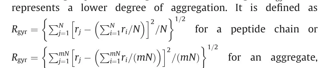
where riis the distance between bead i and the center of peptide chain or aggregate, and rjis the distance between bead j and the center of peptide chain or aggregate, N is the number of beads in one peptide chain(equals to 12 for a coarse-grained 12-Ala peptide chain) and m is the number of chains in one aggregate [67].
(3)The partitioned force in the z direction exerted on each bead by all neighboring beads[51].The summarized partitioned force in the z direction of all beads is the total force—consisting of the Lennard-Jones interaction and the electrostatic interaction—that the water, surface, and amino acid beads of other peptide chains exert on a certain peptide chain or an aggregate. A negative value indicates an attractive force pointing toward the surface,whereas a positive value indicates a repulsive force pointing away from the surface.
3. Results and discussion
3.1. Adsorption and aggregation processes characterization and analysis
The adsorption and aggregation processes of 16 peptide chains were investigated in order to analyze peptide movement trajectories (Fig. 2). Chain 10 was the first to adsorb onto the gold surface(Fig. 2(b)), followed by Chains 2, 16, and 4 in separate events(Figs. 2(c-e)). Peptides left in the bulk solution gradually formed two groups after the 75 000th MC step; these groups consisted of①Chains 1,3,7,9,12,13,and 15(labeled by filled circled numbers in Fig. 2); and ②Chains 5, 6, 8, and 14 (labeled by hollow circled numbers in Fig. 2). Group 1 formed a large aggregate at the 270 000th MC step, while Group 2 formed an aggregate at the 113 000th MC step, and then developed a relatively looser structure due to vibration.

Fig.2. Representative screenshots of the simulated adsorption process: (a) 0th; (b) 75 000th; (c) 113 000th;(d) 175 000th; (e) 215 000th; and (f)270 000th MC steps. The numbered lines represent 12-Ala peptide chains.The ordered yellow beads at the bottom of the simulation domain are Au beads;the dark blue beads indicate the interaction cut-off range from surface beads,while the light blue beads represent water beads that can interact with surface beads.Any water beads beyond 1.2 nm above the surface are not shown in this figure. Each specific MC step contains three subplots; the top right, bottom left, and bottom right panels show the top (red), left (green), and front (blue)views of the simulation box, respectively.
Thus,three kinds of peptide chain situations were identified by evaluating their final positions and configurations at the 270 000th MC step (Fig. 2(f)):
(1) A multi-peptide aggregate. One aggregate was formed by seven chains—namely, Chains 1, 3, 7, 9, 12, 13, and 15 (labeled by filled circled numbers in Fig. 2).
(2)Adsorbed single peptide chains.Chains 2,4,10,and 16 were adsorbed as single peptide chains.
(3)Single peptide chains in the bulk solution.Chains 5,6,8,11,and 14 remained as single peptide chains in the bulk solution.
The simulation of 16-peptide chains’ case was repeated 20 times for 270 000 MC steps; the pooled distribution of the fate of single peptide chains after each simulation is summarized as follows:
· Multi-peptide aggregates in the bulk water: 31.3%
· Single peptide chains in the bulk water: 33.4%
· Adsorbed multi-peptide aggregates: 15.3%
· Adsorbed single peptide chains: 20.0%
In the following sections,the aggregate,the adsorbed Chain 10,and the stand-alone Chain 11 in the bulk solution of the simulation results exhibited in Fig. 2 are selected for further analysis.
3.1.1. Adsorption of a single peptide chain
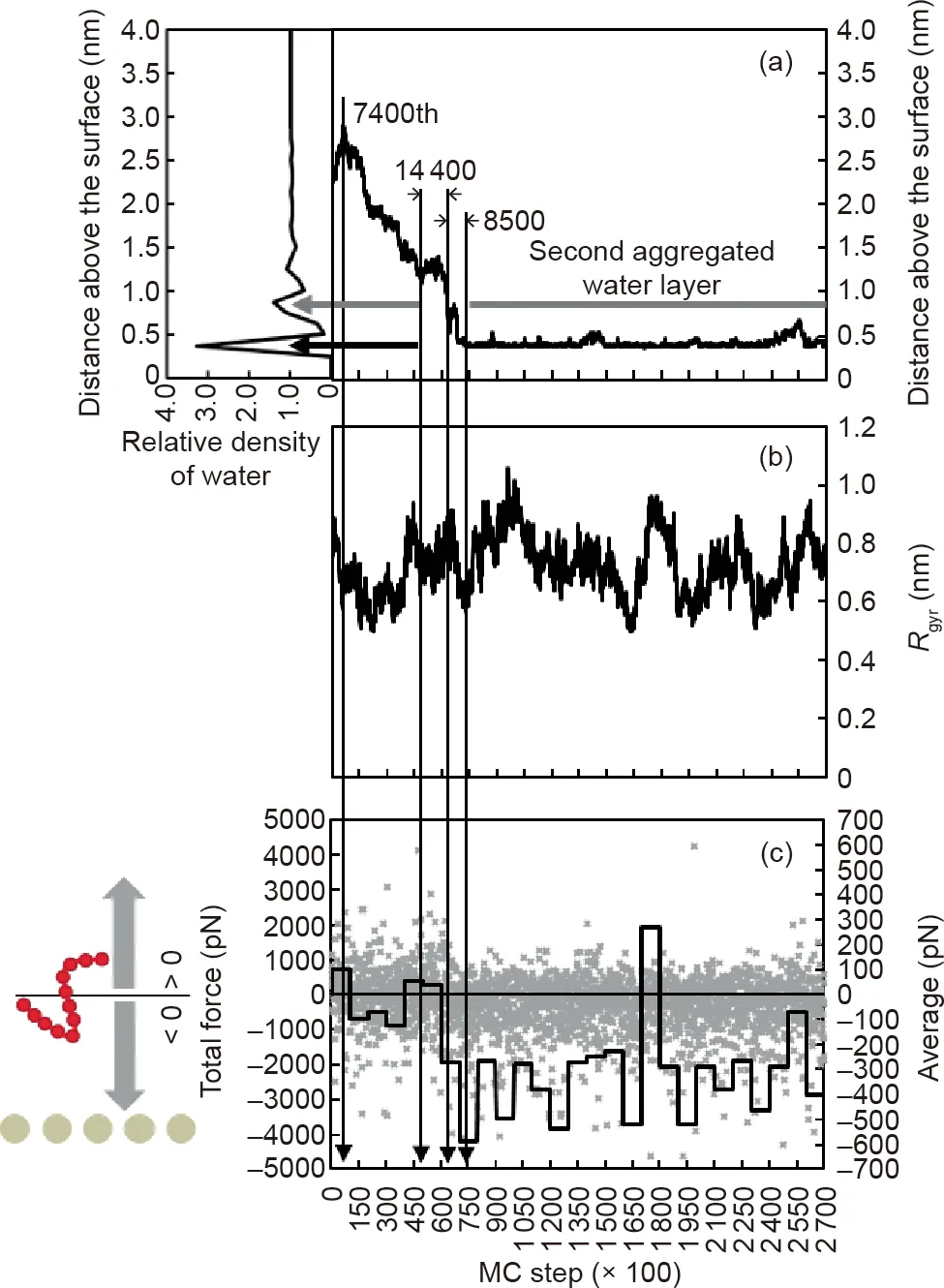
Fig.3. Chain 10’s trajectory in terms of(a)the distance above the surface and(b)its radius of gyration,together with(c)the total force experienced by the chain during the adsorption process. In (a),black and grey horizontal arrows show the locations of the first and the second aggregated water layers, respectively. In (c), grey points show the in-process data of the total force and the black line represents the average value for every 10 000 MC steps.A negative value indicates a force pointing toward the surface,while a positive value indicates a force pointing away from the surface.
At first, Chain 10 was in close proximity to Chain 5 (Fig. 2(a)).From analysis (Fig. 3), Chain 10 moved away from the surface for 7400 MC steps, and then headed toward the surface (Fig. 3(a)).Although Chain 10 was hindered by the physical barrier of the second aggregated water layer (0.875 nm away from the surface) for 14 400 MC steps and the first aggregated water layer (0.375 nm away from the surface) for 8500 MC steps, it eventually adsorbed onto the gold surface. When it reached the second aggregated water layer, only a slightly larger proportion of the negative value of the total force showed the downward attraction(Fig.3(c)).After it adsorbed onto the gold surface at the 75 000th MC step, the negative force became dominant. During the adsorption, no clear trend of Rgyrevolution could be observed, as only a small number of coarse-grained beads were involved in a single peptide chain(Fig. 3(b)).
3.1.2. Stand-alone peptide in bulk solution
At the end of the simulation,Chain 11 was the only single peptide chain still vibrating in the bulk solution (Fig. 2(f)). Chain 11 was originally located at the edge of a space crowed with peptides(Fig. 2(a)). As time proceeded, it gradually migrated upwards to form an aggregate with Chains 1 and 13 (Figs. 2(b,c)). Subsequently,however,as Chain 3 approached the aggregate with a better posture and position, Chain 11 was replaced and eventually dissociated from the aggregate to vibrate alone (Fig. 2(e)).

Fig.4. Chain 11’s trajectory in terms of(a)the distance above the surface and(b)its radius of gyration,together with(c)the total force experienced by the chain.In(c),grey points show the in-process data of the total force and the black line represents the average value for every 10 000 MC steps, where a negative value indicates a force pointing toward the surface, while a positive value indicates a force pointing away from the surface.
Through numerical analyses (Fig. 4), it was observed that over the course of simulation, Chain 11 made two attempts to break through the aggregated water layers at the 62 000th and 243 800th MC steps (Fig. 4(a)). During the first failed attempt at the 62 000th MC step, Chain 11 was in close proximity to Chains 1 and 13. It could directly interact with the aggregated water layers, but was located outside the interaction range of the solid surface beads (Figs. 2(b) and 4(a)). Before the next attempt, Chain 11 reached the highest recorded z position at around the 160 000th MC step(Fig.4(a)).At this simulation point,the average distance of the peptide from the gold surface was about 3 nm, placing it outside the interaction range of the two aggregated water layers; in addition, the total force on Chain 11 changed from repulsive to attractive toward the surface later on (Fig. 4(c)).
It was notable that the top solvent layer in the simulation box was more than 3 nm away from Chain 11. Hence, the change in momentum direction of this peptide chain at the 160 000th MC step was not due to the restriction of the simulation box size,but was rather due to a dominant downward attractive force,possibly exerted by other peptide chains in the vicinity beneath it.The second attempt started at the 243 800th MC step and lasted for less than 60 000 MC steps(Fig.4(a)).This time frame was too short for the peptide chain to obtain an effective configuration that could break through the hindrance of the physical barrier of the two aggregated water layers to adsorb onto the surface.
As the size of a single 12-Ala peptide chain is relatively small,no specific trend of Rgyrcould be observed in Figs. 3(b) or 4(b). However, these results can be compared with the Rgyrdynamics of the aggregates, as outlined in the next section.
3.1.3. Aggregation of multiple peptides
In this study, when any part of a peptide chain was located within 0.5rcut-offof two other chains, these three peptide chains were regarded as a multi-peptide aggregate (Fig. 1). As shown in Fig. 2(f),at the end of the simulation(i.e., the 270 000th MC step),only one aggregate with seven peptide chains was formed. In this section, the dynamics of this aggregate are investigated in detail.
The screen shots shown in Fig.2 clearly illustrate the formation of this aggregate. At the beginning, all chains were located about 2.2 nm away from the surface(Figs.2(a)and 5(a)).The initial positions of Chains 1,2,7,8,9,11,12,13,and 16 were located close to each other, while Chains 3 and 15 were located a bit further away(Fig. 2(a)). A few steps later, Chains 1, 3, 8, 11, and 13 had assembled(Fig.2(b)).Subsequently,due to their loose structures,Chains 8 and 11 started to dissociate from the core,while Chains 1,3,and 13 formed an aggregate (Figs. 2(b,c)). Concurrently, Chains 9, 12,15, and 16 formed another stable aggregate, while Chains 2 and 7 were located in the vicinity (Fig. 2(c)). As time went by, the two smaller aggregates mentioned above, along with the single peptide Chain 7, integrated together into a large aggregate entity(Fig. 2(d)). During this integration process, Chains 2 and 16 left the aggregate and successfully adsorbed onto the solid surface(Figs. 2(c,d)). Although Chain 9 was located closed to Chains 2 and 16,these attractions were insufficient to facilitate the adsorption of the aggregate core in the bulk water onto the surface for the duration of the simulation (Figs. 2(e,f)).
The movement trajectory of this aggregate was further analyzed quantitatively.Before the 113 000th MC step,Rgyrdecreased slowly from 2.3 to 1.7 nm(Fig.5(b)).Two abrupt increases at the 48 900th and 50 000th MC steps were caused by the periodic boundary conditions when Chain 3 moved across the simulation boundary(Figs.2(a-c)).Between the 113 000th and 130 900th MC steps,a dramatic drop in Rgyrindicated the formation of the aggregate (Figs. 2(c-d)and 5(b)), after which the whole aggregate moved slightly away from the surface with a stable Rgyrof around 1.5 nm.Because there was a large number of peptide beads in this aggregate, this movement away from the surface is hardly observable in Fig. 5(a).However,this trend could be forecast by the higher overall repulsive force after the 225 000th MC step(Fig.5(c)).
Over the entire aggregate formation process, the z-coordinates of the member peptide chains were relatively stable except for Chains 3, 9, and 15. Chain 3 was the newest member of the aggregate. It was fully integrated into the aggregate after the 175 000th MC step (Figs. 2(d-e)), when a downward movement was observed(Fig.5(a))and the aggregate’s integrity level became stable(Fig.5(b)).Chain 15 was located at the edge of the aggregate and thus had a higher mobility than the other member peptide chains; nevertheless, its apparent movement was still restricted by that of the aggregate core. Concurrently, Chain 9 fluctuated at the bottom of the aggregate for a period of time (grey line in Fig. 5(a)) before being pulled away from the surface by its neighboring chains after three failed adsorption attempts.

Fig. 5. Evolution of (a) average distance above the surface, (b) radius of gyration,and (c) total force experienced by the aggregate. In (a), central positions for all members are shown.Black and grey horizontal arrows indicate the locations of the first and second aggregated water layers, respectively. In (b), the remarkable increases of Rgyr between the 45 000th and 60 000th MC steps were caused by periodic boundary conditions when Chain 3 moved across the boundary of the simulation box.In(c),the black line shows the average force value for every 10 000 MC steps. A negative value indicates a force pointing toward the surface, while a positive value indicates a force pointing away from the surface.The formation of the aggregate is illustrated on the right side of the figure.
In comparison to Chains 2 and 16,which successfully adsorbed onto the gold surface, the failed attempts of Chain 9 highlight the influence of the surrounding environment on the success of peptide adsorption. Initially, Chains 2, 9, and 16 were all located at the bottom of the aggregate (Fig. 2(b)). Chain 9 was attached to the surface, with one terminal in a relatively vertical posture(Fig.2(b)).This posture was not preferable for a successful adsorption,since the peptide’s center of mass was too high for it to move quickly toward the gold surface. In contrast, even though the anchoring attempt of Chain 2 was initiated later than that of Chain 9, Chain 2 quickly adsorbed onto the surface with both terminals due to its lower center of mass (Fig. 2(c)).
A comparison of the movement trajectories of single peptide chains and aggregates showed that the moving speed of a single peptide chain was much faster (Figs. 3(a), 4(a), and 5(a)). In addition, single peptide chains had more chances to break through the aggregated water layers and be adsorbed onto the surface(Figs. 3(a) and 4(a)). However, the diffusion of the large aggregate toward the surface was not clearly observed (Fig. 5(a)). Collectively, the simulation results imply that the first layer of foulants on a metal surface may well be composed of single peptide chains rather than aggregates. A similar phenomenon was observed experimentally by Jimenez et al. [17], who reported that the surface of steel was homogeneously covered with denatured βlactoglobulin rather than large aggregates after 1 min of adsorption. It is worth emphasizing that predicting the nature and chemical composition of the first layer of foulants is particularly critical for the development of any surface-modification-based anti-fouling strategies, because it is the first layer of deposit that changes the properties of the original solid-fluid interface.
This section compared the differences between single peptide chains and aggregates. Since the aggregated state is a common state of protein deposit, the mechanisms of aggregate formation,movement, and adsorption are further discussed in the next section.
3.2. The formation mechanism of aggregates
3.2.1. Movement of aggregates in bulk solution
As mentioned before, the aggregates that formed in the bulk solution moved slightly away from the surface after the Rgyrdropped to the lowest value (Figs. 5(a,b)). However, this phenomenon cannot be clearly identified from the movement trajectory of the aggregate. For a better understanding of the movement of aggregates, a four-chain system was simulated and analyzed (Figs. 6 and 7). The initial conditions of this case were the same as those of the 16-chain case, except that only four peptide chains were involved in the new system. As shown in Fig. 7,after the stand-alone peptide chain was integrated into the small aggregate formed by the other three chains at the 141 000th MC step,the Rgyrreached a stable minimum value(Fig.7(b)),indicating a maximal degree of clustering. With a relatively stable Rgyrof 1 nm, as shown in Fig. 7(b), an obvious movement away from the surface can be observed in Figs. 6 and 7(a). The evolution curve of the total force experienced by the aggregate confirms this movement trend (Fig. 7(c)). Before the 140 000th MC step, the average total force fluctuated around 0 pN, meaning that the forces pointing toward and away from the surface had more or less the same magnitude. Subsequently, an obviously larger proportion of the positive average total force could be identified from the 140 000th to the 240 000th MC step. At the end of the simulation,a higher proportion of the negative average total force stopped further movement of the aggregate away from the surface after the 280 000th MC step (Figs. 7(a,c)).

Fig. 6. Aggregation process of a four-chain system. Red lines represent 12-Ala peptide chains. The ordered yellow beads at the bottom of the simulation domain are gold beads;the dark blue beads indicate the longest interaction range from surface beads,while the light blue beads represent the water beads that can interact with the surface beads.All water beads beyond 1.2 nm above the surface are hidden in these figures.Each specific MC step has three subplots,with the top right,bottom left,and bottom right panels showing the top (red), left (green), and front (blue) views of the simulation box, respectively.
3.2.2. Formation of adsorbed aggregates
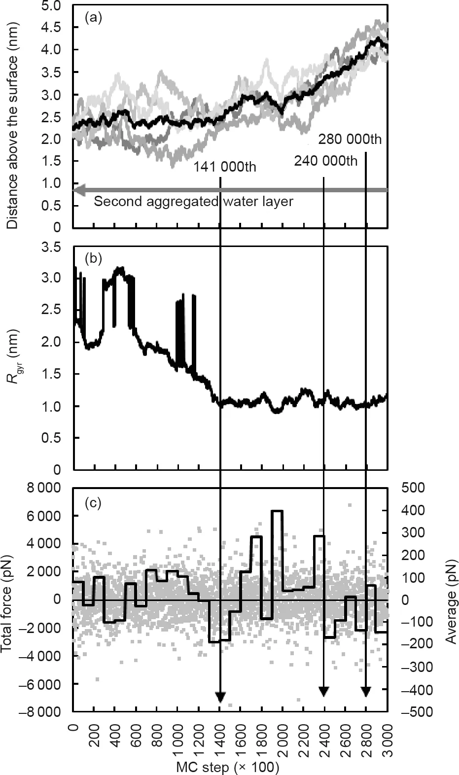
Fig. 7. Evolution of (a) distance above the surface, (b) its radius of gyration, and(c) total force experienced by the aggregate. In (a), central positions of all beads in the single peptide chains are shown by grey lines, while the central position of the aggregate is shown by a black line.In(b),the remarkable increases of Rgyr between the 45 000th and 60 000th MC steps were caused by periodic boundary conditions when peptide chains moved across the boundary of the simulation box. In (c), the black line shows the average force value for every 10 000 MC steps.A negative value indicates a force pointing toward the surface, while a positive value indicates a force pointing away from the surface.
It was found that adsorbed single peptide chains tended to crawl along the surface and meet with other adsorbed peptides to form an aggregate. The formation of an adsorbed aggregate was observed in an eight-chain system (Fig. 8). In the initial configuration,all chains were placed the same distance away from the surface as in previous cases (i.e., 2.2 nm). As shown in Fig. 8,three single peptide chains touched the surface at the 34 500th,44 300th, and 152 000th MC steps, respectively. Before the 220 000th MC step, all of them moved independently along the surface.This free-crawling stage slowed down once two of the single peptide chains confronted each other at the 220 000th MC step.The two chains finally stopped at a certain location when the third chain joined them. Meanwhile, the aggregate formed in the bulk solution, as highlighted by the green color in Fig. 8, and stayed a certain distance away from the surface.This phenomenon was also observed in the 16-chain and four-chain cases discussed above.
This crawling phase has been observed in other MD simulations as well [30], and helps to explain the experimental finding of the homogeneous coverage of denatured proteins at the first stage of protein adsorption[17].After single peptide chains with relatively high mobility are adsorbed onto the surface, they keep crawling until a stable adsorbed aggregate is formed. In comparison with the stable aggregates that form in the bulk water, the aggregates on the surface may have a higher homogeneity because they form under the influence of stronger interactions from the solid surface.The stable aggregates formed in the bulk water may tend to have a loose structure because a greater distance leads to weaker influence from the solid surface.
4. Conclusions
In this work,a mesoscale coarse-grained modeling method was developed to investigate the aggregation and adsorption processes of multiple peptides onto a solid surface that strongly interacts with water.Quantitative analyses of the adsorption dynamics provided in-depth understanding of the aggregation and adsorption mechanisms at the molecular level, which will be useful for the research and development of effective anti-fouling strategies in future. In summary, the following conclusions can be drawn(Fig. 9):
(1) The mobility of a single peptide chain is much higher than that of an aggregate. A single peptide chain tends to be hindered by the physical blockage of aggregated water layers adjacent to the solid surface when it attempts to attach onto the surface.However, it can overcome the barrier and be adsorbed on the solid surface.
(2)The aggregates formed by hydrophobic peptide chains in the bulk solution tend to move away from the surface after their clustering degree reaches a peak value.
(3)Adsorbed aggregates are most likely to be formed from individually adsorbed peptide chains. Adsorbed individual peptide chains form stable aggregates and change the interfacial characteristics of the solid surface, thus weakening the influence of the original surface on the further adsorption of other peptides and aggregates.
This mesoscale coarse-grained modeling method successfully reproduced the aggregation and adsorption process of multiple linear hydrophobic peptide chains on a gold surface.Future work will take into account sidechains, hydrophilicity of various functional groups, aqueous solution properties such as pH and ion strength,and other types of surfaces beyond the stable gold.
Acknowledgements
Fig. 8. Formation of an adsorbed aggregate. The lines represent 12 Ala peptide chains; red lines represent adsorbed peptide chains and grey lines represent stand-alone peptide chains.The green lines from the 185 000th to 290 000th MC step represent the aggregate in the bulk solution.The ordered beads at the bottom of the simulation box are gold beads; the blue beads represent the water beads that can interact with the surface beads. All water beads beyond 1.2 nm above the surface are hidden in these figures. Each specific MC step has three subplots, with the top right, bottom left, and bottom right panels showing the top (red), left (green), and front (blue) views of the simulation box, respectively.
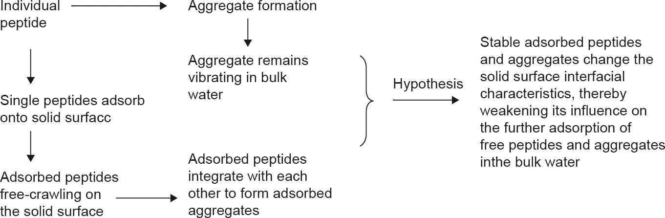
Fig. 9. The adsorption process of multiple peptides.
This research is funded by the National Key Research and Development Program of China (2016YFE0101200), the Natural Science Foundation of Jiangsu Province, China (BK20170062), the National Natural Science Foundation of China (21406148), and the Priority Academic Program Development (PAPD) of Jiangsu Higher Education Institutions. This project is also supported by the Australian Government Department of Industry, Innovation,and Science through the China-Australia Science and Research Fund(ACSRF48154)and is conducted as a part of the research program of the China-Australia Joint Research Centre in Future Dairy Manufacturing (http://acjrc.eng.monash.edu/). Jie Xiao also acknowledges the Jiangsu Innovation and Entrepreneurship(Shuang Chuang) Program and the Jiangsu Specially-Appointed Professors Program. The authors would like to express their gratitude to Nguyen Khai Ho for polishing the language of this article.
Compliance with ethics guidelines
Ruosang Qiu, Jie Xiao, and Xiao Dong Chen declare that they have no conflict of interest or financial conflicts to disclose.
杂志排行
Engineering的其它文章
- Fabrication and Mechanical Testing of Ultralight Folded Lattice-Core Sandwich Cylinders
- Thermal and Mechanical Properties Optimization of ABO4 Type EuNbO4 By the B-Site Substitution of Ta
- Efficient Nanostructuring of Isotropic Gas-Atomized MnAl Powder by Rapid Milling (30 s)
- An Efficient Process for Recycling Nd-Fe-B Sludge as High-Performance Sintered Magnets
- Tunable In-Plane Anisotropy in Amorphous Sm-Co Films Grown on(011)-Oriented Single-Crystal Substrates
- Neutron Diffraction Investigation of the DyFe11Ti Magnetic Structure and Its Spin Reorientations