Fabrication and Mechanical Testing of Ultralight Folded Lattice-Core Sandwich Cylinders
2020-05-22WanxinLiQingZhengHualinFanBinJi
Wanxin Li, Qing Zheng*, Hualin Fan*, Bin Ji
a State Key Laboratory for Disaster Prevention and Mitigation of Explosion and Impact, Army Engineering University of PLA, Nanjing 210007, China
b Research Center of Lightweight Structures and Intelligent Manufacturing,State Key Laboratory of Mechanics and Control of Mechanical Structures,Nanjing University of Aeronautics and Astronautics, Nanjing 210016, China
c Aerospace System Engineering Shanghai, Shanghai 2011089, China
Keywords:
A B S T R A C T In this research, two novel folded lattice-core sandwich cylinders were designed, manufactured, and tested. The lattice core has periodic zigzag corrugations, whose ridges and valleys are directed axially or circumferentially.Free vibration and axial compression experiments were performed to reveal the fundamental frequency, free vibration modes, bearing capacity, and failure mode of the cylinder. A folded lattice core effectively restricts local buckling by reducing the dimension of the local skin periodic cell,and improves the global buckling resistance by enhancing the shear stiffness of the sandwich core. The cylinders fail at the mode of material failure and possess excellent load-carrying capacity. An axially directed folded sandwich cylinder has greater load-carrying capacity, while a circumferentially directed folded sandwich cylinder has higher fundamental frequencies.These two types of folded lattices provide a selection for engineers when designing a sandwich cylinder requiring strength or vibration. This research also presents a feasible way to fabricate a large-dimensional folded structure and promote its engineering application.
1. Introduction
Carbon-fiber-reinforced composite (CFRC) anisogrid stiffened cylinders and lattice truss sandwich cylinders are lightweight,but have high load capacity and great rigidity. In recent years,these structures have been increasingly accepted for use in aerospace applications. Vasiliev et al. [1] reviewed the development of anisogrid composite lattice structures and their application in aerospace. Lovejoy and Schultz [2] developed the CFRC flutedcore sandwich cylinder,which may be used in large-diameter cryogenic tanks for rockets. Researchers from China [3-11] developed CFRC lattice-core sandwich cylinder technology,and demonstrated that these structures are stronger and stiffer than a typical stiffened cylinder. They also developed cylinders with a corrugated core or bi-directional corrugated core [12,13], and concluded that the corrugation design enlarges the node area and improves the shear strength. Sun et al. [14] and Li and Fan [15] developed a multi-failure criterion for both lattice-stiffened and lattice-core sandwich cylinders. Recently, Li et al. [16] and Wu et al. [17]designed and made hierarchical anisogrid cylinders,which possess excellent mechanical performance.
Fold-core sandwich structures,which are regarded as a promising alternative to conventional lightweight honeycomb sandwich structures, have many potential applications in aerospace, such as for the aircraft fuselage barrel, rocket interstage, and cryogenic tank. Cai et al. [18] discussed foldable structures in a cylindrical shape via the quaternion rotation sequence method and assessed the rigid foldability. Zhou et al. [19] developed a geometrical design protocol for a cylindrical fold-core sandwich structure based on the vertex method,and demonstrated that fold-cores outperform honeycomb cores in axial compression and radial crush but have a lower radial stiffness when subjected to internal pressure. Xiong et al. [20] and Yang et al. [21] fabricated sandwich cylinders with longitudinal and circumferential corrugated cores with a diameter of 116 and 142 mm, respectively, and demonstrated that cylindrical shells with longitudinal cores have better energy absorption ability than those with circumferential cores.Liu et al. [22] fabricated a CFRC cylindrical fold-core sandwich structure with a diameter of 156.6 mm,and demonstrated through theory and tests that its load-bearing capacity is several times higher than the traditional grid-stiffened cylinder. According to this research, the most important failure modes of these cylinders are local buckling and face crushing, which were frequently observed during the experiments.
In the present research, two novel CFRC folded lattice-core sandwich cylinders are designed. Their fabrication methods are put forward,and free vibration and axial compression tests are carried out to investigate their mechanical properties.
2. Topology design of a folded lattice-core sandwich cylinder
The sandwich cylinder includes two carbon-fiber-reinforced polymer(CFRP)skins and a lattice-core layer composed of cylindrical folded cells.The direction of the folded core has contrary effects on the strength and rigidity.Therefore,it is important to design the folded core properly according to the different load conditions.For load-bearing engineering structures,the folded core needs to have a higher strength and rigidity in the axial direction,while for structures that need a higher free vibration frequency, the folded core should possess high stiffness in the circumferential direction.
To meet the requirements of different applicative demands,two sandwich cylinders are designed: an axially directed folded sandwich cylinder(AFSC)and a circumferentially directed folded sandwich cylinder (CFSC). In the AFSC, the core is formed with an axially directed folded lattice cell, which periodically repeats both circumferentially and longitudinally along the cylindrical shell surface.In the CFSC,the core is formed with a circumferentially directed folded lattice cell.
2.1. Axially directed folded lattice cell
The topology of the axially directed folded lattice cell is illustrated in Fig.1[23].Six parameters are defined in the flat unit cell[23]: a1, a2, b1, b2, φ1, and φ2, with the stipulation that a1< a2,b1
2.2. Circumferentially directed folded lattice cell
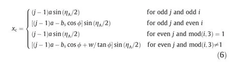
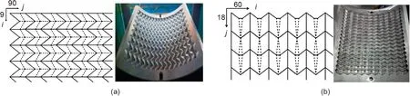
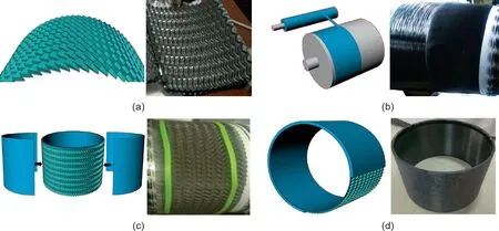
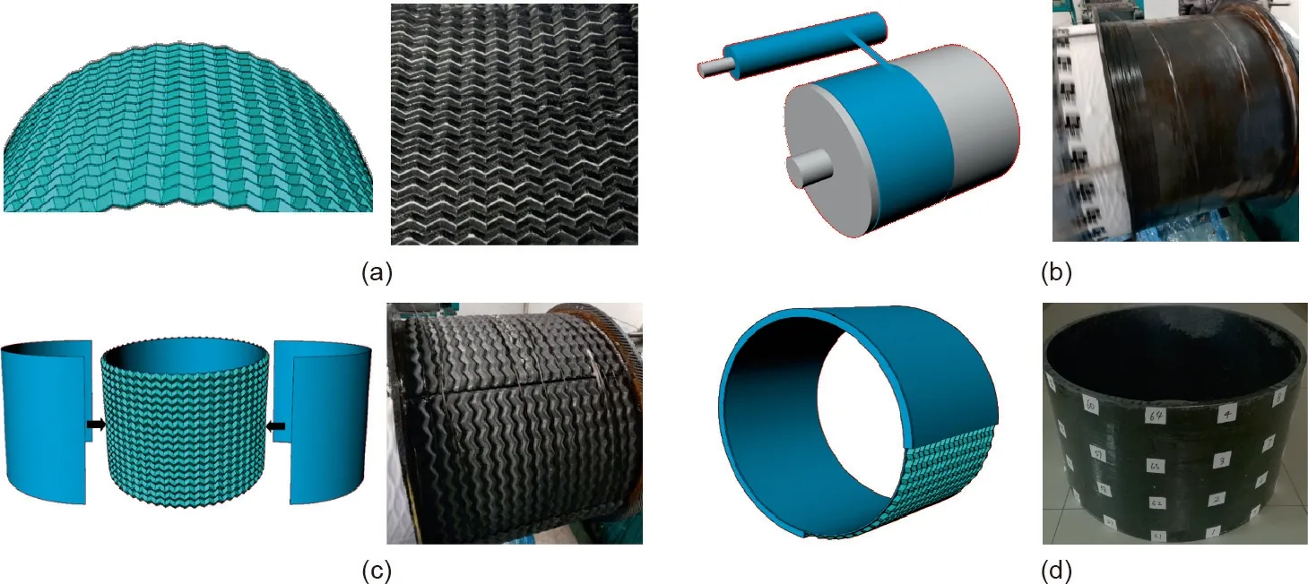
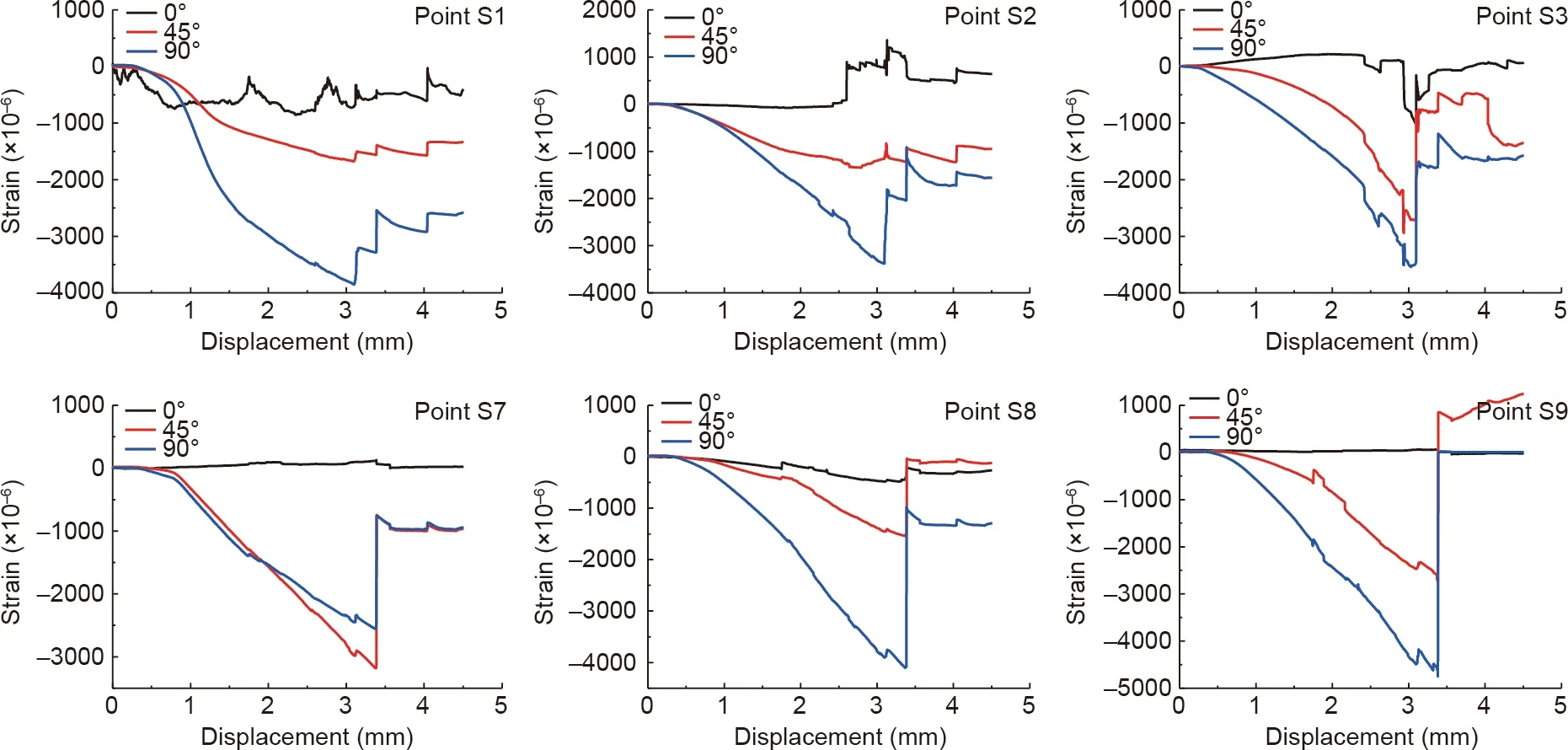
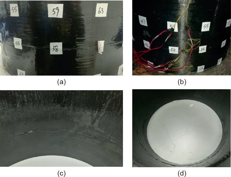
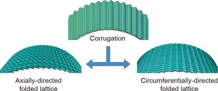
The topology of the circumferentially directed folded lattice cell is illustrated in Fig. 2 [23]. Unlike the axially directed folded cell,according to the Kawasaki-Justin theorem [23], it is not a flatfoldable pattern. Furthermore, eight parameters are defined in the flat unit cell:a, w, bl, bs, φl, φs, φm, and φ, with the stipulation that bl In the same way as described for the axially directed folded cell,ηAand ηZare the edge angles. Two parameters are defined in the front projection: the half center angles of related vertices ζ and ζk,where the vertices lie along the arc of radius R3and R4,as shown in Fig.2[23].It also has a single DOF.The relationships among the geometrical constants are deduced and given by the following: Fig. 1. The axially directed folded lattice cell. (a) Crease pattern and constants; (b) configuration variables; (c) front (r-θ) projection. r is the polar axis; θ is the polar angle[23]. Fig.2. The circumferentially directed folded lattice cell.(a)Crease pattern and constants;(b)folded configuration;(c)side(r-θ)projection.ζ is half the angle of bl side;x is the axis orthogonal to the ridge and the valley [23]. The coordinates of the controls points are given by the following: where j is the control point number in the direction of x; rcis the radius of the arc where the control point is located. where θcis the angle of control point in side(r-θ)projection;i is the control point number in the direction of θ. where xcis the length orthogonal to the ridge and the valley in the crease pattern. In this research, the designed circumferentially directed folded lattice is folded out of CFRC cloth with a=12.10 mm,bl=32.14 mm, bs=35.36 mm, w=2.5 mm, φ=51°, ηA=90°,ηZ=126°, ζ=3°, ζk=0.92°, R3=301 mm, and R4=311 mm. In this research,the diameter of all the cylinders is 625 mm and the height is 375 mm; these are close to the dimensions of Kim’s stiffened cylinder[24],which is the reference for the design.Compared with Xiong’s cylinder[20],the diameter is four times larger,resulting in a more difficult manufacturing process.Two sandwich cylinders were fabricated with the two types of folded lattice cores designed above,as shown in Fig.3.The designed mass is 3.86 kg for the AFSC and 3.81 kg for the CFSC.T700/Epoxy-resin carbon fibers were applied to fabricate the cylinder. The tensile strength of the carbon fiber is 4300 MPa and the Young’s modulus is 240 GPa. The fabrication process of the AFSC is shown in Fig. 4. The process includes four main steps: manufacturing the fold-core by the hot-pressing method, manufacturing the inner skin, adhering the fold-core and inner skin, and manufacturing the outer skin. When manufacturing a fold-core, a metallic mold is first premachined according to the folded lattice geometry, as shown in Fig. 3(a). The mold is composed of two parts: a convex part and a concave part. The central angle of the molds is 60°. A preprepared 1 mm thick prepreg lay-up of [0°/90°/90°/0°]s(s represents symmetry lay-up)is put into the concave part and manually pressed tightly to prevent the fracture of fiber; next, the convex part is clenched together with the concave part, and a hot-press molding technique is applied to form six pieces of AFSC lattice with a thickness of 10 mm, respectively. The six pieces are assembled together in a subsequent process to form an integral lattice core.To ensure the continuity and integrity of the assembly, both parts of the metallic mold should have high precision, and the irregular edges of the lattice should be corrected carefully after demolding. Fig. 3. Two folded lattice cores. (a) Axially directed folded lattice; (b) circumferentially directed folded lattice. Fig. 4. Manufacturing process of the CFRC AFSC. (a) The fold-core made by the hot-pressing method; (b) the inner skin is made by filament winding and lay-up placing;(c) adhering the fold-core and skins; (d) the completed cylinder after finishing the outer skin. The manufacture of the inner skin follows this process:winding the filament [0°], placing the lay-up [90°/90°], winding the filament [0°], placing the lay-up [90°/90°], and continuing to repeat the above operations.First,the filament is wound circumferentially to form the first thin layer; next, two prepreg layers with a fiber direction along the axis of the cylinder are placed on the first layer to form the second and third thin layers. Following this, the filament is wound circumferentially outside the prepreg layers.These operations are repeated until the skin thickness reaches 1 mm, so the fiber mode of the inside skin is [0°/90°/90°/0°]s. The six premade pieces of lattice are then adhered onto the surface of the inner skin by resin to form the core of the sandwich cylinder, as shown in Fig. 4(c). In the manufacture of the outer skin, a prefabricated thin CFRP sheet is first adhered to the core to ensure the bonding strength between the core and outer skin.Next,the process is followed until the thickness of the outer skin reaches 1 mm:winding the filament[0°],placing the lay-up[90°/90°],winding the filament[0°],placing the lay-up [90°/90°], and repeating the above operations. Finally,the sandwich cylinder is cured at 100 °C for 2 h, at 150 °C for 6 h, and then gradually cooled to room temperature in 2 h. After demolding, the cylinder is as shown in Fig. 4(d), and its fiber content is about 40%. The fabrication process of the CFSC is the same as that of the AFSC, as shown in Fig. 5; the mold for the fold-core is as shown in Fig. 3(b). Through the force-hammer excitation method, free vibration experiments were performed on the two cylinders under endfree boundary conditions at the State Key Laboratory of Mechanics and Control of Mechanical Structures. During the test, the cylinder was placed on the rubber ring to simulate free vibration, as shown in Fig. 6(a). The test equipment contains a power hammer, a modal analysis system, a charge amplifier, and three acceleration sensors. The cylinder, simplified as an n-DOF system, is impacted at one point by a hammer, and its response is measured by accelerometers at three fixed points.Moving the excitation point from point 1 to point 64 and keeping the response points fixed, the system’s frequency response function matrix can be measured;the natural frequencies and vibration modes can then be obtained. Fig. 5. The manufacturing process of the CFRC CFSC. (a) A fold-core made by the hot-pressing method; (b) inner skin made by filament winding and lay-up placing;(c) adhering the fold-core and skins; (d) the completed cylinder after finishing the outer skin. Fig. 6. Free vibration test (a) scheme and (b) frequencies and damping of the cylinders. Fig. 7. Free vibration modes of (a) the AFSC and (b) the CFSC. Freq: frequency; Damp: damping. The first 10 orders of natural frequencies are displayed in Fig. 6(b), and the modes are depicted in Fig. 7. For the first mode,the cylinder vibrates circumferentially from a circle to an oval, as shown in Fig. 7. Along the longitudinal direction, the cylinder has an identical motion phase. The second mode has an identical frequency as the first order, while their vibration shapes are along two orthogonal directions. The third and fourth orders have two circumferential waves and one longitudinal wave. The motions of the two cylinder ends have a phase difference of 180°. After that,the mode shape of the cylinder extends to form a triangular shape and a rectangular shape with higher frequency,as shown in Fig.7.The rule of the lobe development is consistent with that of a uniform thin-walled cylinder. As compared in Fig. 6(b), the first-order natural frequency is 66.01 Hz for the AFSC and 84.28 Hz for the CFSC.All the natural frequencies of the CFSC are higher than the corresponding frequencies of the AFSC, indicating that the CFSC has greater circumferential rigidity and is preferable for the design of vibration control. Fig. 8. (a) Compression experiment and (b) displacement curve for the CFRC AFSC. The axial compression behaviors of the cylinders were tested on an American brand of testing machine(MTS)universal test system at a loading rate of 0.2 mm·min-1, as shown in Fig. 8(a). Twelve strain rosettes were adhered to the outer surface of the cylinder,as shown in Figs. 6(a) and 8(a). Each strain rosette contains three gauges to measure the strains directed along the cylinder (90°),around the cylinder (0°), and along the diagonal direction (45°). The compression curve of the AFSC is displayed in Fig. 8(b). As the load increased, a small cracking sound caused by the debonding between the skin and the core could be heard near the end of the elastic deformation phase. When the displacement reached 3.28 mm, the load reached its peak value, 293.4 kN. Brittle failure then occurred in the cylinder, and the load dropped abruptly. The axial compression rigidity was 123.5 kN·mm-1. The measured strains are displayed in Fig. 9. At failure, the maximum strain appeared at the lower end; its value was 4750 με. The strain distribution for a cylinder is not ideally uniform,and failure always initiates somewhere with defects or stress concentrations. For the AFSC, the failure was located near the ends and the fractures extended around the cylinder, as shown in Fig. 10.No buckling was observed in the test, and the cylinder failed with facesheet crushing. The compression curve of the CFSC is displayed in Fig. 11(b).A small cracking sound caused by the debonding between the skin and the core was again heard near the end of the elastic deformation phase.Subsequently,the cylinder approached its peak force when the displacement was 2.79 mm, and then entered into post-failure deformation, as shown in Fig. 11. Therefore, the CFSC has better ductility than the AFSC under axial compression. The failure load of the CFSC was 191.0 kN,which is much smaller than that of the AFSC. The axial compression rigidity was 113.4 kN·mm-1, which is also smaller than that of the AFSC. In comparison with Kim’s stiffened CFRC cylinder with a diameter of 625 mm,height of 368 mm,and weight of 3.24 kg[25],the failure load of the CFSC is about 1.5 times higher, as shown in Fig. 11(b), while that of the AFSC is about 2.5 times higher. The axial rigidities of both the CFSC and AFSC are much higher. The measured strains are displayed in Fig. 12. At failure, the maximum strain appears at the upper end with a value of 3949 με, a little smaller than the value of the AFSC. The failures are located at one third of the height from the lower end,and the fractures extend around the cylinder,as shown in Fig.13.The cylinder also fails with facesheet crushing. The two cylinders have an identical facesheet, such that the peak force depends on the direction of the folding. The shear modulus is much higher along the ridge and the valley than orthogonal to the ridge and the valley, as is the bending rigidity.These contributions to the integral rigidity and the shear rigidity improve the global buckling resistance induced by bending or core shear. The corrugation also has a greater axial compression strength along the ridge and the valley than orthogonal to the ridge and the valley. When the ridges are axially directed, all these factors make important contributions to the load bearing. When the ridges are circumferentially directed, the wave core makes little contribution to the axial load bearing. Therefore, the AFSC is preferable in terms of strength design. Fig. 9. Strain curves of the CFRC AFSC. Fig. 10. Failure mode of the CFRC AFSC. (a,b) Facesheet crushing at upper edge;(c,d) facesheet crushing at lower edge. In comparison with a corrugated-core sandwich cylinder[25],a folded sandwich cylinder transforms the straight corrugation into two types of zigzag corrugation, as shown in Fig. 14. This change in geometry alters the mechanical performance. According to the structural characteristics, straight corrugation has the highest axial rigidity, and can have a high mass efficiency under axial compression. By transforming the straight corrugation into zigzag corrugation,the axial rigidity is redistributed in the circumferential direction;thus, the axial rigidities of the three structures are ordered as follows, from largest to smallest: straight corrugation, axially directed folded lattice, and circumferentially directed folded lattice. The axial load-bearing ability is positively correlated with the axial rigidity,so the failure loads of these three structures under axial compression are ordered as follows, from largest to smallest:straight corrugation,axially directed folded lattice,and circumferentially directed folded lattice,when they fail at the same mode,material yielding,or buckling.As shown in the test result,the failure load of the sandwich cylinder with a core of axially directed folded lattice is 293.4 kN, so it is much stronger than the cylinder with a core of circumferentially directed folded lattice,whose failure load is 191.0 kN.With higher axial rigidity,the welldesigned sandwich cylinder with a straight corrugation core,diameter of 625 mm,height of 375 mm,and weight of 3.24 kg has a failure load of 415.6 kN, which is much higher than those of the two fold-core cylinders [25]. Fig. 11. (a) Compression experiment and (b) displacement curve for the CFRC CFSC. Fig. 12. Strain curves for the CFRC CFSC. Fig. 13. Failure mode of the CFRC CFSC. (a,b) Facesheet crushing at outer skin;(c,d) facesheet crushing at inner skin. Fig. 14. Transformation of straight corrugation into zigzag corrugation. The circumferential rigidities of the three structures have an opposite relationship with the axial rigidities, as follows: circumferentially directed folded lattice > axially directed folded lattice>straight corrugation.Their free vibration frequencies have complex connections with both the axial rigidity and circumferential rigidity, but the frequencies are more closely connected with the weak rigidity when the anisotropy of rigidity is strong.Furthermore, for the zigzag corrugation, the shear resistance is anisotropic. The shear modulus is much higher along the ridge and the valley than orthogonal to the ridge and the valley,as is the bending rigidity. When the folded lattice is circumferentially directed, the higher shear stiffness can improve the rigidity of the sandwich shell by reducing the shear-induced deflection,which is an important contribution to the integral deflection of the sandwich structure. In addition, its bending rigidity makes a non-ignorable contribution to improve the integral rigidity.Therefore,the natural frequencies of the CFSC are much higher than those of the AFSC,as validated by the test result. It can be predicted that the cylinder with a straight corrugation core in Ref. [25] would have lower natural frequencies than both the CFSC and AFSC. Other than improving the fundamental frequency, there are other advantages for folded lattice-core cylinders. First, adopting zigzag corrugation can restrict the local buckling of the facesheet,while this failure mode was often observed in axial compression of the straight-corrugated-core sandwich cylinder [25]. Second,zigzag corrugation also enhances the shear resistance by increasing the bonding area compared with straight-corrugated-core cylinders, and improves the global buckling resistance. Third, the folded lattice-core sandwich has an open configuration, so the cylinders would have the property of air permeability, which can meet the requirements of some multi-function designs, especially in aerospace engineering. The fabrication of the cylindrical folded lattice core in this research is easy to achieve, which might be the key to promote the engineering application of the folded core sandwich cylinder.Liu et al. [22] fabricated a CFRC cylindrical fold-core sandwich structure using the mold-pressing method and that structure has excellent mechanical properties, although the fabrication method would be limited in the case of a larger cylinder design.In the present research, the integral fold-core was split into six identical parts. Each part was manufactured by hot-pressing using metallic molds. This method is now easy to realize. Furthermore, the use of filament winding and lay-up placing to make the cylindrical facesheet is a mature technique. Therefore, the present research presents a successful and feasible way to make a largedimensional folded structure and promote its engineering application.Aspects that remain to be improved are the fiber content and the pressure control in the curing process. In this research, two novel folded lattice-core sandwich cylinders with two types of cores were designed and fabricated. Their free vibration and axial compression behaviors were investigated through tests. The following conclusions were made: (1) The manufacturing process of the CFRC fold-core sandwich cylinder was realized through mold-pressing, filament-winding,and lay-up placing techniques. By fabricating six repeated pieces of the lattice and assembling them to form an integral core layer,it is feasible to create large-dimensional folded lattice-core cylinders. (2) The zigzag topology of the corrugation in the folded lattice enhanced the shear resistance of the core by increasing the bonding area with the skins, and improved both the global and local buckling resistance. The AFSC and CFSC have different advantages in terms of mechanical properties due to their geometric characteristics, resulting in wider potential applications in engineering. (3) Both the AFSC and CFSC freely vibrate like typical short sandwich cylinders, with the modes changing from oval, to triangular, to quadrangular. The CFSC has higher circumferential rigidity and shear stiffness, leading to higher natural frequencies than the AFSC,so the CFSC is preferable when designing structures with strict frequency requirements. (4)In the axial compression test,both the AFSC and CFSC failed at the facesheet crushing mode; however, their bearing capacities differed because of the different folding directions of their cores.Due to its higher rigidity in the axial direction, the AFSC has a greater peak load under compression, so it is preferable in terms of strength design. Support from the National Natural Science Foundation of China(11672130 and 11972184), the State Key Laboratory of Mechanics and Control of Mechanical Structures (MCMS-0217G03), and Aerospace System Engineering Shanghai are gratefully acknowledged. Help from Professor Tong Wang in vibration testing is gratefully acknowledged. Wanxin Li, Qing Zheng, Hualin Fan, and Bin Ji declare that they have no conflict of interest or financial conflicts to disclose. The relationships among the geometrical constants of the axially directed folded lattice were deduced by Gattas et al. [23] and were used to design the cylinder; they are cited below: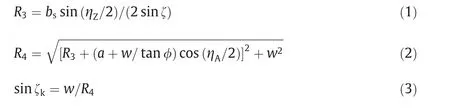


3. Fabrication
3.1. The axially directed folded sandwich cylinder
3.2. The circumferentially directed folded sandwich cylinder
4. Free vibration behaviors


5. Axial compression behaviors


6. Discussion
6.1. Mechanical behaviors


6.2. Evaluation of fabrication method
7. Conclusions
Acknowledgement
Compliance with ethics guidelines
Appendix A

杂志排行

Engineering的其它文章
- Multi-Peptide Adsorption on Uncharged Solid Surfaces:A Coarse-Grained Simulation Study
- Thermal and Mechanical Properties Optimization of ABO4 Type EuNbO4 By the B-Site Substitution of Ta
- Efficient Nanostructuring of Isotropic Gas-Atomized MnAl Powder by Rapid Milling (30 s)
- An Efficient Process for Recycling Nd-Fe-B Sludge as High-Performance Sintered Magnets
- Tunable In-Plane Anisotropy in Amorphous Sm-Co Films Grown on(011)-Oriented Single-Crystal Substrates
- Neutron Diffraction Investigation of the DyFe11Ti Magnetic Structure and Its Spin Reorientations