Fast radial scanning probe system on KTX
2020-05-06TijianDENG邓体建TaoLAN兰涛MingshengTAN谭名昇JunfengZHU朱军锋JieWU吴捷HangqiXU许航齐ChenCHEN陈晨YolbarsopADIL阿迪里SenZHANG张森JiarenWU邬佳仁YimingZU祖一鸣WenzheMAO毛文哲HongLI李弘JinlinXIE谢锦林AhdiLIU刘阿娣ZixiLIU刘子奚ZhengweiWU吴征威HaiWANG汪海Xi
Tijian DENG (邓体建),Tao LAN (兰涛),Mingsheng TAN (谭名昇),Junfeng ZHU(朱军锋),Jie WU(吴捷),Hangqi XU(许航齐),Chen CHEN(陈晨),Yolbarsop ADIL (阿迪里),Sen ZHANG (张森),Jiaren WU (邬佳仁),Yiming ZU (祖一鸣),Wenzhe MAO (毛文哲),Hong LI (李弘),Jinlin XIE (谢锦林),Ahdi LIU (刘阿娣),Zixi LIU (刘子奚),Zhengwei WU (吴征威),Hai WANG (汪海),Xiaohui WEN (温晓辉),Haiyang ZHOU (周海洋),Zian WEI (卫子安),Chijin XIAO (肖持进),2,Weixing DING (丁卫星),Ge ZHUANG (庄革) and Wandong LIU (刘万东)
1 KTX Laboratory and Department of Engineering and Applied Physics,University of Science and Technology of China,Hefei 230026,People’s Republic of China
2 Plasma Physics Laboratory,University of Saskatchewan,Saskatoon,SK S7N 5E2,Canada
Abstract
Keywords: radial scanning probe,high-speed movement,noncontact magnetic grating ruler
1.Introduction
Fast reciprocating probe systems have been widely used in tokamaks to measure plasma edge profile parameters during discharge,such as potential,electron density,and temperature profiles with high temporal and spatial resolutions [1–9].With these systems,the probes can reduce their exposure to plasma by reciprocating movement and thus minimize possible damage.It is a simple and effective means for fast reciprocating probe to measure plasma edge profile parameters.
There are two processes for the probe systems to send probe into plasma.Probe is pushed to a stand-by position before the discharge in first process.The initial probe position relative to plasma usually needs to be adjusted with a slow stepping motor because of its high accuracy.In second process,probe is fast sent into plasma by powerful thrust during the discharge.As a simple drive source,the pneumatic cylinder has often been chosen to perform the fast movement to measure plasma edge parameters on numerous plasma devices.However,for most systems,maximum velocities achieved by pneumatic cylinder are below 3 m s-1[1–5].Although the maximum speeds of the systems are large enough to reciprocate probe for the long discharge durations,the structure of pneumatic cylinder limits its largest speed.Therefore,as another driving power in now days,the servomotor with very high torque driven by the strong electromagnetic force is chosen for driving the probe system,as it easily provides powerful and precise control.For example,the fast reciprocating probe system on the EAST [6] controls the probe acceleration and deceleration movement and has a reciprocating range of 50 cm with a maximum velocity of 2 m s-1.A 75 cm linear displacement potentiometer gives an analog signal of the probe head position.The speed of 2 m s-1satisfies the reciprocating requirement of EAST.However,its probe system can develop a larger speed if increasing the torque of servo-motor.
Figure 1.Fast radial scanning probe system on KTX.
Early reversed field pinches (RFPs) [10–13] have rarely equipped with reciprocating probe due to short discharge durations.However,a plasma profile diagnostic tool is urgently needed for Keda Torus eXperiment (KTX) [14–29]RFP.According to the experiences on tokamaks,a fast scanning probe system is designed to measure the plasma edge potential,density,and temperature profiles on the KTX RFP.For KTX,the duration of discharge is very shorter than most tokamak devices and thus there is not enough time for probe to reciprocate movement.Only a fast scanning movement is proposed,however,a higher scanning speed is required.We hope the probe in the system can travel about 4 cm within 10 ms during KTX discharge.Then,a powerful servo-motor with a high-torque of 35 N m is chosen to drive the probe shaft.From the examples above,potentiometer and optical grating ruler are common displacement measurement tools.But they are easy to damage,especially in collision operation.A noncontact magnetic grating ruler is first adopted to record the fast movement displacement to avoid shock.The system tests indicate that the fast displacements are repeatable and reliable.The preliminary experimental result of the floating potential profile scanned by the system is in agreement with that of the fixed radial probe array.
The paper is organized as follows.Section 2 introduces the experimental conditions.Section 3 specifies the mechanical design of the scanning drive system.Section 4 describes the control and data acquisition systems.Section 5 gives the bench test results.Section 6 provides the preliminary experimental results,and section 7 presents the summary.
2.Experimental facilities
KTX is a medium-sized RFP device located at the University of Science and Technology of China in Hefei,China.It has a major radius of 1.4 m and a minor radius of 0.4 m,with poloidal and toroidal molybdenum limiters of 2.0 cm height.There are two phases in the development of KTX[18]:Phase 1—toroidal fieldBt= 0.35 T,plasma currentIp= 0.5 MA,electron temperatureTe= 300 eV,with a discharge pulse of 30 ms;Phase 2—Bt=0.7 T,Ip= 1 MA,Te= 800 eV,with a discharge pulse of 100 ms.Currently,KTX is under conditioning of Phase 1.The parameters achieved are:Bt= 0.25 T,Ip= 0.2 MA,Te= 100 eV,and a maximum discharge duration of 22 ms[26].The line-averaged density is=(1–2) × 1019m-3.
Several fundamental diagnostics,including electromagnetic probes [27],a 2D double-foil soft x-ray diagnostic system,a chord 650 GHz solid-state source interferometer[19,22],spectroscopy measurement of seven-channel Hαline diagnostic and bolometer diagnostic,a high-speed visible imaging system,and an array of eddy current probes [23],have been developed to measure plasma current,temperature,line-averaged density,and radiation,provide plasma shape characteristics,and study plasma instabilities.In this work,we introduce a fast radial scanning probe system,built to obtain the profiles of plasma edge density,temperature,and floating potentials within a single discharge.
3.Mechanical design
A fast radial scanning probe system is designed and installed on KTX,as shown in figure 1.The system is mounted on the midplane port with a diameter of 150 mm.The mechanical design of the scanning probe system is shown in figure 2.The system consists of two motion drive mechanisms:(1)a standby movement and (2) a fast scanning movement.
Figure 2.Mechanical design of the scanning probe system.
The stand-by movement is controlled by a stepping motor to set the initial probe position,providing a maximum stroke of 80.0 cm.In this process,the movable part goes forward along two linear guide rails and compresses long welded bellows.A probe-preparation chamber with a transparent glass port is installed behind the vacuum gate valve to observe and replace the probe.A stable and powerful hightorque servo-motor of 5.5 kW is used to drive the drive board for a fast scanning movement.Balanced counterweights are considered to balance the weight of the servo-motor and ensure that the center of gravity coincides with the center line.To obtain larger forward speeds,the servo-motor works in the torque mode,producing a maximum force of 1100 N on the module slider and drive board by transmission from a highspeed linear actuator.In figure 2,when the fast scanning movement is active,the move board and four compression strings between the drive board and the move board protect the drive board from direct collision with the braking cylinders.Strings moreover guarantee that after the move board collides with the braking cylinders and stops immediately,the drive board slows down gradually without causing damage to the servo-motor and linear actuator.Here,strings with string constant of 1600 N m-1and a natural length of 25.0 cm are chosen.The compression range spans 0–19.0 cm,and the four strings provide a maximum braking force of 1216 N,which is slightly higher than the maximum force deliverable by the servo-motor.The strings can be easily substituted if their string constants are not suitable.The drive board made of light aviation aluminum loses less energy,and,consequently,the move board acquires more power.The four axial hollow cylinders at the strings mounted on the move board ensure that the strings can be compressed vertically.There are four holes in the drive board coaxial with the four hollow cylinders and larger in diameter than the cylinders.Therefore,relative displacement between the drive board and the hollow cylinders is allowed when the speed of the drive board is larger than that of the move board.Four end covers behind the drive board,which are larger than the holes in the board connected to the four hollow cylinders by screws,are pushed backward by the drive board and thus drag the move board back to its original position after the forward fast movement is completed.A 2.05 m long stainless steel probe shaft with a diameter of 2.0 cm is connected to the probe head and the movable part.The total mass of the fast moving part is about 12.0 kg,including the probe head,probe shaft,thin-wall hollow cylinders,move board,and partial fast welded bellows.The system allows the entire radial measurement range covering half of the KTX vacuum chamber in the KTX midplane.Details regarding the motion of each part are presented in section 5.
4.Control and data acquisition systems
As mentioned above,it takes two modes of movement to move the probe into the chamber:(1)the stand-by movement and (2) the fast scanning movement.In the stand-by movement,the probe system above the support platform is driven by a stepping motor to a stand-by position before the discharge.Subsequently,the high-torque servo-motor pushes the probe into the edge region after receiving the ‘trigger’ signal from the controlling system.The two operations are carried out by two independent micro control units (MCUs),which conveniently and effectively move the probe by remote control.

Figure 3.Square signals of fast scanning movement controlled by the MCU.
In the stand-by movement,the MCU controls the probe shaft and servo-motor assembly to move forward and backward by directional signals and uniform continuous squares with a resolution of 1 mm.
In the fast scanning movement,the MCU controls the servo-motor by several adjustable square signals shown in figure 3.After the ‘trigger’ signal at t0,the servo-motor is force-free and subsequently becomes active by ‘braking release’ and ‘enabled’ signals.At W1microseconds later,the servo-motor shifts from the position mode to the torque mode by ‘torque–position conversion’,which lasts for W2microseconds.In this mode,the servo-motor pushes the probe shaft to quickly move forward,while the ‘torque input’ signal controls the acceleration and deceleration of the motor,applying the negative and positive voltages,respectively.Square widths of W3,W4,W5,W6,W7,and W8and voltages of V1,V2and V3in the ‘torque input’ signal are related to the ongoing displacement signal of the probe,which will be described in section 5.After the forward movement finishes,the probe shaft returns to the original position at t1with a continuous squares signal,controlled by the servo-motor in the position input.To ensure safety,the servo-motor is in a braking and disabled state after t1that is fed back from a limit switch.
To achieve good shock resistance ability,a noncontact magnetic grating ruler,made up of a magnetic reading head and a magnetic ruler,is used for the fast displacement measurement of the scanning probe for a high spatial resolution of 5 μm and a maximum velocity of 25 m s-1.In our initial tests,the optical grating ruler,widely used as a high-speed machine tool and in other reciprocating probe systems,has been damaged when the speed of the probe exceeds 2 m s-1.In contrast,the magnetic grating ruler can bear very high speeds and shocks without contact.The probe system is in the‘nearly zero’ magnetic field region less than 20 Gauss in the middle plane,and the discharge magnetic field influence on the magnetic grating ruler can be ignored[29].The output signals of the magnetic grating ruler are two quadrature TTL pulse time serials,which implement a minimum measurement resolution of 5 μm and determine the direction of movement.
All the probe signals are acquired by National Instrument’s 16-bit PXIe-6368 digitizer with synchronous sampling frequencies of 2 MHz suitable for the high-frequency fluctuations of plasma turbulence.The output TTL pulses of the magnetic grating ruler are digitally sampled with the same card at 10 MHz,which satisfies the minimum temporal resolution requirement of 1.25 μs at a maximum speed of 4 m s-1.The displacement of the drive board is decoded from the output TTL pulses from the servo-motor encoder.The digitizer is installed on a PXIe crate and placed very close to the probe system.Coaxial cables are used to transmit all the signals.The trigger signal and the network use the optical fiber to isolate the connections between the probe system and the center control system.
5.System test
A system test on the KTX device was conducted to obtain the movement parameters of the probe system without plasma discharge.The typical testing parameters of MCUs are W1= 200 ms,W2= 600 ms,W3= 200 ms,W4= 120 ms,W5= 5 ms,W6= 35 ms,W7= 40 ms,W8= 95 ms,V1=-10 V,V2=10 V,and V3=-5 V.The displacements and velocities of the probe shaft and drive board are decoded from the output quadrature digital signals and shown in figure 4.
There are five states presented in figure 4.State A,initial position: the initial length of the string is 25.0 cm,and the distance between the move board and the braking cylinders is 20 cm;State B,acceleration:the drive board is accelerated by the servo-motor in the torque mode at voltage V1,and then the string is compressed to provide a force to drive the probe shaft; State C,collision: the move board hits the braking cylinders and stops immediately; State D,preparation for the rebound of strings: the drive board reduces its speed to 0 m s-1by an acting force from the strings and the servomotor at voltage V2,and the length of the strings achieves a minimum value;State E,rebound end of the strings:under the acting force of the servo-motor at voltage V3,the strings rebound slowly,and the drive board slightly touches the four end covers of the axial hollow cylinders at about t=495 ms.The final state,not shown in figure 4,follows the forward movement back to the original position: the probe shaft is pulled back slowly by the servo-motor in the position mode,and the length of the strings returns to 25.0 cm,whereas the distance between the move board and the braking cylinders returns to 20 cm.
Figure 4.(a) Forward displacement signals of the probe shaft,drive board,and string length signal(the initial position of the drive board is set as the zero point of displacement).(b)Forward velocity signals of the probe shaft and drive board.
Figure 4(b) shows that the maximum velocity of the probe shaft reaches 4.0 m s-1,which means that the probe can be sent into the plasma at a distance of 4.0 cm in 10 ms during a discharge.These results are repeatable throughout numerous experiments,with a delay time and an amplitude difference of less than 0.4 ms and 0.5 mm,respectively.
These results meet users’ requirements of fast scanning edge plasma parameter profiles in KTX.In addition,the displacement and velocity are adjustable in different plasma discharge conditions by changing the width and amplitude parameters of the torque input signal from W1to W8and from V1to V3,respectively.
6.Preliminary experimental results
The plasma parameter profile,that is,the floating potential,has been measured by the scanning probe system at ultralow q discharge in KTX [26],here q is safety factor.A sturdy and durable single-tip probe is adopted in this study,as shown in figure 5.The material of the probe tip is made of stainless steel,which is suitable for low-temperature plasma.The single probe tip has a diameter of 3.0 mm and a length of 2.0 mm.The single tip is surrounded by the Al2O3ceramic tube and is exposed to plasma.A polytetrafluoroethylene(PTFE)ring is placed behind the ceramic tube to avoid strong shocks.The elastic PTFE tube 1 and PTFE tube 2 with steps squeeze probe tip to ensure that the stainless steel tip does not damage the two tubes as it shakes in the direction of its movement.At the same time,the measurements of floating potential profile with rake probe array of nine tips are compared with the measurements with reciprocating single-tip probe.The rake probe is composed of graphite tips,a shield,a boron nitride base,and a stainless steel support,as shown in figure 6.Each probe tip has a diameter of 1.5 mm and a length of 2.0 mm.The radial distance between two adjacent tips is 5.0 mm,and the total radial coverage is 4.0 cm.
Figure 5.Cross-sectional drawing of a single-tip probe for the scanning floating potential profile and schematic of its circuit.
Figure 7 shows the floating potential profile scanned by the single-tip probe in shot 11301.According to the probe position signal,the probe travels more than 5.0 cm during a discharge.In figure 7(c),the evolution of the plasma floating potential at radial position r = 35.0 cm measured by one of the radial rake probe tips in another shot 11 540 is depicted by the red line.The floating potential Vfis flat at the temporal scale of the single-tip traveling,which suggests that the plasma floating potential profile is invariable,even though the plasma current falls.An obvious gradient is visible in Vfafter 6 ms in figure 7(c)(blue line),which clearly corresponds to a radial position of 38.0–37.0 cm in figure 8 (blue line).The floating potential becomes flatter as the probe is inserted deeper.Sudden changes occur after 12 ms in Vf,possibly due to the instability of the plasma geometry center.In figure 8,red squares with error bars depict the mean floating potential signals with 11 shots,measured by the fixed radial probe array.The data in each shot at a certain position are averaged over a time window of 0.4 ms.From these results,we can conclude that the profiles from the two measurement methods are in agreement.
The data analyzing techniques will be mentioned here.In our device,the relationship of electron mean free pathλmfp,Debye lengthλDand probe characteristic size h isλmfp≥h≥λD,h is the height of probe tip,and meets the conditions of traditional thin sheath theory.For the single probe’s I–V trace,the stray capacitance Cstrayin the coaxial cable limits the highest sweep frequency on KTX.The toroidal magnetic field Btis large enough to reduce collecting ion and electron saturation current.The ion and electron almost travel parallel to the magnetic field lines and we consider collecting ion current area Aisand electron current area Aesas Ais=2φh and Aes=RAp,here φ is the diameter of probe tip,Apis the superficial area of probe tip and R is correction coefficient,R≪1.The Btis strong and thus electron temperature Tecalculated using transition part near the electron saturation region of I–V curve will result in large error.Even so,the region near floating potential in transition part and ion saturation current Iisare basically not influenced.Then,electron density neis measured by ion saturation current Iisand electron temperature Tecan be measured by the transition area near the floating potential of I–V curve.
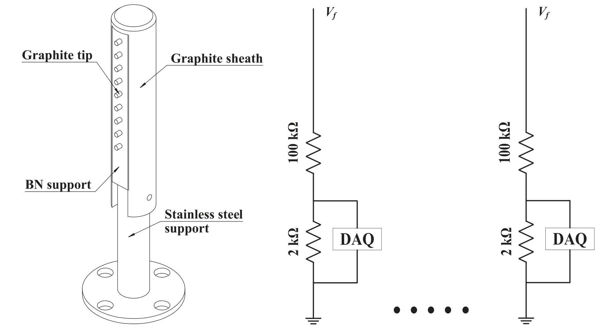
Figure 6.Radial rake probe array measuring the floating potential profile at a number of fixed positions and schematic of their circuit.

Figure 7.Evolution of(a)plasma current Ip,(b)probe position r,and(c) floating potential Vf.

Figure 8.Comparison of floating potential measurements from a single-tip probe and a radial rake probe array.
We use the single probe,shown in figure 5 and fixed at the radial positon r = 36 cm,to obtain the I–V trace.In the discharge flattop,the single probe’s I–V trace is measured by applying the ramp voltage sweep Usweepat a frequency of 5 kHz with the circuit in figure 9 and the result is shown in figure 10.The d2I/dU2,shown in figure 11(a),is also calculated by the transition part of I–V curve fitted with a polynomial.From the d2I/dU2curve,we consider that the Electron Energy Distribution Function (EEDF) satisfies the single-Maxwellian distribution.Furthermore,a linear relation exists between ln(I + Iis) and Usweep,shown in figure 11(b).Therefore,we neglect hot electrons influence and there is no bi-Maxwellian effect in our plasma.
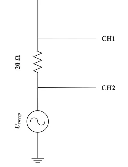
Figure 9.The sweep circuit of the single probe’s I–V trace.
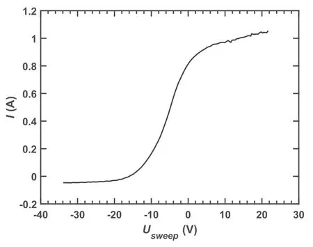
Figure 10.The result of the I–V trace using the single probe.
The plasma floating potential Vf,the electron temperature Te,ion saturation current Iis,and electron density nehave been measured by a typical four-tip probe fixed at a radial position r = 36 cm,mounted on this probe system.Two floating potentials in the four-tip probe are put along poloidal direction with a distance ofΔθ= 7 mm.The probe structure and the circuit are presented in figure 12.The graphite probe tip has a diameter of φ = 2.0 mm and a radial height of h = 2.0 mm.The basic plasma parameters measured by the probe are shown in figure 13.The temperature and density are calculated aswhereα= 0.61,e is electron charge,andCsis ion sound speed.The plasma instability is measured by both the saturation current and the floating potential.As low temperature plasma on KTX so far,electron temperature fluctuationis small and conventional treatment is to neglect the fluctuation [30],i.e.hereare the fluctuations of electron density,ion saturation current,plasma potential,and plasma floating potential.The plasma profiles measured by the four-tip probe with fast scanning will be carried out in further experiments.

Figure 11.The curves of (a) d2I/dU2 and (b) ln(I + Iis)–Usweep relation in transition part of I–V trace.
7.Summary
The fast radial scanning probe system built for KTX can quickly position the probe from the edge to the core of the chamber.The stepping motor slowly moves the system to an initial stand-by position,and then the high-torque servomotor applies the large drive force for fast probe scanning of the plasma boundary parameters.A special string design prevents the drive board from strongly punching on braking,to protect the servo-motor.Its temporal control system using the MCUs is very convenient and effective in triggering the probe remotely.The maximum speed of the fast scanning system reaches 4.0 m s-1,which basically satisfies the profile measurement requirement for the KTX discharge.To avoid vibrations,a noncontact magnetic grating ruler of high spatial resolution (5 μm) and a maximum speed of 25 m s-1is used for the position and velocity measurements.The synchronous sampling rates of the data acquisition system are at 2 MHz for analog and at 10 MHz for digital measurements,which are appropriate for the high-frequency fluctuations of plasma turbulence and fast scanning displacement measurement.The test results indicate that the fast displacements are repeatable and reliable.Furthermore,a comparison of the plasma floating potential profiles obtained by the fixed radial rake probe and the scanning single probe suggests that the high-speed scanning probe system is suitable to measure the edge plasma parameter profiles with a single shot.Moreover,the highspeed feature of the scanning probe system is particularly suitable for devices similar to KTX with very short discharge durations.

Figure 12.The sketch and the circuit of the four-tip probe.
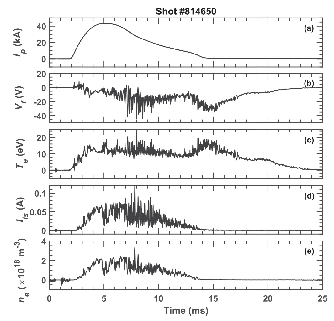
Figure 13.Basic plasma parameters of (a) plasma current Ip,(b) the plasma floating potential Vf,(c) the electron temperature Te,(d) ion saturation current Iis,and (e) electron density ne.
Acknowledgments
This work was supported by the National Magnetic Confinement Fusion Science Program of China (No.2017YFE0301700)and National Natural Science Foundation of China (No.11635008).
ORCID iDs
猜你喜欢
杂志排行

Plasma Science and Technology的其它文章
- Preliminary design of high power magnet converter for CRAFT
- Design and control of coaxial switching system for ion cyclotron wave resonance heating system of EAST
- Estimation of plasma density perturbation from dusty plasma injection by laser irradiation on tungsten target in DiPS
- Investigation on plasma characteristics in a laser ablation pulsed plasma thruster by optical emission spectroscopy
- A two-dimensional air streamer discharge model based on the improved Helmholtz equation at low temperature and sub-atmospheric pressure
- Mode transition induced by gas pressure in dusty acetylene microdischarges: twodimensional simulation