Installing a prototype wind turbine to produce energy in Antarctica to allow a permanent Colombian scientific base to be established
2020-04-12CesarLozanoJIMENEZ
Cesar Lozano JIMENEZ
1 Conceptual Design of a UAV type VTOL (FAC-USB),Department of Aeronautics,Graduate Program in Aeronautical Engineering,San Buenaventura University (USB),Cr 8H # 172-20,Btá D.C,Cund,6671090,Colombia;
2 Administration of Aeronautical Maintenance Personal (FAC-EPFAC)/Department of Aeronautical Logistics,Graduate Program in Specialist Aeronautical logistics,Postgraduate School of Colombian Air Force University (EPFAC),Cr11 102-50 P 3 4 Ed Esdegue,Btá,6206518,Colombia
Abstract This study was performed to support an expeditionary team of Colombian scientists seeking to promote and undertake research in various scientific fields in Antarctica.The work was part of the Colombian Antarctic Program,which comprises various projects intended to lead to a permanent Colombian scientific base being established in the Antarctic.The first step involved installing a Colombian-made wind turbine to produce electricity at a permanent base.The aeolian turbine was designed to provide sufficient electricity to illuminate and heat a small base.The turbine was constructed using readily accessible materials but taking the Madrid Protocol environmental regulations into consideration.The project was performed at the Argentinian Antarctic Marambio Station on Seymour Island,off the Antarctic Peninsula.An initial field study performed in 2015 was the first of three phases of the project.In the initial phase,local meteorological data were gathered to support development of a prototype turbine and to allow a design to be selected that was robust enough for the extreme environmental conditions.The wind turbine was then constructed in Colombia.The second phase involved transporting the turbine to Antarctica and installing it at the Marambio Station in 2018.Finally,the physical conditions of structural and electronic components of the turbine were carefully inspected at the beginning of 2020 (after the turbine had operated continually for ~2 years) to allow repairs to be made and any necessary re-engineering to be performed.
Keywords wind energy,renewable energy,Marambio Station,Seymour Island,Colombia Antarctic Program
1 Introduction
This project was proposed to support the ambition to establish a permanent Colombian scientific base on the Antarctic continent.The aim was to support the ambition from the logistic and engineering perspectives by developing a clean source of electrical energy in full compliance with environmental agreements (Cañete,2017).
Wind is considered to be the most suitable source of renewable energy for exploiting in the Antarctic.It was stated in the Kyoto Protocol and in the Sustainable Development Goals that generating power from wind energy can help mitigate climate change and will play a crucial role in modulating the climate at the local and regional level.Importantly,wind currents will become stronger as global temperatures increase (Harvey,2019).
Greenhouse gas emissions also represent an increasingly important problem owing to particle exchange through land–atmosphere–ocean interactions that can transfer toxic and polluted substances between organic and inorganic forms of life while deteriorating aquatic ecosystems (Peters et al.,2020).There is an increasing amount of evidence to suggest that C cycling and CO2contamination have severe impacts on many ecosystems.
The project methodology was developed in three phases.The first phase consisted of collecting data on meteorological metrics such as wind speed and temperature,determining the expected energy consumption,and identifying materials suitable for use at an Antarctic station.Review of the potential supply chain and associated logistics required consideration of the project location and establishment of cooperative agreements regarding transport,facilities,and mission operation.
In the second phase,the prototype FAC-X-001 wind turbine was transported to the Marambio Station in Antarctica for installation and testing (Comunicaciones Estratégicas Fuerza Aérea,2018).
During the third phase,nondestructive testing was performed,which included detailed visual inspection and the use of infiltrating dyes and ultrasound techniques to assess the integrity of both the structure and the electronics of the wind turbine.
The various phases of the project conducted at the Marambio scientific station,operated by the Argentine Air Force,were undertaken between 2015 and 2020 in campaigns with duration of up to two months.
The Colombian ambition to establish a presence in the Antarctic by deploying a scientific station will provide the opportunity to address a diverse range of questions,e.g.:“How can energy be supplied in a remote location under extreme weather conditions while being environmentally friendly?” This challenging problem must be resolved to support the objective of the Colombian government of first establishing a seasonal Antarctic scientific station,then building a permanent camp by 2035,at which emergent scientific experimentation and innovation research will be performed.
In collaboration with the Argentine Air Force and the National Directorate of Antarctic Affairs of Argentina,and with the sponsorship of the Colombian Air Force and the Colombian Ocean Commission,the project for deployment of the first wind turbine manufactured in Colombia at the Marambio scientific station in the Antarctic in 2019 was conceived.In managing the project successfully,the supporting organizations funded the construction of the prototype,provided logistical support,and furnished the operational team in the Antarctic with transport,utilities,shelter,tools,and supplies.
2 Initial phase—Antarctic field campaign
2.1 Planning
The first excursion to Antarctica,which was in 2015,had the objectives of collecting data,analyzing information,and developing an understanding of the background in the field of study to support the subsequent project steps,in combination with assessing both the tool requirements and the technical plans that would require development during the study (Table 1).
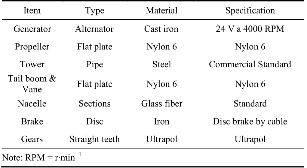
Table 1 Technical features of the wind turbine (Jimenez,2018)
In this stage,the following factors were evaluated regarding implementation of a wind turbine generator as a source of energy production in the Antarctic:(1) logistics and supply chain conditions,(2) electricity requirements,e.g.,energy consumption by necessary operational devices,(3) meteorological metrics,e.g.,wind and temperature,and (4) local groundwork required for turbine installation.
2.2 Data collected
Time series of wind speed and temperature data recorded at the Marambio scientific station during the initial phase in December 2015 of the project are illustrated in Figure 1 (maximum wind speed registered of 80.6 km·h-1and average of 30 km·h-1) and Figure 2 (maximum temperature registered of-17.6 ℃ and average of-10 ℃,respectively).
2.3 Preliminary calculations for design of the wind turbine
To determine the expected energy consumption and to comply with the baseline energy production,the energy requirements of the electronic components that are fundamental to supporting a scientific team must be considered (Table 2),and the parameters regarding energy production must be established (Table 3).

Figure 1 Wind speed versus check points at 30-min intervals from 25 February to 7 March,2018 (Jimenez,2018).

Figure 2 Temperature versus check points at 30-min intervals from 25 February to 7 March,2020 (Jimenez,2018).

Table 2 Electronic devices and their estimated energy consumption presented by researcher (Jimenez,2018)

Table 3 Estimates regarding energy generation (Jimenez,2018)
The power that can be obtained from a wind turbine can be determined using the following expression:

wherePis power output (W),Cpis maximum power coefficient (range:0.25–0.45 and theoretical maximum:0.59 (nondimensional)),ρis air density (kg·m-³),Ais rotor swept area (m² or πD²/4,whereDis rotor diameter (m)),π is 3.1416,andVis wind speed (m·s-1) (Table 4).

Table 4 Input parameters for turbine design (Jimenez,2018)
Based on Eq.(1) and the information listed in Tables 1–3,it was concluded that the baseline energy requirement could be serviced by a 6-kW generator.
2.4 Design
2.4.1 Aerodynamics
The prototype horizontal three-bladed wind turbine with a flat plate profile was installed in Antarctica and subjected to materials elasticity tests,component behavior assessment,and mechanical analysis.In construction of the prototype,the wind intensity at the target location was analyzed and considered in conjunction with several other parameters and a set of more sophisticated aerodynamic configurations.
The three-bladed form was designed to be sufficiently robust to the extreme conditions of subzero temperatures,strong winds,and high levels of corrosion.
The desired outcome was for an adequate supply of electricity generated by a simple wind turbine delivering exceptional performance at minimal cost,without need for specialized devices.Interpretation of the compiled data suggested that simplicity was appropriate considering the expected wind speed,denoted significant energy,and that specific improvements to achieve ideal speeds or optimum mechanical capabilities were unnecessary.
Mechanical noise mitigation was incorporated into the configuration of the structure.The three blades configuration were set to minimize the effects of the cyclic and repetitive movement of spinning,air cut off,and the shock effect of wind against the mechanical assembly to produce low noise levels and mechanical resonance;otherwise,the risk of material failure through fatigue fracture could have been increased (Yamada,1998).
Generally,blades with a definite twist are more efficient because the lift and drag become closer to optimal levels (Figure 3);however,cost implications mean that most blades cannot be twisted.In areas that require high effectiveness,the offset loss in performance of a flat blade should be considered (Johnson,1985).
Average surface wind speeds globally are depicted in Figure A1.It can be seen that Antarctica has some of the strongest surface winds on the planet (Figure A2).
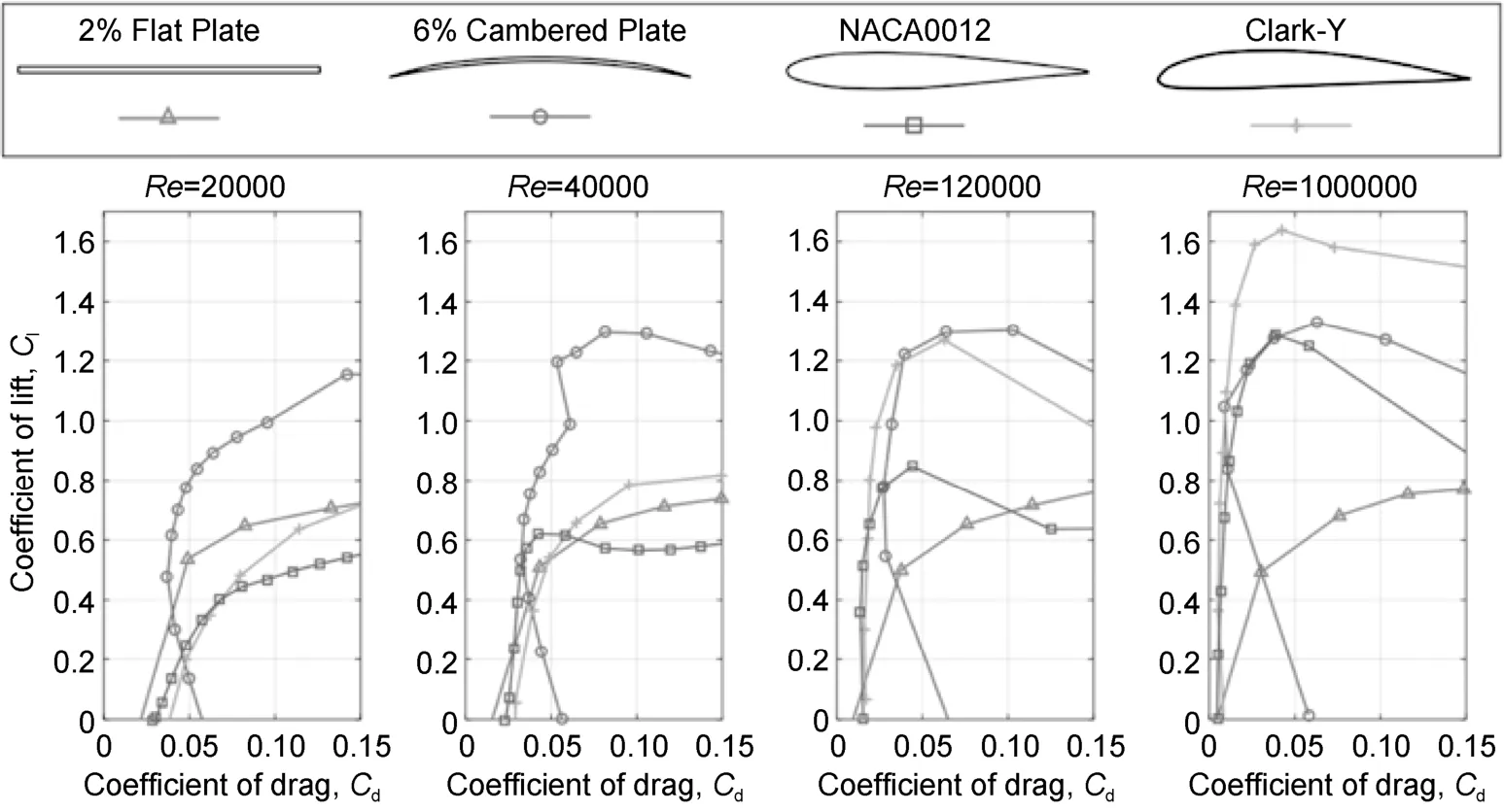
Figure 3 Effect of Reynolds number on multiple airfoils in terms of the drag polar (Winslow et al.,2018).
2.4.2 Materials
The material selected for fabrication of the propeller was Nylon 6 (Figure 4).It is a common commercially available material that has the following technical features and other characteristics that make it ideal for such purposes:
(1) Exceptional cut resistance;
(2) Self-lubricating,nonstick surface;
(3) Low coefficient of friction;
(4) Minimal wear and tear due to abrasive effects;
(5) High impact resistance;
(6) Resistance to chemicals;
(7) Minimal moisture absorption.
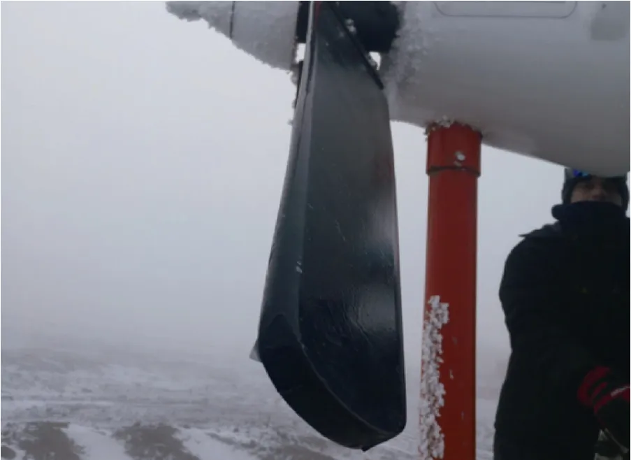
Figure 4 Flat plate blade made of Nylon 6 with angle of attack of 45°.
The meteorological data obtained at the Marambio scientific station indicated that the temperature could fall to-17 ℃ (Figure 2),which is another reason supporting the selection of Nylon 6 because the material has resistance to low temperatures.Its characteristics of a low coefficient of friction and a self-lubricating surface (U.S.Department of Energy,2020) mean that snow and ice cannot easily accumulate on or permeate the surface of the blade,making secondary measures such as anti-ice systems unnecessary.
2.4.3 Dimensions
The power coefficientCprepresents the main characteristic of a propeller,in combination with the dimension parameterλ.The latter establishes the relationship between the tangential speed of the blade tip and the actual wind speed (Figure 5):

whereRis propeller radius (m),ωis angular velocity (rad·s-1),andV1is wind speed (m·s-1).
Becauseλcombines the most important design variables,the behavior of any propeller can be fully defined by representing the power coefficientCpas a function of the speed ratioλ.Therefore,for the case of our propellor with parametersR= 2 m andV1= 80 km·h-1(22.2 m·s-1) (Figure 6),we findλ= 4.2.

Figure 5 Performance of windmill and wind turbine propellers (Bastianon,2008).

Figure 6 Aerodynamic performance (Cp) versus λ for propellors with different numbers of blades (Bastianon,2008).
It can be determined from Figure 5 that forλ= 4.2,the corresponding angular velocityωis 47 rad·s-1or 449 r·min-1.
Similarly,it can be determined from Figure 6 that for a three-bladed propellor,the corresponding power coefficientCpis approximately 0.55.The maximumCpvalues represent the maximum aerodynamic performance of the propeller.The higher the value ofλ,the more powerful the performance obtained.This is important when the electricity supply demands a high gearing ratio.
2.4.4 Gearbox
Having determined the velocity values,we designed the transmission gearbox using spur gear teeth made with Ultrapol,which is a common commercially available material in Colombia.It has the following technical characteristics that make it ideal for use for such purposes:
(1) Exceptional cut resistance;
(2) Self-lubricating,nonstick surface;
(3) Low coefficient of friction;
(4) Minimal wear and tear due to abrasive effects;
(5) High impact resistance.
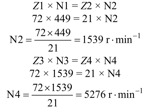
The gearbox comprised a set of four spur gears contained within a speed multiplier gearbox (Figure 7).The design parameters considered a minimum (maximum) input of 1000 (6000) r·min-1to the alternator:
A battery arrangement was incorporated for energy storage because the generated supply is correlated with the iterations of the wind.Thus,a minimum supply would be provided at times when the wind turbine did not operate within the ideal range of revolutions per minute of the alternator.
2.4.5 Generator

Figure 7 Schematic of the gearbox of the wind turbine.
Generally used in motor vehicles intended for different applications,the dimensions and functionality of generators tend to be determined based on different principles.The design of a generator is based largely around the requirements regarding the magnets or poles,the coil,and the material of the stator.Different configurations of the arrangement of the mechanical and electronic components will determine the energy supply.
The characteristics of the location of operation are important.For example,the three profiles of wind speed displayed in Figure 8 indicate that a wind turbine is likely to produce more energy in a coastal region owing to the absence of constructions such as the buildings that can affect wind speed over urban areas.
The alternator is at the heart of energy production by a wind turbine.In this case,its simplicity of design,ease of availability on the market,and reasonable cost were the primary considerations regarding selection.The components of the chosen alternator are shown in Figure A3.
It is important to highlight that the selected alternator is lightweight in comparison with many other assemblies that are developed for heavy duty cycles,and most of its component parts are made of aluminum.In a different part of the world,its use would not be practical owing to the strength of the wind required to break the inertia.Table 5 lists numeric values based on the relation between performance and torque,critical to alternator design.
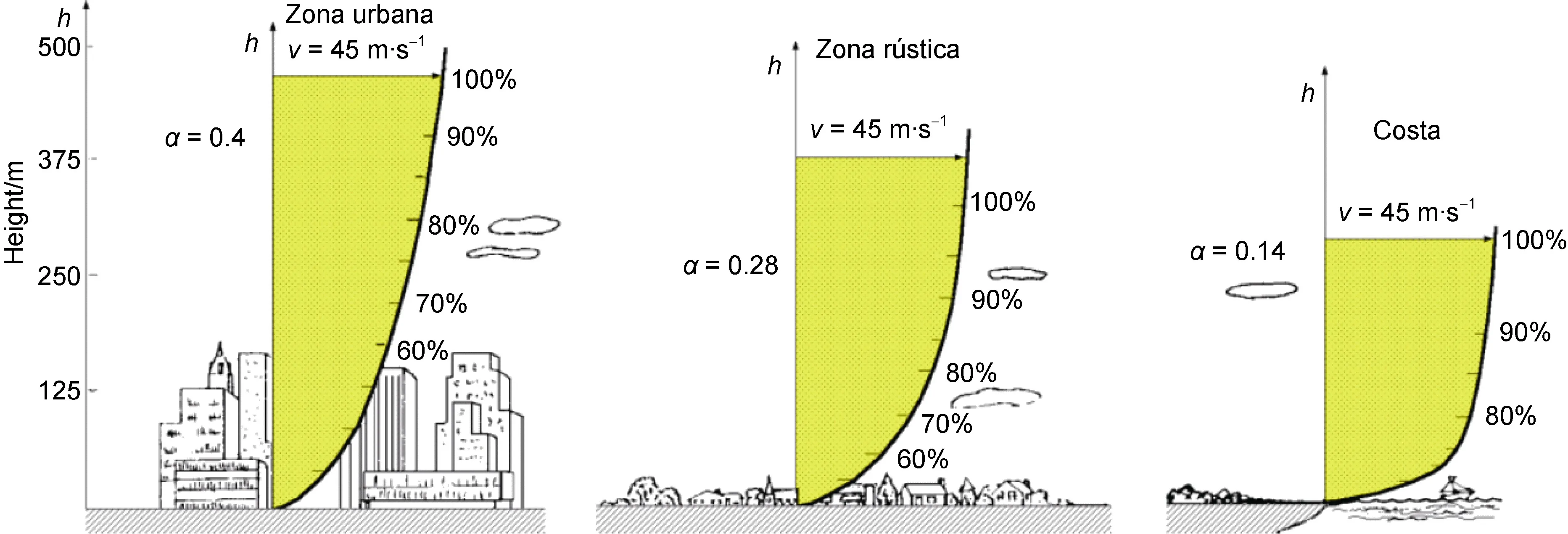
Figure 8 Wind profile characteristics (Armario,2012).
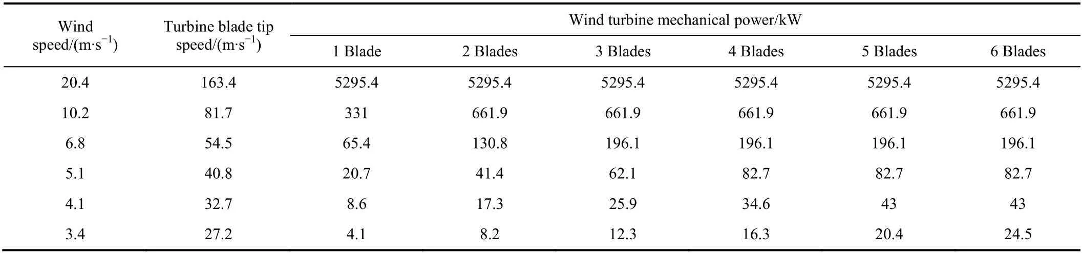
Table 5 Input parameters for alternator design based on the performance evaluation of horizontal axis wind turbine torque and mechanical power generation affected by the number of blades (Tan and Teow,2016)
The relationship shown in Figure 9 illustrates the mechanical power of a wind turbine with different numbers of blades versus wind speed.
Generator design involves many components that can affect the overall performance.The aim is to produce a consistent energy supply at competitive cost.
Increasingly,the properties of the materials involved in magnet design have risen in prominence because many alternative dope mixtures have been developed.For example,neodymium possesses optimal characteristics for implementation in future prototypes in various configurations that could allow greater output of power (Figure A4).
3 Second phase—installation at Marambio Station
The main objective of the second phase of the project was to transport the prototype wind turbine to Antarctica and install it at the Marambio Station (Figure 10).
The following specific objectives had been addressed previously and developed to help evaluate the in situ performance of the wind turbine:
(1) Tether anchors in the permafrost foundation;
(2) Collect indoor/outdoor temperature data;
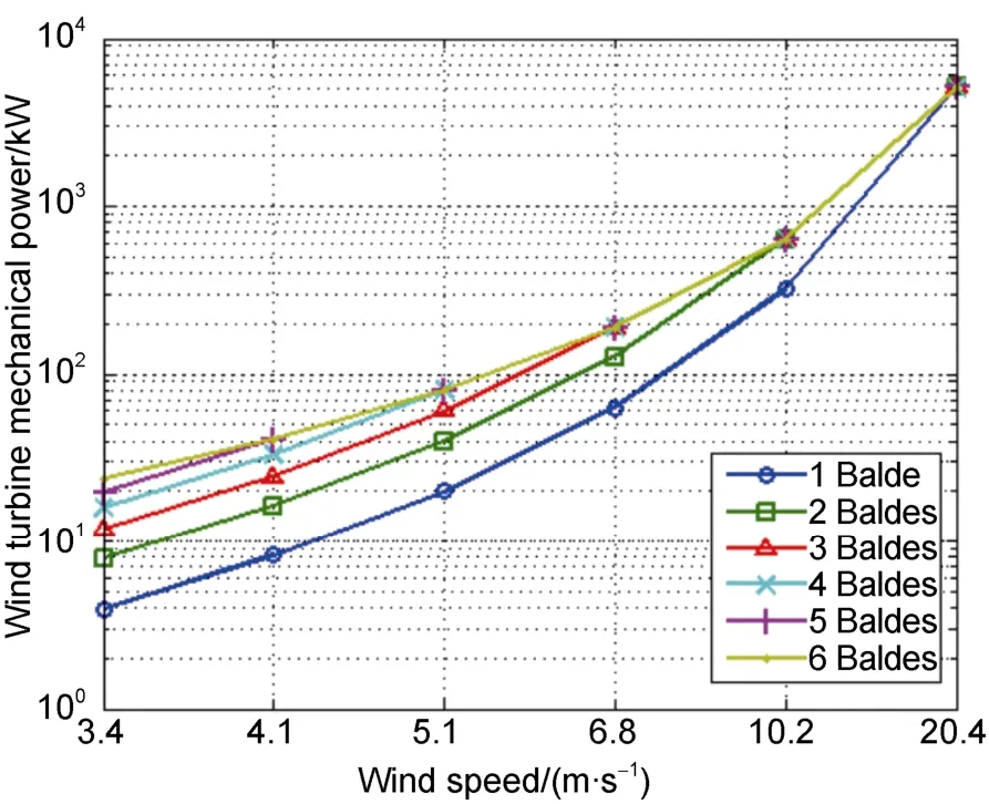
Figure 9 Mechanical power of a wind turbine with different numbers of blades versus wind speed (Tan and Teow,2016).

Figure 10 Installation of the wind turbine at Marambio Station in the Antarctic.
(3) Compute and monitor the energy supply generated by the prototype.
The logistics plan included shipment of Colombia’s first prototype wind turbine in a wooden crate (total weight:220 kg),with the assistance of the Command of Logistics in coordination with the Argentine Antarctic Logistics Command.The deployment from Bogotá,Colombia,to Marambio scientific station in Antarctica took 1 month.This was a crucial step with regard to fulfillment of the overarching objective of the project,and it represented animportant milestone of unknown complexity for the Colombian Air Force.
The work in the field was challenging and identifying a location with appropriate permafrost and wind conditions for installation of the prototype wind turbine was a time-consuming exercise that demanded considerable physical effort.
The installation work consisted of burying the main beam and providing ground tether anchorages to ensure safe support for the wind turbine assembly.A set of four anchorage points was required to hold the prototype securely given the severity of the winds.The soil composition would have made it difficult to drive the foundations because the permafrost type is compact and more formidable than concrete.However,fortunately,some attachment points created previously were found suitable for use.Nevertheless,the task of adapting and fitting the main base and securing and adjusting the cables took 2 weeks to complete.
At an extreme,temperatures can fall as low as-80 ℃,which could crystallize non-rubberized cables that undergo torsion forces (Suangga et al,2018).Furthermore,the cables could develop static that could induce electric shock.However,during the installation,there were no such problems with the cabling,as confirmed by conductivity tests performed during the initial days of operation of the wind turbine (Kletz,2009).
During the 2018 Antarctic campaign,the open fieldwork that was conducted regarding the assembly of the wind turbine comprised the following:
(1) On-site visual inspection of the main base foundation and the anchorages of the four tethers;
(2) Assessment of stress on the support and inspection for gaps in the anchorages;
(3) Examination of the hooks of the main docks to the beam in the permafrost;
(4) Examination of wear and tear of cables at support points;
(5) Installation of the generator by the working group;
(6) Assembly of mechanical components,i.e.,propellor,tail rudder,and others;
(7) Installation of electronic devices;
(8) Test operation of mechanical and electrical systems.
The work in the field was completed under exceptional conditions,i.e.,winds of 8–120 km·h-1and temperatures as low as-25 ℃.Owing to the severity of the Antarctic weather,the working party was split into a group rotation to facilitate completion of the tasks.The need for suitable clothing restricted mobility,which compromised the ability of those involved in manipulating components,tools,and accessories (Figure 11).
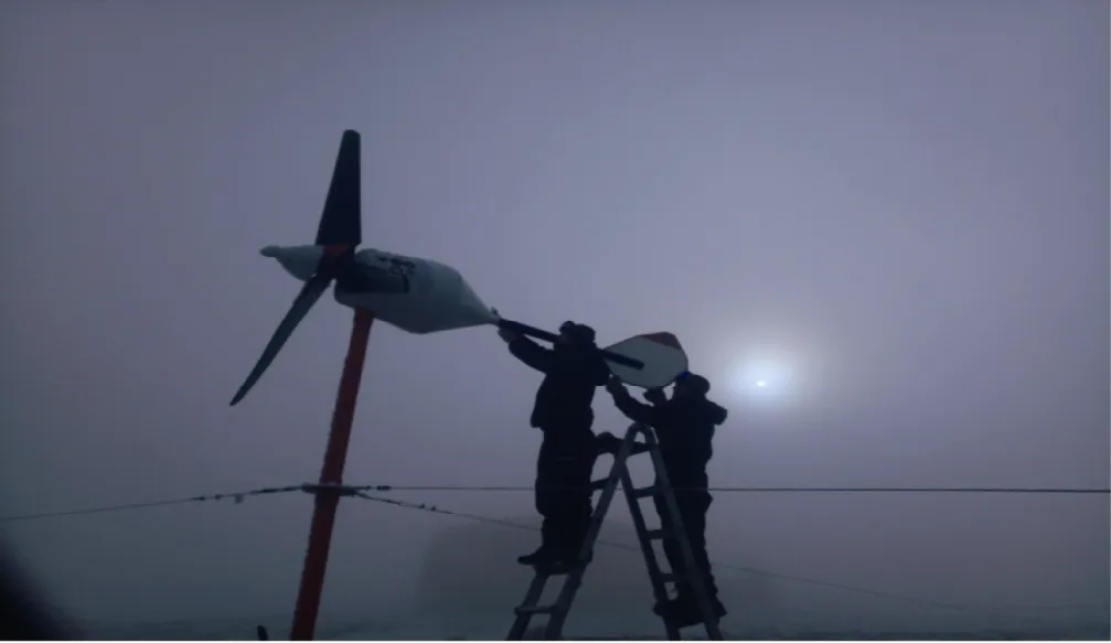
Figure 11 Final installation of the prototype Eolic turbine.
4 Third phase—prototype evaluation
After continuous operation for 2 years in Marambio Station,the performance of the prototype wind turbine was analyzed to provide feedback and knowledge for future developments.Nondestructive tests were performed on the three blades of the propeller after they were uncoupled,as shown in Figure 12.Visual inspection revealed severe granular corrosion on the fastening plates of each blade.
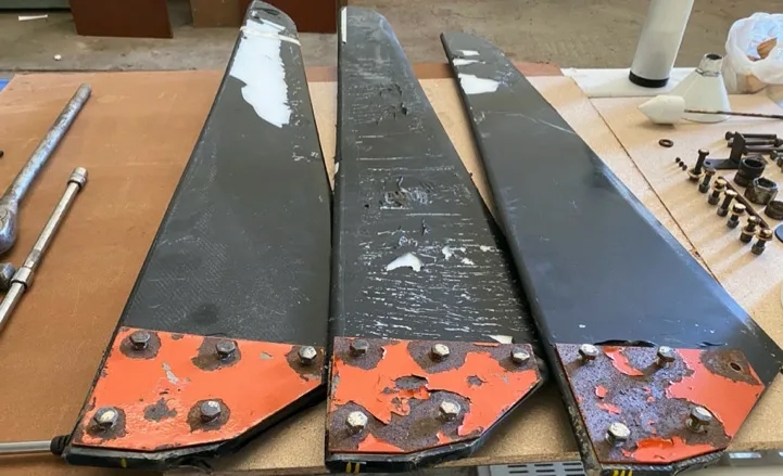
Figure 12 Visual inspection of the propellor blades.
In addition,using the magnetic particle technique,an ultrasound inspection was performed on the blades,with particular attention given to the leading edge,trailing edge,and blade-turbine joint (Figure 13).During the inspection process,no obvious indicators of major problems were found (i.e.,cracking,delamination,and loss of material due to erosion).Therefore,the performance of the blades during their 2 years of operation was considered satisfactory.
During visual and ultrasonic inspection of the blade supports,erosion and corrosion was evident over their entire surface,and loss of the anticorrosion coating owing to erosion was observed.However,no evidence of cracking was found,even around the holes that held the screws.
Similarly,ultrasonic inspection was performed on the 18 cast iron screws used to join the internal parts of the wind turbine to the plates of the blades (Figure 14).During the inspection,granular corrosion was evident in the heads of the screws and in the fastening part of the nut (i.e.,those areas exposed to the environment).

Figure 13 Ultrasonic inspection of the propeller blades.
Direct visual inspection using a 10× magnification lens was performed on the entire anchorage structure of the wind turbine after it was cleaned using SKC-S cleaner (Figure 15).During the inspection,granular corrosion was evident in 40% of the structure and loss of the anticorrosive coating (paint) was evident over 40% of the structure;however,no obvious indicators of major problems were found (i.e.,cracks,notches,and loss of material due to corrosion).
Inspection of the anchoring tube of the wind turbine was performed using the liquid penetration technique (Figure 16).The area to be inspected was first cleaned using SKC-S cleaner.Then,a penetrant (ZL-27A) was applied and allowed to penetrate for 30 min.Finally,a developer (SKD-S2) was applied and allowed a 15-min development time.
Owing to the high concentration of corrosion due to exfoliation resulting from loss of the anticorrosive coating,the base material had to be exposed by removing as much of the corrosion as possible using a motorized abrasive disc.Once the element to be inspected was prepared (Figure 17),a preliminary visual inspection was performed using a 10× magnification lens.
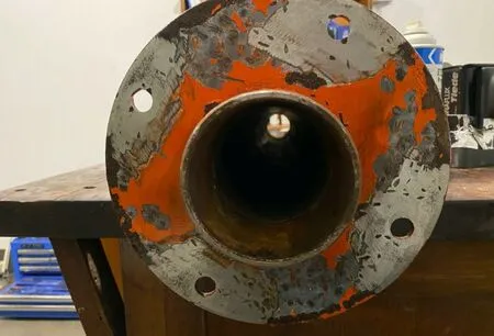
Figure 17 Support of the wind turbine tensor cable prepared for inspection.
The four clamping holes for the cable attachments at the base of the wind turbine were inspected using the magnetic particle technique,which revealed evident deformation (ovalization) and mechanical notching due to the tension exerted by the strong Antarctic winds (Figure 18).
The condition of the mechanical components contained within the nacelle of the wind turbine can be seen in Figure 19 and is discussed as follows.
(1) N3:Main gear with 72 teeth made of Teflon.Damaged during operation of the turbine,with broken teeth with 100% loss of material causing 90% loss of effectiveness;
(2) N4:Secondary gear with 21 teeth made of Teflon.Damaged during operation of the turbine,with broken teeth with 100% loss of material causing 80% loss of effectiveness;
(3) Hand Brake (Brake Gun):Used to arrest movement of the wind turbine,if required.Its performance was 80% effective following excessive wear of one of the two brake pads (inner);

Figure 18 Magnetic particle technique inspection of prototype.(Lozano,2015).
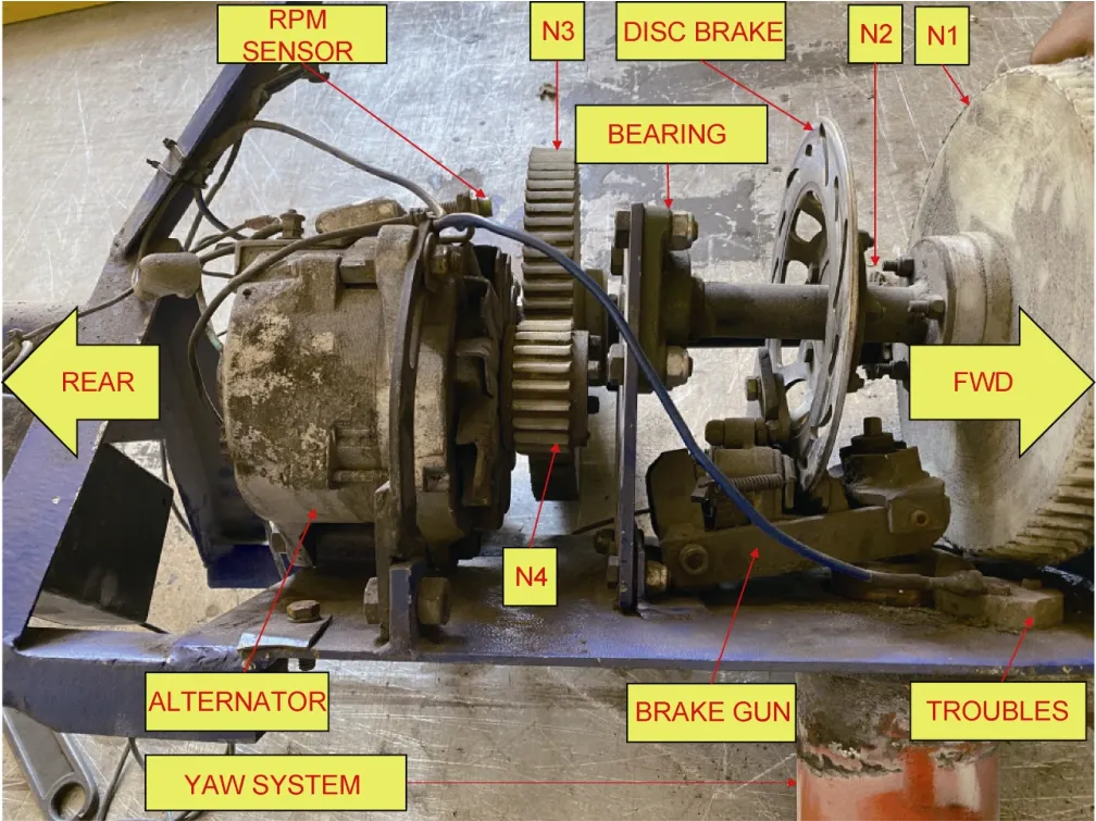
Figure 19 Mechanisms contained in the wind turbine nacelle.
(4) Disc Brake:Used to arrest movement of the wind turbine,if required.Its performance was 100% effective;
(5) Yaw System:Bearing mechanism by which the wind turbine can rotate with the direction of the wind.Its operational effectiveness was 50% owing to the corrosive environment,strong wind loading,and dust.Abrasion resulting from lack of preventive maintenance caused corrosion of the track and bearings,which resulted in loss of its ability to rotate;
(6) N2:Secondary gear with 72 teeth made of Teflon.Damaged during operation of the turbine,with broken teeth with 70% loss of material causing 70% loss of effectiveness;
(7) N1:Secondary gear with 21 teeth made of Teflon.Damaged during operation of the turbine,with broken teeth with 40% loss of material causing 50% loss of effectiveness;
(8) RPM Sensor:Electronic instrument that counts generator revolutions.Its performance was very poor (20% effectiveness) owing to humidity and dust;
(9) Alternator:Transforms mechanical movement into electrical energy.Its performance was reduced by 90%.
The directional bearing of the yaw system supports the combined weight of the propellers,hub,generator,and nacelle.The conditions of the Antarctic environment (i.e.,wind loading,dust,and other factors) contributed to abrasion of the metallic moving parts and corrosion of the track and bearings owing to lack of lubrication (preventive maintenance),which led to 100% reduction of its effectiveness (Figure 20).This damage caused misalignment of the main shaft of the wind turbine that resulted in abnormal wear and reduced power generation to 15% of its potential total capacity.
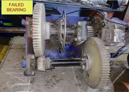
Figure 20 Wind turbine nacelle.
The damage caused by the failure of the bearing generated misalignment in the main axis of the tower,and this off-center movement caused imbalance that resulted in damage to the structure (Figure 21).It can be seen from the figure that the front support suffered loss of material,mechanical notching,and deformation.

Figure 21 Damage caused by failure of bearing.
Nondestructive visual inspection revealed three examples of cracking in the area of the foundation of the wind turbine.Furthermore,galvanic corrosion of the foundation screws resulted in loss of approximately 60% of the galvanized coating (Figure 22).
Direct visual inspection also revealed a crack of approximately 30 mm in length and loss of material in the main fastening plate,which was welded to a 5-mm-thick metal plate (Figure 23).
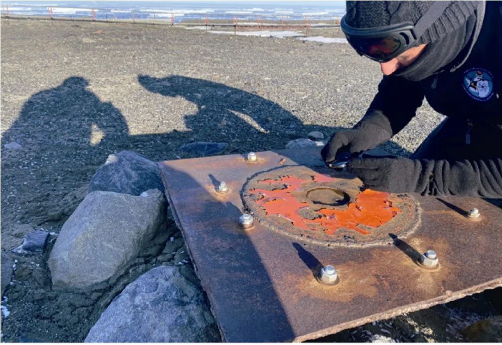
Figure 22 Visual inspection of the turbine base using a 10× magnification lens.

Figure 23 Cracks in the main fastening plate.
Assessment of the condition of the prototype wind turbine after continuous operation between March 2018 and the beginning of 2020 revealed the following:
(1) Failure of the main shaft bearing due to lack of lubrication and excessive vibration owing to the weight of the blade hub;
(2) Decomposition of the internal support of all mechanisms owing to high vibration;
(3) Deformation of gears due to mismatching;
(4) Disconnection of alternator gear due to high vibration and misalignment;
(5) Wear of all gears by erosion due to Antarctic dust;
(6) Corrosion of 90% of the wind turbine due to the caustic environment.
5 Conclusions
Although the prototype wind turbine could be improved,it is considered that it generally fulfilled the design requirements outstandingly.
Among the conclusions regarding the performance of the turbine,the most obvious improvements could be made in relation to both the ferrous materials and bearings to provide greater capability and sealing to maintain lubrication,and the overspeed system to protect against damage from the excessive wind.
An improved version of the prototype would be expected to provide remarkable performance in future implementation in Antarctica.It could provide greater generation capacity to support future campaigns conducted in compliance with environmental regulations such as the Tokyo Protocol and Paris Agreement,later ratified in the Annual Conference of Climate Change in Madrid 2019.Specifically,it could supply energy to a scientific base while meeting the Sustainable Development Goals of the Antarctic Treaty.
An upgraded turbine could supply energy to support up to four researchers in a temporary shelter during testing to gather further knowledge and to apply the lessons learned in this study with the objective of establishing a permanent Antarctic settlement.
AcknowledgmentsThanks to God,my family,my wife Pilar Barriga,and my children Maria Antonia and Cristobal.This work was supported financially by the Colombian Air Force (FAC).This work was undertaken in collaboration with the Comisión Colombiana del Oceano,Argentine Air Force (FAA),Joint Antarctic Command,and National Directorate of Antarctic Affairs.Special thanks are extended to Mr.Comodoro Enrique Oscar Videla (FAA),Mr.Comodoro Lucas Carol Lugones (FAA),Sergeant Major Gustavo Ferreyra (FAA),and Bedoya Garcia Gerardo (FAC).I would like to thank two reviewers (Jonathan Jimenez and an anonymous reviewer) and AE,Dr Joohan Lee for their valuable suggestions and comments.
Appendix A

Table A1 Properties of the U.S.Standard Atmosphere (Antarctic altitude = 3000 m) (Chegg Study,2015)

Table A2 Nylon 6 characteristics (ScienceDirect,2020)

Table A3 Ultrapol characteristics (made in Colombia) (COREL,2020)
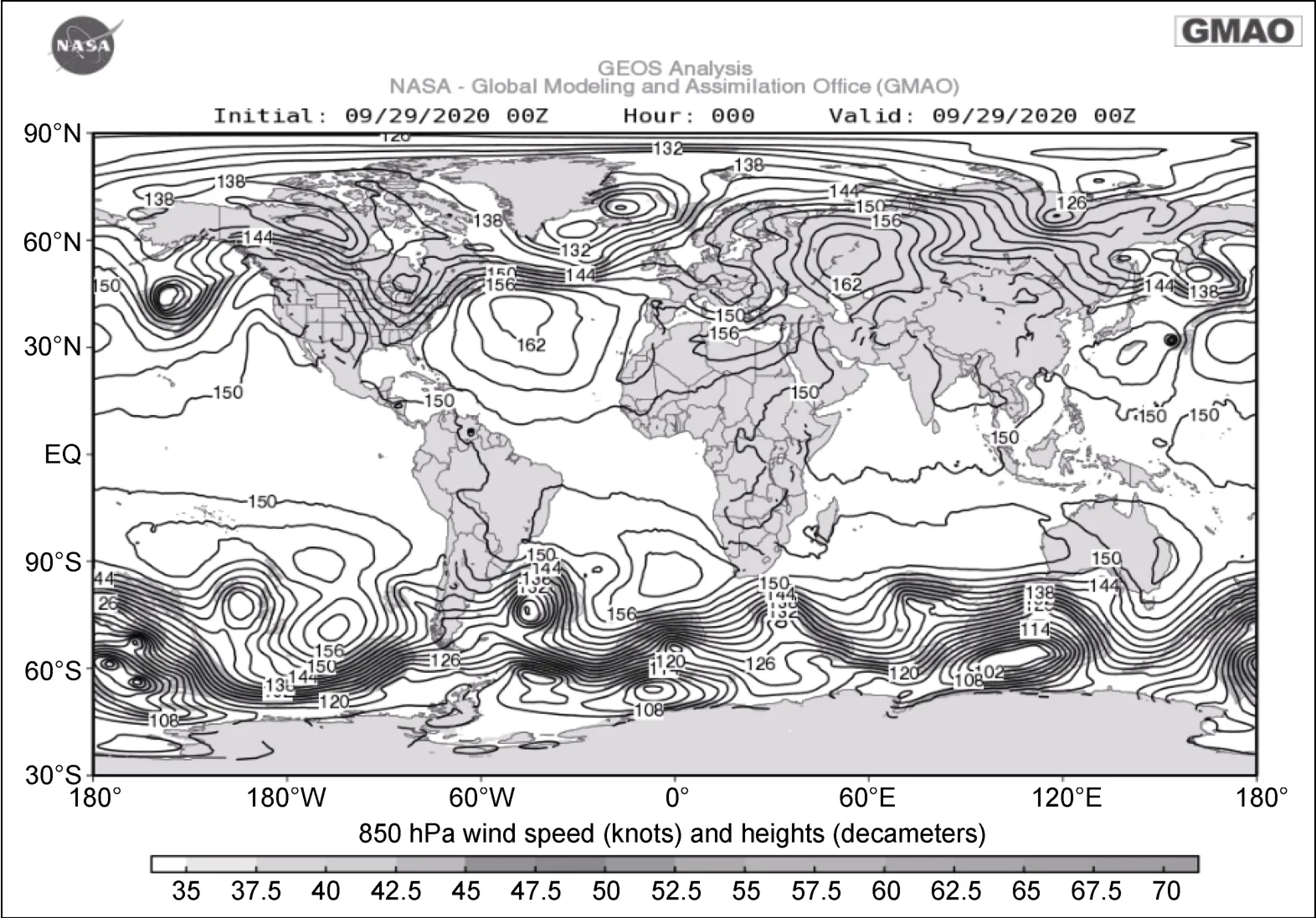
Figure A1 NASA global wind map (NASA,2020a).
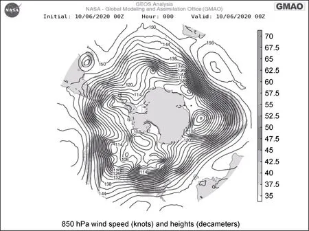
Figure A2 NASA Antarctic wind map (NASA,2020b).

Figure A3 Alternator parts (ComoFunciona,2020).

Figure A4 Location of permanent magnets:a,surface mounted magnets;b,inset rotor with surface magnets;c,surface magnets with pole shoes;d,embedded tangential magnets;e,embedded radial magnets;f,embedded inclined V-magnets with 1/cosine shaped air-gap;g,permanent magnet assisted synchronous reluctance motor with axially laminated construction (Kothari and Nagrath,2017).
杂志排行
Advances in Polar Science的其它文章
- Contents of Volume 31,2020
- Evaluation of the Polar Code in different environments and for different maritime activities in the two polar regions
- Large spread across AeroCom Phase II models in simulating black carbon in melting snow over Arctic sea ice
- Are Antarctic Specially Protected Areas safe from plastic pollution? a survey of plastic litter at Byers Peninsula,Livingston Island,Antarctica
- Air pollutants and greenhouse gases emission inventory for power plants in the Antarctic
- Approximating home ranges of humpback and fin whales in Drake Passage and Antarctica