Modal analysis of the torque converter in different prestress①
2020-04-10ZhangZeyu张泽宇HuiJizhuangShiZeSuoXuefengZhangXuhuiFanHongwei
Zhang Zeyu (张泽宇),Hui Jizhuang,Shi Ze,Suo Xuefeng,Zhang Xuhui,Fan Hongwei
(*Key Laboratory of Road Construction Technology and Equipment,Ministry of Education,Chang’an University,Xi’an 710064,P.R.China)(**Shaanxi Key Laboratory of Mine Electromechanical Equipment Intelligent Monitoring,Xi’an University of Science and Technology,Xi’an 710054,P.R.China)(***Research Center,Tibet Tianlu Co.Ltd,Lhasa 850000,P.R.China)
Abstract
Key words:hydraulic torque converter,modal analysis,prestress,finite element analysis
0 Introduction
With the development of vehicles in the trend of high power,high speed and high reliability,the vibration and noise generated in the structure under dynamic load are increasingly prominent[1-6].The torque converters have been extensively used in various types of vehicles.Exploring their mechanical properties and dynamic performance could be helpful to avoid the deterioration of dynamic performance caused by resonance,the reduction of service life,and the destruction of existing structures,etc.[5-12]
The centrifugal load is large when the torque converter is in high-speed rotation[7-9].The structural stiffness of the torque converter impeller could be altered by the resulting rotational prestress,which affects the natural frequency of the structure[12-18].However,the mode of the torque converter is difficult to be measured by experiment,so it is necessary to perform a computational modal analysis.Yu et al.[19]analyzed the main shaft of the ultra-high-speed grinding machine tool and obtained its natural frequencies and modes.The critical speed of the spindle was obtained by the graphical method under the bearing support stiffness of the machine at various speeds.The results showed that the natural frequency of the main shaft changed with the increase of the rotational speed[19].Wu et al.[15]carried out model vibration shape analysis on the pump impeller and guide wheel of the torque converter based on the finite element dynamic characteristic equation.The variation of the frequency of the pump wheel was studied by changing the rotation speed of the pump wheel and theoretical basis was provided for the structural optimization[15].Minette et al.[20]conducted a dynamic behavior study on the natural frequency and damping parameters of the electric submersible pump in the test well.The experimental modal study was carried out using the excitation generated by the hammer at one point,and the scope of frequency that should be avoided in pump operating was obtained[20].Putz et al.[21]studied the dynamic behavior of machine tools to improve the quality and productivity of workpieces.Considering time invariance and the relevant effects of cutting and operation,the processing procedure was evaluated by power spectral density and modal analysis.
In summary,the vibration mode analysis has been studied for machine tools and electric well pumps,which provides the theoretical basis for modal analysis.However,there are few work for turbines and pump wheels of the torque converters on multi-speed and sub-operating conditions in the case of prestress.In this paper,the modal simulation of a 215 mm hydraulic torque converter is carried out based on finite element analysis.Its natural frequency and vibration mode are calculated,and the structural natural frequency variation at different speeds is analyzed.
1 Computational modal analysis method and solution process
1.1 Computational modal analysis of torque converter
The finite element method could be used to discretize the vibration structure in computational modal analysis.The physical coordinates could be linearly transformed to solve the eigenvalues and eigenvectors of the system by establishing a mathematical model of the system eigenvalue problem and using the weighted orthogonality of the modal vector and the transformation matrix composed of each order modal vectors.The solved eigenvalues and eigenvectors are the natural frequencies and natural mode vectors of the system.The responses of any excitation could be linearly combined with this method.Since the coefficients of the low-order modes are weighted more than higher-order modes,only the first few modes are selected for superposition.The three basic assumptions of structural modal analysis are:1) the system being identified is linear;2) the system is stationary;3) the system is observable[22-24].
The vibration structure of the torque converter is discretized into multi-freedom system,and the dynamic model is described bynindependent physical coordinates.In the linear range,the free vibration response in the physical coordinate system is a linear superposition ofnmain vibrations,each of which is a simple harmonic vibration or attenuated vibration.Therefore,the torque converter studied in this paper is ann-degree of real-mode system with viscous damping.
Modal equation:

(1)
Since the modality is an intrinsic property of the system structure and is independent of the external load,it is not necessary to set the external boundary condition when performing the modal analysis,that is,the total load vectorf(t)=0.Therefore,in the case of free vibration,the equivalent form of Eq.(1) is:

(2)
whereCcould be diagonalized by orthogonality:
C=αM=βK
(3)
whereαandβare the constant of external and internal damping of the system.
One of the special solution of Eq.(2) has the form :
x=φeλt
(4)
Substituting Eq.(4) into Eq.(2):
(λ2M+λC+K)φ=0
(5)
The characteristic equation is:
|λ2M+λC+K|=0
(6)
This is a 2n-order real-coefficient algebraic equation ofλ.Let it have no multiple roots,and the divergent eigenvalues of 2nconjugate pairs could be solved.
(7)
And:
(i=1,2,…,n) (8)
where the real part ofλirepresents the attenuation coefficient,and the imaginary partωdirepresents the natural frequency of thei-th order damping.The modulus ofλiis equal to the undamped natural frequencyω0i.
There arenindependent feature vectors after the calculation,andnfeature vectors could be arranged in columns to obtainn-by-n-order eigenvectors,that is,modal matricesφ.
The eigenvectorφior the modal matrixφis orthogonal to theM,C,andK,wherein the modal mass matrix,the viscous proportional damping matrix,the modal stiffness matrix,and the spectral matrix are:
(9)
The free response in the real mode coordinate system is:
(10)
And:
(11)
The free response in the physical coordinate system is:

(12)
And:Di=φiYi(i=1,2,…,n)
Ifxivibrates at a damped natural frequencyωdiin the system,the vibration law is:
xi=Die-σitsin(ωdit+θi)
(13)
This is the main vibration of the viscous proportional damping system,and the vibration form isDi∞φi.Therefore,the main vibration modeφireflects the shape of the main vibration of the system.Each ofxiis the free response of each element to each physical coordinate under thei-th order main vibration.
xki=Dkie-σitsin(ωdit+θi)
=φkiYie-σitsin(ωdit+θi)
(k=1,2,…,n) (14)
It could be seen that the initial phase of each physical coordinate for freely attenuating vibration is the same as that in thei-th order main vibration.
The frequency response function matrix is:
(K-ω2M+jωC)X=F
(15)
The modal expansion of the frequency response function is as follows:
H(ω)=(K-ω2M+jωC)-1
(16)
The impulse response function is expressed as
(17)
1.2 Computational mode solution process of the torque converter
The prestress of the torque converter is mainly composed of the tensile prestress of the shaft end constraint and the radial tensile stress generated by the centrifugal load of the impeller (pump and turbine) at high-speed rotation.The equilibrium position of the prestress load could be changed in the event of impeller vibration.It is generally considered that the nonlinearity of the prestress stiffness matrix is inconspicuousness near the rotational balance position of the impeller and the position where the deformation is small,and the influence of the deformation on the equilibrium equation is not significant too.Therefore,the process of solving the equilibrium position of the impeller could be simplified as follows:The axial tensile stress and centrifugal tensile stress under static stress conditions act on the discrete finite elements of the impeller respectively.
Therefore,the models of torque converter could be analyzed and solved by ANSYS software which is based on the principle of computational modal analysis.The main process is shown in Fig.1.

Fig.1 Modal process of the torque converter
2 Modal simulation of torque converter based on ANSYS
2.1 Computational model
A 215mm torque converter is taken as the research object in this paper,and the basic parameters of the blades are shown in Table 1.

Table 1 Parameters of a 215 mm hydraulic torque converter
The pump wheel driven by the engine provides the power to the hydraulic system,which drives the turbine,while the guide wheel is static.Therefore,the models of the turbine and the pump wheel have been built in this paper.
The model of the torque converter is solved inversely by a three-coordinate measuring instrument,and the wheel’s models are built by a single-blade rotating array and imported into ANSYS.The processed torque converter geometry models are shown in Fig.2.
2.2 Meshing
The shell and blade of the torque converter impeller are unequal thickness structures with many curved surfaces and large variations.Therefore,meshing in ANSYS is used for mesh generation.The meshed results of the pump wheel and the turbine are shown in Fig.3.
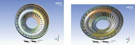
Fig.2 Models of the impeller and turbine

Fig.3 Meshing of the impeller and turbine
2.3 Modal calculation
The torque converter is in a high-speed rotating condition in the transmission system,and the simple static analysis could not fully reflect its actual state.The hydraulic transmission oil acts as the prestress under the action of centrifugal force,and the centrifugal load increases with the rotational speed.The vibration frequency of the hydraulic torque converter could be affected by the change of the prestress.Therefore,the influence of the rotational speed should be taken into account in the modal analysis of the torque converter,and the calculation under the condition of non-prestress and prestress should be performed separately.
In this work,the modal analysis is performed using the unconstrained free boundary and the Block Lanczos extraction method without considering the prestress generated by the rotation.The speed ranging from 100 rpm to 4 500 rpm is set to analyze the modal performance of the impeller under centrifugal load.
Since the frequency of the load applied by the torque converter is generally low,the vibration of the structure is dominated by the low-order mode,and the influence of the higher-order mode is small.Therefore,the first 4 modes are selected for analysis.
3 Modal analysis of torque converter
The modal analysis of the impeller of the torque converter was carried out without prestress in this paper,and then the prestressed modal calculation was taken to analyze the influence of the centrifugal load generated by the hydraulic transmission oil on the fundamental frequency of the impeller at different rotational speeds.
3.1 Modal analysis of pump impeller without prestress
The modal frequency would be 0 Hz regardless of the prestress when the speed is 0 rpm.Therefore,the rotational speed is selected as 100 rpm.At this time,the first 4 modal frequency distribution of the pump wheel is as shown in Fig.4.
It could be seen from Fig.4 that the 1st-order mode (f=774.45 Hz) and the 2nd-order mode (f=774.67 Hz) cause the pump wheel swing,and the maximum deformation appears on both sides of the outer edge of the impeller.The maximum deformation of the 3rd-order mode (f=1026.5 Hz) and the 4th-order mode (f=1026.8 Hz) occurs at the 4 edges of the outer edge of the impeller,and the deformation of the center of the pump wheel is the smallest.The results are shown in Table 2.

Fig.4 Modals of the impeller of the first 4 modes

Table 2 Modal frequency distribution of pump wheel
3.2 Modal analysis of pump impeller under prestress
The influence of the rotational speed on the fundamental frequency of the structural vibration is studied by taking the different rotational speeds of the pump wheel as independent variables.Take the partial speed from 100 rpm to 4 500 rpm as the design point and fit the relationship between the variables,as shown in Fig.5.
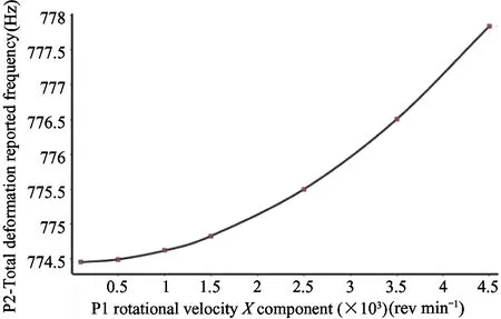
Fig.5 Variation trend of the impeller’s fundamental frequency at the different speed
It could be seen from Fig.5 that the fundamental frequency of the pump wheel increases from 774.45 Hz (100 rpm) to 777.84 Hz (4 500 rpm),which increases about 0.43% with the influence of the prestress caused by the centrifugal load.At the same time,the influence of the prestress generated by the centrifugal load on the fundamental frequency is more prominent with the increase of speed,as shown in Table 3.

Table 3 Modal frequency distribution of turbine
3.3 Modal analysis of the turbine without prestress
The turbine is connected to the output shaft of the torque converter,and the change in its rotational speed is also important for the dynamic analysis of the vehicle transmission system when the vehicle is in operation.The prestress modal analysis method is used to calculate the first 4 modes of the turbine at the speed of 100 rpm,as shown in Fig.6.
It can be seen from Fig.6 that the maximum deformation of the 1st-order mode (f=381.86 Hz) and the 2nd-order mode (f=382.18 Hz) appears on both sides of the outer edge,the 3rd-order mode (f=663.18 Hz) could appear in the outer ring of the turbine,the maximum deformation of the 4th-order mode (f=1185.3 Hz) occurs at 4 locations where the outer edges are symmetrical.
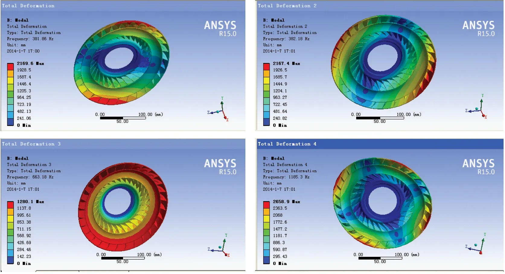
Fig.6 Modals of the turbine of the first 4 modes
3.4 Modal analysis of turbine under prestress
The turbine speed was set ranging from 100 rpm to 4 500 rpm to study the effect of the rotational speed on the fundamental frequency of the structural vibration.The variation trend of structure vibration frenquency with turbine speed is shown in Fig.7.
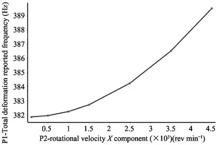
Fig.7 Variation trend of the turbine’s fundamental frequency at different speed
The minimum fundamental vibration fundamental frequency is 371.6 Hz (100 rpm),and the maximum vibration fundamental frequency is 389.54 (4 500 rpm),which increases about 4.82%.The trend of the turbine is the same as that of the pump wheel,but the effect on the fundamental frequency of the turbine is more obvious with the change of the speed.
3.5 Suggestions for improvement
From the modal vibration mode analysis,the vibration shape and weak parts of the impeller structure could be determined,which provides a basis for structural improvement.It could be seen from the first 4-order mode of the pump impeller of Fig.4 and the first 4-order mode of the turbine of Fig.6 that the deformation of the outer side of the impeller housing is large,indicating that the rigidity of these portions is small.It could be improved by the following aspects.
1) Appropriately adjust the thickness of the parts of the impeller,increase the thickness of the outer edge of the shell and the blade,and distribute the stiffness more reasonably.
2) Appropriately increase the length of the pump wheel,the turbine blade and the outer edge of the housing to increase the rigidity of the impeller.
3) Use hinge or welding to connect the blade to the casing to improve its modal condition.
4 Conclusion
1) The first 4 modal frequency of the pump wheel is between 770 Hz and 1 030 Hz,and the turbine is between 380 Hz and 1 200 Hz.In order to ensure the safe and stable operation of the vehicle and avoid the noise and deformation caused by resonance,it is necessary to avoid this frequency band when designing the working speed.
2) Through the analysis of the 4th-order modes of the pump wheel and the turbine,it is found that the deformation of the outer side of the impeller casing is large,and the modal state needs to be improved by thickening and improving the process.
3) When the speed ranges from 100 rpm to 4 500 rpm,the torque converter is affected by the prestress caused by the centrifugal load,which causes the fundamental frequency of the pump wheel and the turbine increased by 0.43% and 4.82% respectively.On one hand,it shows that the fundamental frequency of structural vibration increases with the increase of prestress.On the other hand,the difference between the modal frequency and natural frequency is very small.The modal state in the static state could be used instead of the modal under motion.
4) The modal analysis of the torque converter under prestress conditions was carried out in this paper.Due to the limitation of the experimental conditions,it is difficult to measure the modal condition of the high-speed rotating system by experiment.According to the conclusion of this paper,experimental analysis of its experimental modal conditions without prestress conditions would be the focus of the next work.
杂志排行
High Technology Letters的其它文章
- End-to-end verifiable electronic voting scheme of blockchain based on random linear block code①
- Improved Fx-VSSLMS algorithm for active vibration control of smart cantilever beam①
- Structural form selection of the high-rise building with the improved BP neural network①
- Decision-feedback subset aided multiple-symbol differential detection①
- A new diagnosis strategy under the PMC model and applications①
