Frequency sensitivity of the passive third harmonic superconducting cavity for SSRF
2020-03-19XiaoYunPuHongTaoHouYanWangZhengLiJingShiYuBinZhaoJianFeiLiu
Xiao-Yun Pu· Hong-Tao Hou· Yan Wang · Zheng Li ·Jing Shi · Yu-Bin Zhao· Jian-Fei Liu
Abstract A 1.5 GHz passive third harmonic superconducting cavity was proposed to improve the beam quality and lifetime in the Shanghai Synchrotron Radiation Facility Phase-II beamline project. Lifetime improvement highly depends on the resonant frequency of the passive third harmonic superconducting cavity. It is important that the operating frequency of the cavity is within the design range and the cavity has reasonable mechanical stability.A simulation method for the multiphysics coupled analysis has been developed based on the ANSYS code. Multiphysics coupled simulations have been performed under different conditions, such as etching, evacuation, cooling,and preloading. Analyses of mechanical modes and structural stress have been executed. A possible stiffening ring method for the two-cell superconducting niobium cavity has been investigated. In this paper, we present a multiphysics coupled analysis of the third harmonic cavity using a finite element analysis code. The results of the analysis show that a reliable frequency for the cavity after electron beam welding is 1498.033 MHz, and the corresponding frequency of the pre-tuning goal is 1496.163 MHz. A naked cavity is a reasonable option based on structural stress and mechanical modal analyses. A frequency range of ± 500 kHz and limiting tolerable displacement of ±0.35 mm are proposed for the design of the frequency tuner.
Keywords Superconducting cavity · Passive harmonic cavity · Frequency detuning · Frequency tuner ·
1 Introduction
The Shanghai Synchrotron Ra diation Facility (SSRF) is a medium-energy third-generation light source with a 3.5 GeV low-emitting storage ring [1, 2]. It is now well established from a variety of studies that the beam lifetime in a medium-energy third-generation light source mainly depends on the Touschek lifetime, which is limited by the intrabeam scattering effect [3–5]. Based on this fact, the harmonic radio frequency (RF) system has been used in some storage rings,such as SLS and ELETTRA,exhibiting an improvement in the beam lifetime of a factor of 2–4 without affecting the emittance [4]. One attractive option for improving the beam lifetime is to lengthen the bunches using a passive third harmonic superconducting cavity without an external high-power source, as the voltage in a passive cavity is generated by the beam [6].
The passive third harmonic superconducting cavity operating at the frequency of 1.5 GHz has been proposed to increase the beam lifetime by an approximate factor of 3 and compensate for the nonlinear distortions in the longitudinal phase space due to the RF curvature of the 500 MHz cavity accelerating voltage[7–9].This cavity is a new design,based on the shape of the TESLA middle cell,and is expected to provide an accelerating field of approximately 9 MV/m [10]. The main electromagnetic parameters of the third harmonic superconducting cavity are listed in Table 1.The higher-order mode damper of the third harmonic superconducting cavity is similar to the fluted beam tube of the SSRF 500 MHz cavity.
For the SSRF, improvement in the lifetime mainly depends on the voltage of the passive third harmonic superconducting cavity, which changes with the resonant frequency [6]. Recently, developments in the passive third harmonic superconducting cavity have increased the requirements for frequency sensitivity and mechanical stability [11, 12]. The frequency of the cavity changes during product processing, such as fabrication, etching,assembly, evacuation, cooling, and preloading. Furthermore, the typical intrinsic quality factors of superconducting cavities range from 109to 1010, which are many orders of magnitude higher than those of normal conducting cavities.Therefore,the power losses of the cavities are smaller,particularly in the case of the cavities operating at 2 K, as explained by Bardeen–Cooper–Schrieffer theory[13]. Because of its small bandwidth and thin shell structure, the high-frequency superconducting cavity is extremely sensitive to mechanical deformations induced by external sources, such as beam current variations, Lorentz force detuning, helium pressure fluctuation, and the microphonic effect [14–16]. On this basis, the main challenges are to ensure that the operating frequency of the cavity is in the design range and to maintain stability in the cavity’s mechanical design.
The design and fabrication of high-Q superconducting cavities with very precise operating frequencies and tolerances (for tuner design) are of general interest in the particle accelerator community. In this study, we present a general multiphysics approach to studying superconducting cavity performance. While the third harmonic cavity for the SSRF is the primarily focus, this approach may be useful for any laboratory designing a superconducting cavity with interest in its performance quality, resonancefrequency shift range, and resonance tuner design. The frequency operation scheme of the third harmonic cavity has been investigated,and the target frequency of the third harmonic cavity has been confirmed. Furthermore, the frequency pre-tuning goal of the cavity in the production process has been given.The mechanical resonant mode and structural stress analyses are performed to determine whether stiffening rings between the two cells of the harmonic cavity should be adopted. The tuner design parameters of the frequency range and limiting tolerable displacement are presented.
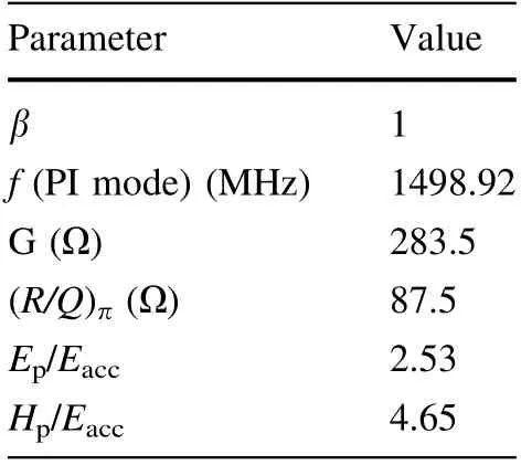
Table 1 Main electromagnetic parameters of the third harmonic cavity
2 Target frequency of operation
Maximum bunch lengthening is achieved when the third harmonic beam-induced voltage is approximately one-third of the overall voltage produced by the main RF system[8].When the cavity detuning is large in comparison with the resonance bandwidth, the voltage generated in the cavity can be defined as in Eq. (1) [3]:
where fhrfand Δf =fhrf-3frfare the harmonic cavity resonant frequency and detuning, respectively, Ibis the beam current, R is the shunt impedance, and Q is the quality factor. The voltage of a passive harmonic cavity is generated by the beam.When the SSRF operates in the topup operation mode,the resonant frequency of the main RF system frf=498.692 MHz and beam current Ib=300 mA.For the third harmonic cavity, R/Q=87.5 Ω. It is known from Eq. (1) that a detuning frequency Δf=22 kHz is necessary to gain a harmonic cavity voltage V of 1.8 MV.Since ±1% stability of the harmonic cavity voltage is required, a frequency fluctuation below 220 Hz is needed.Furthermore,the tuning accuracy of the tuner must be oneorder higher, and the selection is 10 Hz.
The frequency of the cavity parking mode was used to minimize the induced voltage that could perturb the electron beam stability [17]. The cold parking fcpfrequency of the cavity is chosen based on Eq. (2):
where the frevis the revolution frequency of the storage ring. For the SSRF, frevis 693.964 kHz, and fcpis set to 326.982 kHz above the 3frflevel,which is 1499.076 MHz.In this cold parking mode, the third harmonic cavity is under a superconducting state, and the induced voltage is negligible. Therefore, a maximum tuning range of ± 500 kHz is needed to park the cavities between the two harmonics of the machine. The operation schematic diagram of the passive third harmonic superconducting cavity is shown in Fig. 1.The warm parking mode is decided based on simulation results in the following section to allow the operation of the SSRF in case of a breakdown of the 2 K cryogenic system for the passive third harmonic superconducting cavity.
3 Multiphysics coupled simulation
According to Maxwell’s equation, the resonant frequency of a vacuum cavity is linked to its geometrical shape and dimension. The frequency shift Δf of a cavity perturbation can be approximated by Eq. (3):
The multiphysics coupled simulation process consists of four key steps. First, the resonant frequency is calculated by high-frequency eigenmode analysis using the vacuum mesh model.Second,structural analysis is performed using the structural mesh model with different loads and boundary conditions. Third, to reflect the resulting geometry change, the mesh for the FEA model is updated using ANSYS code UPCOOD. Finally, a high-frequency eigenmode analysis is conducted with the updated vacuum mesh model. Thus, the corresponding resonant frequency shift was determined for the two models.It is worth noting that,in the analysis model, the nodal displacements located at the interfaces can be correspondingly transferred from the cavity structural mesh model to the vacuum mesh model because the outer side of the vacuum volumes and inner side of the cavity volumes share common faces. Furthermore,a mesh independent analysis was performed,and the results showed that two million mesh numbers are necessary for this simulation.
The third harmonic cavity is designed to operate at a low temperature of 2 K under vacuum conditions.The resonant frequency of the third harmonic cavity can change owing to manufacturing, surface polishing treatment, cavity evacuation, cooling, and preloading. The narrow bandwidth makes the superconducting cavity more sensitive to mechanical vibration due to helium pressure fluctuation or the microphonic effect.
4 Results
4.1 Etching sensitivity
The RF performance of a superconducting cavity can be improved by surface treatment, which removes the mechanically damaged inner surface layer as well as any evaporated niobium scale deposited on the surface duringwelding. Etching of the cavity is prepared in two steps,namely, bulk buffer chemical polishing (BCP) and final BCP. In the simulation, we assume that the surface deformation of the third harmonic superconducting cavity is uniform during the etching process. The results of the simulation are presented in Fig. 3. The results show that the resonant frequency of the 1.5 GHz two-cell cavity decreases with increase in the polishing thickness and the etching sensitivity is 11 kHz/μm. In this case, the resonance frequency increases by 1.1 MHz when the polishing thickness is 100 um.
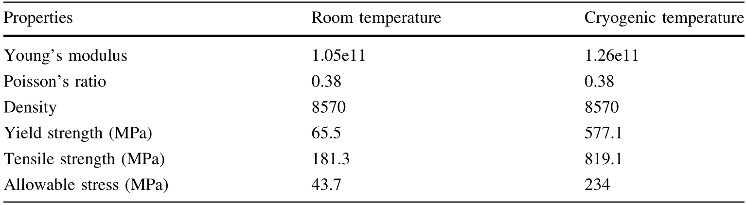
Table 2 Mechanical properties of high residual resistance ratio niobium used in the simulations
4.2 Tuning sensitivity
The shift of the cavity resonant frequency versus cavity longitudinal displacement is defined as the tuning sensitivity for the passive third harmonic superconducting cavity. As mentioned before, the multiphysics coupled simulation model is used to calculate the tuning sensitivity of the third harmonic cavity. In this simulation, the tuning force is applied to the one-beam pipe port, while the other side remained fixed.The tuning range R and tuning force F are related to the cavity stiffness K and tuning sensitivity S by Eq. (4):
Tuning sensitivity S is 1.52 MHz/mm for the axial displacement on the beam pipe. Cavity stiffness K is calculated at different temperature conditions. The results show that K is 13.5 kN/mm for the one-beam pipe tuning force at room temperature(RT)approximately 300 K,and 16.2 kN/mm for the one-beam pipe tuning force at the cold temperature (CT). The peak deformation and peak von Mises stress vary linearly with the tuning force.The tuning range and cavity stiffness are designed to meet the operation request. To achieve a coarse tuning range of 500 kHz, a tuning of 330 μm is needed. Consequently, a force of at least 4.5 kN is needed from the tuner to obtain an operating tuning range of 500 kHz,considering the stiffness of other supports. In addition, the results also show that the cavity can be tuned 0.7 mm at RT and 1 atm pressure under the elastic range.
The peak deformation and peak von Mises stress caused by tuning 1 mm before and after adding the stiffener are compared. The peak deformation and peak von Mises stress under a 1 mm displacement are shown in Fig. 4. On the one hand, the maximum stress in the naked cavity is between the two cells, whereas the stress in the middle position decreases after the stiffening rings are added. On the other hand, it was found that the cell deformation after tuning was relatively uniform for the naked cavity,whereas the deformation after tuning between the right and left side of a cell differed for the stiffened cavity,which may reduce the field flatness of the cavity.
4.3 Pressure sensitivity
The frequency change due to the fluctuation in the helium pressure is calculated using the mechanical analysis solver and RF model analysis solver. The pressure sensitivity was studied with three boundary constraints,including a two sides fully fixed condition,a condition with one side fixed and one side free, and a two sides free condition. The pressure load was applied to the outer shell surfaces of the cavity.The outer tank was not considered in this model as the geometry change of the outer tank has little effect on the cavity body.The results are summarized in Table 3. The real boundary condition of the cavityinstalled in the cryomodule is somewhere between the fixed and the free case;thus,the helium pressure sensitivity factor df/dp is between + 1.9 Hz/mbar and - 15.3 Hz/mbar.A support structure for the harmonic cavity was also considered in the mechanical analyses. The helium pressure fluctuation analysis was conducted on the cavity with differential stiffening rings as shown in Fig. 5. The results demonstrate that, after the reinforcement is added, the coefficient of the fixed port increases first and then decreases with the reinforcement position, but the overall change is not significant. The absolute value of the free helium pressure fluctuation coefficient also increases at one end and then decreases. The results show that the effect of the helium pressure fluctuation on the frequency is reduced when the stiffener is in a suitable position. Based on previous experience, the helium pressure fluctuation of a 2 K cryogenic system is less than 0.3 mbar.The corresponding frequency shift is between 0.6 Hz and - 4.6 Hz. The results show that a frequency shift of a few hertz for thenaked cavity caused by the helium bath pressure is under an acceptable range.

Table 3 Pressure sensitivity results under different boundary conditions
In addition, in the process of pumping the cavity from atmosphere to vacuum, the cavity resonant frequency changed owing to the relative change in the electric permittivity and surface differential pressure between the cavity inside and outside the volume. The frequency shift due to the cavity shape deformation during the vacuum extraction process can be calculated by the helium pressure sensitivity factor of 1 atm pressure.
4.4 Cool-down process
The cooling process of the cavity from RT to 2 K changes the resonant frequency owing to the thermal contraction of the cavity wall. This process has been simulated by ANSYS simulation codes. The steady thermal analysis of the cavity wall is conducted using the simulation codes,as only the change from the initial state to final state is considered. Thermal expansion coefficients of niobium at different temperatures are considered in these simulations. The boundary condition of one side fixed and one side free was applied.The simulation results show that the frequency shift during the cool-down was estimated to be approximately + 2.3 MHz. In addition, the frequency shift due to niobium thermal contraction during the cooldown process can also be calculated by the isotropy uniform contraction coefficient. During the cool-down from 300 to 2 K,this coefficient value is 0.145%,corresponding to a frequency shift of +2.175 MHz for the 1.5 GHz cavity.The results of the two methods are in good agreement.This huge frequency change should be considered in the manufacturing and pre-tuning processes.
4.5 Structural stress
The 1.5 GHz third harmonic superconducting cavity is designed to be fabricated from 3-mm-thick niobium sheets with an RRR of approximately 300. It is necessary to ensure the maximum strain of the cavity under the elastic range of the materials. A set of simulations with different loading conditions is performed to identify the acceptable tuning displacement and pressure condition. The nostiffened ring cavity is used in these structural stress analysis cases for better prospective stress tolerance for the stiffened cavity.The five different loading conditions are as follows: 2 atm pressure at RT; 0.4 mm tuning displacements at RT; 0.7 mm tuning displacements at CT; 2 atm pressure with 0.7 mm tuning displacement at CT, simulating the pressurization caused by a failure in the cryogenic system,and 1.2 mm tuning displacements at CT.The pressure load is applied on the outer side of the cavity,and the displacement constraint is applied on the axial direction on the beam pipe tube with differential material properties at RT and CT. The helium vessel and beam pipe tube flange are abridged in these simulations to simplify the model and improve the accuracy of the computation.In the future, structural stress analysis should also be considered for the helium vessel and cryomodule design.
The maximum allowable stresses are listed in Table 4.The results show that the stress in the cavity with 0.4 mm tuning displacement at RT is beyond the allowable stress,which means that plastic deformation may occur. Fortunately, the maximum allowable stress at CT is 234 MPa,significantly higher than the 43.7 MPa at RT.The stress in the cavity subjected to 2 atm pressure at CT with a tuning displacement of 0.7 mm is under the allowable stress,which means that the cavity has the ability to bear the worst breakdown condition of the cryogenic system. Figure 6 shows the von Mises stress in the 1.5 GHz cavity subjected to 1.2 mm tuning at CT. The results show that the stress in the cavity with a tuning displacement of 1.2 mm at CT is beyond the allowable stress,and the cavity tuning should not exceed this range.

Table 4 Cavity stresses with differential loading conditions

Table 5 Resonant frequencies of the eight lowest mechanical modes of the naked cavity
4.6 Mechanical modal analysis
The mechanical modes are excited by external sources to cause resonant frequency detuning and,thus,a reduction in the beam stretching effect [19]. The cavity has its own response to the external perturbations. The mechanical vibrations can be transmitted through the beamline, cryostat, supports, and ground. It is important to increase the mechanical resonance frequencies of the cavity as high as possible to avoid its coupling to the lower frequency vibrations of the cryogenic system, vacuum pumps, tuner system, and ground motion. Using the mechanical model,the simulated vibration modes of the third harmonic superconducting cavity are simulated. Mechanical modal analysis is very sensitive to the boundary conditions.Therefore, the modal analysis was studied under the one side fixed and one side free condition. The frequencies of the first eight modes are shown in Table 5. The results show that the lowest vibration mode frequency of the naked third harmonic cavity is 99 Hz.
Figure 7 shows a comparison of the modal analysis results with and without reinforcement. The results show that the mechanical vibration frequency can be greatly increased by adding the stiffening ring location,which is desirable for the active compensation of microphonics.However,the tuning stiffness of the cavity increases with stiffener position,and more force is needed to adjust the frequency,which means that a large force from the frequency tuner is necessary to adjust the frequency of the superconducting cavity. Fortunately, the lowest vibration mode frequency of the naked third harmonic cavity is 99 Hz,which is much higher than the 50 Hz frequency of ordinary electrical devices in the working environment. In the future, a better microphonics condition may be attained with the harmonic cavity installed in the helium vessel, which provides better support to the cavity.The naked cavity is a reasonable option for the passive third harmonic superconducting cavity, which has an acceptable lowest vibration mode frequency and fewer requirements for the frequency tuner.
5 Frequency scheme of fabrication

Table 6 Frequency scheme from the simulation
To obtain a receivable target frequency of the passive third harmonic cavity at 2 K, the frequency shifts that occur during the manufacture of the cavity must be considered. The niobium cavities were fabricated by the technology of deep drawing combined with electron beam welding (EBW). After successful fabrication of the cavity,the surface preparations were conducted, including bulk BCP, pre-tuning, final BCP, high-pressure ultrapure water rinsing,clean room assembly,and low-temperature baking.From previous experience, a damage layer of approximately 200 μm thickness should be removed from the inner surface to obtain optimum performance in the superconducting state. Considering that the final surface polish thickness will depend on the quality of the cavity internal surface,a final chemical treatment of 20 to 50 μm is necessary. In addition, the cavity should stay under compression during the operation to avoid the backlash of the tuner operating in the cryostat. Therefore, the initial frequency of a cold cavity has been chosen to be 500 kHz below the operating frequency.
An evaluation of all the frequency effects has been studied using the coupled field analysis,and the results are summarized in Table 6. The surface polish causes the resonant frequency of the cavity to decrease, while the evacuation and cooling to 2 K cause the resonant frequency of the cavity to increase. Consequently, the target frequency of the third harmonic cavity is 1498.033 MHz under the atmospheric condition after the cavity EBW. If the value is higher than 1498.033 MHz, the cavity should be compressed; otherwise, the cavity should be stretched.Furthermore, the pre-tuning process is designed before the fine surface treatment to correct any small deviations in the manufacturing process and maintain the cavity within a receivable frequency range and geometric range. The goal for the pre-tuning is 1496.163 MHz considering 30 μm fine surface treatments to gain an acceptable harmonic cavity target frequency at 2 K.
6 Tuner system
The frequency tuner is an essential component of the third harmonic cavity system. The function of the tuner is to bring the cavity resonance to the operating frequency,compensating for the frequency deviation due to cavity fabrication, post-processing, beam loading, or the slow variation in frequency caused by the pressure fluctuation in the helium bath. Occasionally, the harmonic cavity needs to be detuned to the parking mode operation using the tuner. Usually, mechanical tuners are too slow to counteract the cavity wall deformations from microphonics. A fast tuner is needed for the tuning system to provide active microphonic damping. The tuning method for the third harmonic cavity changes the overall length of the cavity.Figure 8 shows the structure of the tuning system for the third harmonic cavity. The tuning system consists of two parts:a mechanical tuner and piezoelectric tuner.The tuner is fixed on the flange of the cryostat, and the movement parts are connected with the flange of the cavity beam pipe.In this case, one side of the cavity is rigidly fixed to the cryostat, while the other side is transportable to tune the frequency of the cavity during the operation.
The tuning range and resolution should be in a position to accommodate differences between the designed and operating frequencies. The main parameters designed for the tuner are listed in Table 7. The coarse range of the tuner is approximately ± 0.35 mm, corresponding to a frequency range of ± 532 kHz, centered on the nominaloperating frequency of 1499.098 MHz. The resolutions of mechanical tuning and of the piezo tuner are 20 Hz and 10 Hz,respectively.In the future,good tuning performance is potentially achievable for this tuner through careful installation onto the module.

Table 7 Main designed parameters of the tuner system
7 Conclusion
A series of simulation codes for the RF-mechanical coupled system are conducted to study the frequency sensitivity of the passive third harmonic superconducting cavity. Finite element simulations have been performed to calculate the frequency variation in the fabrication, postprocessing, and cool-down stages of the cavity. Considering the manufacturing of the harmonic cavity, the target frequency under the atmospheric condition after the cavity EBW is 1498.033 MHz, and the corresponding goal of the pre-tuning is 1496.163 MHz based on the simulation results.
The mechanical modal analysis shows that the lowest frequency of the mechanical resonant mode increases with the radius of the stiffening rings. Fortunately, the lowest vibration mode frequency of the naked harmonic cavity is 99 Hz, which is within the acceptable range. Structural stress analysis has been performed, confirming the feasibility of the naked cavity and putting forward the mechanical tuning limit of the cavity. In summary, the naked cavity is an acceptable choice, which means the cavity has a smaller stiffness K, which requires a smaller tuning force and fewer requirements on the frequency tuner. Furthermore, a tuner system has been designed that meets the operating requirements for compensating the frequency fluctuation due to various external sources.
杂志排行

Nuclear Science and Techniques的其它文章
- Effect of 37Cl enrichment on neutrons in a molten chloride salt fast reactor
- Spin coating of TPB film on acrylic substrate and measurement of its wavelength shifting efficiency
- Optimization of the S-band side-coupled cavities for proton acceleration
- Multi-frequency point supported LLRF front-end for CiADS wide-bandwidth application
- Recent studies on potential accident-tolerant fuel-cladding systems in light water reactors
- Complex structure of human Hsp90N and a novel small inhibitor FS5