Increasing analyzable steel thickness for thin layer activation experiments
2020-03-19JoaFranciscodeOliveiraAntunesMauroLucioBorgesLemosMicheldeAlmeidaFrancJulioCezarSuitaCelsoMarceloFranklinLapa
Joa˜o Francisco de Oliveira Antunes · Mauro Lu´cio Borges Lemos ·Michel de Almeida Franc¸a· Julio Cezar Suita · Celso Marcelo Franklin Lapa,2
Abstract The thin layer activation technique (TLA) is very effective in wear analysis for tribological systems where disassembly is costly or impractical. Since its development in the 1970s, TLA has been applied through direct irradiation of solid targets using ionizing particle beams to obtain an activation with a specific profile. This profile is then used to measure wear in a variety of experiments. These experiments rely heavily on how deep the normalized activation occurs. Depths of 30 μm to 50 μm are obtained for constant activation by the standard method, which for many experiments is sufficient. However, many others would benefit greatly from a 300 μm constant activation layer, such as high-performance engines, softer alloys (brakes), and oil transport systems.Achieving this aim was the goal of this paper. First, we needed to find an adequate irradiation line for the TLA technique. Then, another technique/system was developed(the Attenuation Wheel), which would bring the depth of constant activation from 50 μm to 300 μm.
Keywords Thin layer activation · Wear · Proton beam ·Attenuation wheel
1 Introduction
In the 1970s, many industrialized countries began the development of thin layer activation (TLA) [1]. In 1989,Toshiro Kosako and Kazuo Nishimura experimented with irradiating protons at 7 MeV on a steel cube, producing calibration curves of56Co and57Co through NaI(Tl) and HPGe detectors up to a depth of 90 μm [2].
In 1992, the IAEA started a research program (Co-ordinated Research Program, CRP) oriented toward nuclear methods to evaluate wear and corrosion for industry applications. Studies from Hungary, India, Italy, Romania,and Russia contributed meaningfully to the development of different methodologies in TLA[3].Subsequently,in 1998,this technique was used to analyze wear on orthopedic implants. The method used was indirect activation to measure wear on polymers with7Be ions, generated through3He beams. This analysis was pursued up to a depth of a few μm without degradation of the material’s chemical or mechanical properties. This study was also innovative in the sense that for the first time the activation profile depth was determined for such experiments [4].
Increasing the depth in our normalized activation for applications of TLA is the goal of this study.The relevance of this goal emerges from many systems that undergo wear at such a rate that only analyzing up to 50 μm is insufficient. High-performance engines and brake systems are good examples of where this depth would be insufficient.Additionally, increasing the analyzable depth means experiments can run for longer, reducing costs and personnel exposure.
To obtain normalized activation of up to 300 μm, we developed a method that hits the target with different proton beam energies; thus, the overlap of all energies’activation profiles adds up to the desired normalization. A detailed description of this methodology is discussed later in this paper.However,to produce the determined energies we built the Attenuation Wheel,which quantizes the proton beam’s energy to the determined values.In turn,this device requires certain parameters to be met[5,6],such as current control and use of a beam stop. These will be met by developing auxiliary systems prior to the Attenuation Wheel.
As a starting point, we used the CV-28, a cyclotron made by ‘‘The Cyclotron Co.’’ [7], from the Instituto de Engenharia Nuclear (Rio de Janeiro, Brazil). This cyclotron has five available irradiation lines for applications; it produces 24 MeV beams of protons and can be seen in Fig. 1.
Its irradiation lines are composed of aluminum tubes kept in a vacuum.Line 2,used in this study,can be seen in Fig. 2 (with all auxiliary systems already coupled).
Although our main contribution to the field is our method for increased normalized depth of activation, we also aim to develop the CV-28. More specifically, develop its Line 2 of irradiation to be adequate for a variety of experiments for which it is currently not capable, especially TLA studies. This is achieved by developing Line 2 as a multipurpose irradiation line. Thus, in our methodology section, all auxiliary systems developed through this study are also described, giving our institute the ability to analyze solid targets up to a depth of 300 μm, rather than the 50 μm that is usual for this technique, through the development of a system called the Attenuation Wheel.
2 Methodology and materials
The complete methodology can be divided into three main steps: developing a method that produces a normalized activation up to a depth of 300 μm and allows TLA technique applications for a variety of additional experiments; building all necessary components for the irradiation line; and successfully testing/applying it on solid target samples.
2.1 Activation profile flattening
The technique that is the object of study in this step consists of making the particle beam (proton beam, in this particular case) undergo a quantized degradation before hitting the target and causing activation through nuclear reaction. This quantized degradation is provided by multiple aluminum foils with different thicknesses. These are coupled on a spinning wheel that provides each foil with an equal period of time to affect the proton beam. Thus, the proton beam will have several different energies, from its lowest energy (given by the thicker foil) to its maximum(given by the space with no aluminum foil). As the cross section is a function of the particle energy and target properties [8], the result is a sum of several curves that,when combined,make up a region of constant activation up to a depth of around 300 μm.
2.1.1 Beam energy quantization
The activation profile determination was based on reaction rate and stopping power, both of which are functions of material density. From this, we obtained both stopping power and cross-sectional data for the available beam’s energy bands, which consist of various energy values with which our proton beam will hit (and consequently activate)targets.In this study,we are mainly using the reactionnatFe(p,x)56Co, achieved through energies from 1 to 24 MeV(which is CV-28’s maximum energy for protons) [9].This is the main reaction because steel pieces and machinery are a good starting point for our study on TLA, and these are rich innatFe, which produces the said reaction with a high cross section.
Subsequently, we calculated the activation profile by depth of protons on AISI 316 steel [10] pieces for each of the selected energies (from the previously mentioned range). In Fig. 3, activation profiles from each energy are seen as the lower colored ones, and the blue line above is the sum of all energy bands, or the effective activation profile.
2.1.2 Aluminum foil thickness determination
The theoretical determination of how thick the aluminum foils should be was provided by an analysis on how deep each proton energy beam would reach,and how thick each aluminum foil should be to bring the proton beam energy to that level. We had a calibrated 0.25-mm-thick aluminum foil available; thus, this is the thickness step for each foil,making a total of 11 with thicknesses of 0.25 mm,0.5 mm, 0.75 mm, and so on, up to 2.75 mm, with a ±2%thickness uncertainty. The attenuation system is composed of 16 positions: 11 foils, an empty space, and four that contain 3-mm-thick foils that are able to block protons at 24 MeV completely. This wheel is able to spin and will give each space/foil an equal period of time, meaning the distribution does not need any correction.
Through this new distribution and cross-sectional data of all attenuation system positions, new activation curves and a total activation curve were obtained, as shown in Fig. 4.
2.2 Multipurpose line of irradiation
This first step is subdivided into a few systems that will collectively result in the irradiation system, as follows:
2.2.1 Irradiation system
The irradiation system is positioned at a 90°angle to the beam’s line, denoted the frontal system. The entire system is cooled with deionized water at around 10°C. It is composed of: a four-sector collimator; a beam stop; a gate valve;a collimator;a degrading window;and an irradiation chamber. Industrial Aluminum was used for most of these parts due to its favorable properties [11, 12]. This device can be seen in Fig. 5, which also shows all its subsystems.
2.2.2 Gate valve
The gate valve is meant to isolate the cyclotron’s vacuum system from that of the irradiation chamber. This valve is of vital importance because it acts when the whole system is under vacuum, ensuring it does not damage the main line.It also allows us to change windows and perform any other maintenance on the target holder without exposing the main line to atmosphere.
2.2.3 Four-sector collimator
The collimator is made of aluminum blocks assembled on a PVC block [13], which are electrically isolated from each other. This isolation allows simultaneous and independent electrical analysis on all four of them, providing information about the beam’s misalignments and allowing adjustments to it in a more efficient way.
2.2.4 Beam stop
The beam stop has an electro-pneumatic drive,which is meant to monitor the beam’s current intensity that will hit the target. Its use, allied with the four-sector collimator, is essential to our optimization of the applied particle beam.Thus,the beam only hits the target once it has already been measured and adjusted, allowing better irradiation with optimal quality.
2.2.5 Target holder
From an aluminum block of 6′′diameter and 150 mm length,we machined a piece that will serve as a collimator and target holder, simultaneously. Two connections were created on this piece: one for the mechanical pump that creates the system’s pre-vacuum,and another to enable and monitor the pump.This holder relies on the cooling system described previously, which is especially important due to charged particles hitting the collimator and the holder itself.
A 9-mm collimator, seen at the right end of Fig. 5, was installed on this piece,which serves to focus the beam even more. However, as verified from the previous collimator(13 mm at a 20 cm distance from this point)to this one,the beam has spread and lost optical quality.This collimator is isolated, which allows current measurement.
Finally, a 210-μm-thick tantalum window was installed at the target holder, which is meant to maintain the vacuum,but must be considered once we evaluate the effective beam energy [14].
2.2.6 Installed irradiation system
In Fig. 6, we see the complete installed system,including all previously described subsystems as well as its base(made of steel and designed to keep it aligned)and the aluminum connection to the main line, which was sealed using O-rings.
2.2.7 Attenuation wheel construction
After the process of determining the irradiation system characteristics, foil material and analytical thickness determination, construction started on the Attenuation System, which aims to spin the foils in a normalized and equalized way. For this goal, the premises and restrictions are:
· Degrade the proton beam’s energy to obtain the calculated energy variation and bands;
· Allow flexibility of such variation;
· Allow handling without exposing the handlers to excessive radiation;
· Be adequate for the irradiation system’s dimensions and properties.
Thus, the wheel was built with a PVC middle spacer, two aluminum flanges (in and out), a rotor fixed to the foil’s inner wheel in a way that still allows the changing of foils without trouble (allowing different configurations), and a drive device, all seen in Fig. 7.
The wheel can be used at atmospheric pressure or in a vacuum,as it counts with sealing rings.The drive system is composed of a current motor(12 V and 3 RPM),connected to the rotor by two pulleys with one O-ring adapted as a transmitting belt. After assembly, three experiments were conducted to assert the effective RPM, which was defined as 2.73 RPM.
Versatility is assured by the system’s ability to be used with up to 16 foils, with thickness varying from 0.05 to 5 mm. Figure 8 shows the inside of the wheel.
2.3 Sample irradiation
To validate this entire system’s effective activation, we prepared 28 AISI 316 steel foils, divided into two numbered sets of 14 each. The first set was irradiated directly by the proton beam,much like previous pieces;the second set was irradiated using the attenuation system.
After irradiation/activation, we made activity count experiments, foil by foil with all 28 of them. These were conducted to obtain the area under the 847 keV peak for each foil, taking care that dead time was kept under 3%.These experiments were performed using a HPGe wellshielded detector,model GC 2518[15].The geometry used can be seen in Fig.9;the foils are kept at a 40 cm distance from the detector by an acrylic sample holder made specifically for this purpose. This distance and geometry are enough to keep geometry-generated uncertainty negligible compared to the statistical part.
It is worth noting that all gamma acquisition experiments in this study were conducted using this setup.
3 Results
Unlike the Materials and Methods section, the Results section is divided into two main steps.The first shows how well the irradiation system performs and how optically good its proton beam is. The second shows the obtained constant activation profile being brought to a depth of up to 300 μm by the Attenuation System,being a test for both our primary calculations and the Attenuation Wheel’s implementation.
3.1 Irradiation system efficiency
The first result refers to the beam’s transmission and alignment. This procedure attests that CV-28’s proton beam is perfectly aligned with the irradiation chamber.This result was determined by the absence of current signal on our four-sector collimator running on a 13 mm gap.

Table 1 Counts for the first set of disks
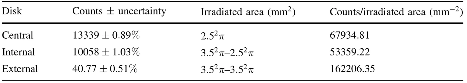
Table 2 Counts for the second set of disks

Table 3 Irradiation system activation experimental data
The second result acquired is the activation profile on a real target, or how spread this activation was. Two experiments consisted of irradiating two sets (with three pieces each) of 2-mm-thick AISI 316 steel disks with 31.8 mm external diameter.In each set,one disk has a 5.4 mm hole,one a 7.4 mm hole, and the last one is whole, as shown in Fig. 10.
Both sets were irradiated using the same geometry,except that for the second set we used the 9-mm collimator at the target holder, sitting a distance of 42 mm from the first disk. This collimator adds information regarding how much the proton beam is spread further than 9 mm from the center. As we had iron-rich disks being activated by protons, we observed56Co and57Co to obtain activation/activity data.
By comparing the total activity from each disk, we obtained the results as to how often the proton beam goes further than 5.4 mm and 7.4 mm from the center. Tables 1 and 2 contain information on how much relative activity we found on each disk from the first and second sets,respectively. These counts are solely of gamma emission from the 847 keV56Co peak.
The complete information for these experiments is shown in Table 3.
From these data, we are also able to ascertain many parameters that were subsequently used and considered in conformity. We also list the gamma spectrum from each disk and calibration source on both sets. In the experiment using the first set of disks, we obtained the gamma spectrum present in Fig. 11, which refers to the152Eu calibration source (seen in Fig. 12), and they serve as a reference for gamma spectrum acquisition.

Table 4 R2 coefficient by irradiation depth
After obtaining positive results on the irradiation system’s efficiency, stability, and optical quality, the attenuation system’s resulting activation profile follows.
3.2 Activation profile
This analysis was conducted by comparing calibration curves.These consist of functions based on each foil’s total activity × depth of said foil, which gives us the effective activation profile. The compared calibration curves are direct irradiation (first set of foils) against attenuationsystem-aided irradiation(second set of foils).Figure 13a,b shows the direct and attenuation-system-aided activation profiles, respectively.
Figure 13a shows that unaided irradiation results in a Gaussian, which is expected, given the cross section’s characteristics for this reaction, but troublesome to work with on TLA experiments, which depend on constant activation from the surface to a certain depth [16]. Figure 13b shows how an attenuation-system-aided irradiation gives the desired constant activation up to a certain depth,visually around 300 μm depending on precision requirements.
Another result that can be observed is the integrated activation by depth, which tells us how far the activation reaches in a steel solid target, as shown in Fig. 14a, b for direct and indirect irradiation, respectively.
From these graphics, we can also observe that the second set shows a straighter line from 0 to 0.4 mm depth.This result is important because it eases measurements on a variety of TLA applications [16]. Thus, Table 4 displays how straight these lines are based on R2coefficients.
Visually, we can see how straight our effective activation lines are by comparing them to R2= 1 straight lines.Figure 15 shows the results for direct irradiation (first set),and Fig. 16 shows the results for irradiation through the attenuation system.
4 Conclusion
First, we calculated which energy quantization in our proton beam would result in a normalized activation profile up to 300 μm on56Fe-rich targets. Subsequently, we determined how thick each of the Attenuation Wheel’s foils should be to obtain the calculated energy values.After these calculations, the Attenuation Wheel was built in a way that also allows for different foil configurations for other targets and studies. In the meantime, we also developed and implemented the necessary systems for good optical quality in the irradiation line’s proton beam,including current measurements, beam stop, cooling, and vacuum systems. After the said construction,we irradiated two sets of AISI 316 steel foils and measured their total activity to obtain two activation profiles. The second one,which counted on our device to quantize the proton beam’s energy, shows a constant activation up to a depth of 300 μm, demonstrated by R2coefficients close to 1.
This last experiment attests that this method and our built system are ready for TLA applications using both the regular method (with reduced depth) and our contribution to this field: new applications with a greater depth of analysis. The methodology adopted here also grants versatility as new calculations for different reactions are simple and the geometry used allows several kinds of solid targets,including proton beam sources with greater energy,allowing an even greater depth of normalized activation.
Regarding how precisely experiments using this method would perform, we have discussed and demonstrated activation statistical uncertainty for our method in Figs.13 and 14. We also have our CV-28 with a beam energy uncertainty sitting at ±1.25%; compared to this, Tantalum gate window thickness is negligible. Subsequently, for the aluminum foil thicknesses we have a ±2% uncertainty,which could improve with better material. These are the factors addressed in this paper; the remaining factors are the detection system used and the target’s chemical composition precision.
For further applications, our proposal is to apply the TLA technique in practical wear studies, which is already in progress as of September 2019.
杂志排行

Nuclear Science and Techniques的其它文章
- Effect of 37Cl enrichment on neutrons in a molten chloride salt fast reactor
- Spin coating of TPB film on acrylic substrate and measurement of its wavelength shifting efficiency
- Optimization of the S-band side-coupled cavities for proton acceleration
- Multi-frequency point supported LLRF front-end for CiADS wide-bandwidth application
- Recent studies on potential accident-tolerant fuel-cladding systems in light water reactors
- Complex structure of human Hsp90N and a novel small inhibitor FS5