Simulation of arcs for DC relay considering different impacts
2020-03-09KeyaoHUANG黄珂瑶HaoSUN孙昊ChunpingNIU纽春萍YiWU吴翊MingzheRONG荣命哲GuangchaoYAN闫广超andGuangminHUANG黄广明
Keyao HUANG (黄珂瑶), Hao SUN (孙昊),3, Chunping NIU (纽春萍),Yi WU (吴翊), Mingzhe RONG (荣命哲), Guangchao YAN (闫广超) and Guangmin HUANG (黄广明)
1 State Key Laboratory of Electrical Insulation and Power Equipment, Xi’an Jiaotong University, Xi’an 710049, People’s Republic of China
2 HUAWEI Technologies Co., Ltd., Shenzhen 518129, People’s Republic of China
Abstract Recently DC relay has been concerned as a key component in DC power distribution,management and control systems like aircraft, new energy vehicle, IT and communication industries. Ordinarily, magnetic force and contact moving speed have great influence on arc behaviours in the breaking process. This paper focuses on the numerical investigation of arc during the contact opening process in a real 400 V/20 A DC relay product coupling with an inductive load circuit.A 3D air arc model based on the magneto-hydrodynamic theory was built and calculated. A method coupling different computational software was used to take the nonlinear permanent magnet and contact opening process into consideration simultaneously.Arc behaviours under different magnetic field and contact opening speed were presented and discussed carefully. It has been found that the increase of the magnetic field is beneficial to the quick build-up of arc length and voltage. Arc breaking duration becomes shorter with the increase in contact opening speed from 63.5 rad s−1 to 94.5 rad s−1, such reduction is less significant with an increase of opening speed from 94.5 rad s−1 to 118.5 rad s−1.
Keywords: DC relay, arc motion, magnetic field, opening speed
1. Introduction
Arc burns between contacts during the interruption operation of DC relay. Since there is no natural zero-crossing point for DC system, measures must be taken to extinguish arc. DC relay widely used in hybrid vehicles and communication industry features with small size and compact structure,which means it is difficult to improve the breaking ability by means of gassing materials or splitters. Early studies on DC relay shows that the magnetic field and contact opening speed have great influence on the arc breaking process. Therefore,investigation on the detailed arc behaviours under different conditions helps to figure out the mechanisms, which is of great importance to optimize the design of DC relay.
Many experiments and simulations have been carried out to analyze the DC arc. Lindmayer focused on the effect of strong magnetic blow fields in DC arc interruption by simulation [1]. Ma et al [2] studied the arc motion and the influence of chamber width with both experimental and numerical approaches.In[3]and[4],the impact of magnetic field on DC breaking process was analyzed by experiments. Other researchers compared the arc behaviours under different contact opening speeds in [5-7]. It is still difficult to obtain intuitive behaviours and detailed parameters of arc. With the continuous development of algorithm and computing power,DC air arc model in complex relay product can be built to study the switching process carefully.
In this paper, the arc breaking process considering the moving contact in a real DC relay product was studied by means of experiments and simulations.A 3D arc model based on the magneto-hydrodynamic theory coupling with an inducive load circuit was built and calculated. The flow field and electromagnetic field were calculated separately in a different computational software to fulfil the requirement of considering nonlinear magnet material and contact opening process simultaneously. Then the arc breaking process was simulated repeatedly under different magnetic field and contact moving speed in order to analyze their influence on arc breaking process in DC relay. Simulation results of curves and distribution figures were presented to discuss the detailed arc behaviours.
2. Simulation conditions
2.1. Geometry model
Figure 1 shows the calculation model representing the DC relay which consists of AgSnO2contacts with a diameter of 2.6 mm, Nd-Fe-B permanent magnet and the arc chamber.This is the x-z plane of the three-dimensional model. The length, height, and width of the arc chamber are 28 mm,19.5 mm and 10 mm,respectively.The initial gap between the contact is set to be 0.2 mm. The moving contact rotates counter clockwise around the centre of rotation in the opening process. The area in grey is the arc chamber, which is enclosed by insulated walls filled with 1 atm air. The area in white is the electromagnetic computational field, which is necessary to maintain the accuracy.
2.2. Numerical model
The arc numerical model is based on the MHD theory,which has been widely used in circuit breakers [8-14]. The conservation equations of mass, momentum, energy and electromagnetic field are solved to describe arcing process.Considering the complexity of 3D model and computational efficiency,a few assumptions and simplifications are adopted as follows:
· Plasma in the arc chamber is in a state of local thermal equilibrium (LTE).

Figure 2.The circuit diagram for DC relay.
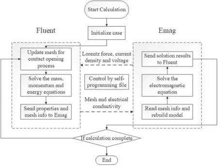
Figure 3.Flow chart of calculation process.
· Metal erosion and insulation wall ablation are not considered in the simulation.
· Arc ignition process is not included in the simulation.The calculation starts with a fixed temperature distribution of 10 000 K between two contacts.
The thermodynamic coefficients and transport coefficients of real air plasma in wide range of temperature and pressure are taken from one of the members in our research group Wang [15].
For temperature boundary, all the inner wall surfaces of the model are set to be a static temperature of 300 K. The interfaces between air fluid and metal contacts are set with a heat flux governed by equation(1),where d is the thickness of the interface, k is the thermal conductivity, T and T0are temperature of fluid and metal, respectively.
For the pressure boundary,no pressure outlet is set since the chamber of the DC relay is closed.Non-slip conditions are imposed for the momentum equations.
For the electromagnetic boundary,the input variable is a current curve calculated according to the circuit diagram shown in figure 2, which is the same as the experimental circuit. The current input and output surfaces are shown in figure 1. The input surface is set with the time dependent current, and the output surface is set to be 0 V. In the DC circuit, Upstands for the arc voltage of DC relay. The other circuit parameters are source voltage Us=400 V, R= 20 Ω,L =0.01 mH. The calculation begins with the initial current I=20 A and arc voltage Up=0V.
2.3. Calculated method
As mentioned above, two different commercial software are used to calculate this DC air arc in order to take both nonlinear magnetic material and contact opening process into consideration simultaneously. Equations related to the flow field, like mass, momentum and energy, are calculated in the computational fluid dynamic software FLUENT, while the electromagnetic equations are solved by Ansys Emag.The FEA solver of ANSYS maintains a considerable computing accuracy even at the boundaries, which is superior to the FVM solver of FLUENT in the solution of electromagnetic equations. The calculation process coupling two software is shown in figure 3.
The calculation results like electrical conductivity, Lorentz force,current density and voltage need to be updated and transmitted between the two software. Considering the contact opening process,the mesh of model updates by Fluent in every time step so the time dependent mesh information should also be passed to the ANSYS solver. A C++ based self-programming file is used to control the data transmission in the calculation of the two software.
3. Simulation results
The coercivity of the Nd-Fe-B permanent magnet used in the DC relay is 1.2E + 6 A m−1,which is N50H and the average opening speed of the contact is 94.5 rad s−1. The simulated temperature distribution during arc extinguishing is shown in figure 4.This is the contour on a surface through the contacts in the x-y plane to show arc motion clearly.
The comparison of simulation and experiment arc voltage and current curves is shown in figure 5. The extinguishing process of arc can be divided into the following three periods:
(1) From t = 0 to t = 0.3 ms, the calculation starts with a simplified cylinder arc column on the centre of contact.The diameter and temperature of the initial arc column are 1.2 mm and 10 000 K, respectively. In this period,the contacts gap is still small because of the short operation time. The arc moves from the centre to the edge of contact under the influence of magnetic field and air flow while the arc voltage shows a slight increase.
(1) From t = 0.4 to 0.7 ms, the main column moves out of the gap and stays at the left edge of the contacts. With the contact opening process, the main arc column elongates and begins to bend under Lorentz force while the arc root seems to be stagnant. The distribution of high temperature gradually enlarges due to the conduction, convection and radiation effects of joule heat. In this period,the voltage clearly rises with the elongation and deformation of arc column.

Figure 4.Profiles of the simulated temperature distribution.
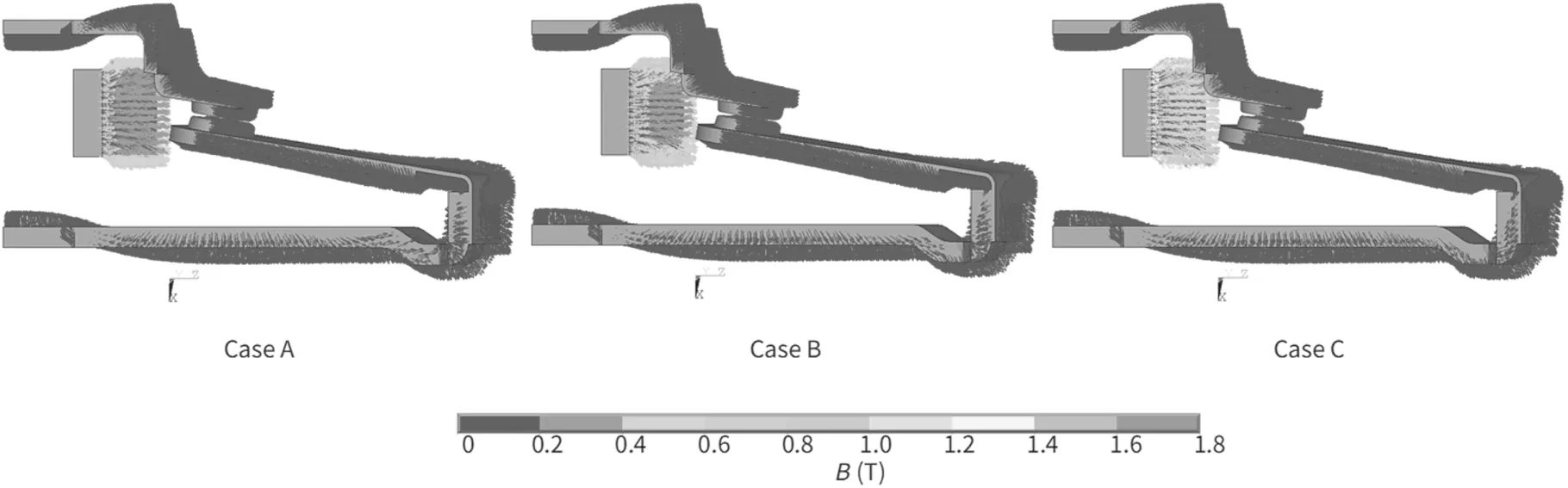
Figure 6.Magnetic flux density distribution on the model surface.
(2) After t = 0.7 ms, the arc root is no longer stagnant and shifts out of the contact. The length and voltage of arc greatly increase without the limitation of contacts. A good current limiting effect is generated in the circuit and the arc current drops simultaneously, as shown in figure 5. The temperature of arc decreases gradually since the current is not enough to keep burning,leading to the extinguishing of arc.
The trends of calculated results show general agreement with the curves obtained in the experiments. However,experiment results show obvious variation in the voltage and current curves. This kind of fluctuation is usually associated to the re-strike of arc.In the real interrupting process,there is intense and complex interaction between the arc and the contact, like erosion, vaporization of metal and droplet injection [16]. Those will greatly influence the property of plasma as well as the distribution of flow field[17,18],which is ignored in our current simulation now. Another possible reason is that the opening speed is an average constant in our simulation work for simplification while in the real case the contact separation is an acceleration process with contact spring. These differences lead to a more stable arc in the simulation work compared with the often re-strike phenomenon in experiment.
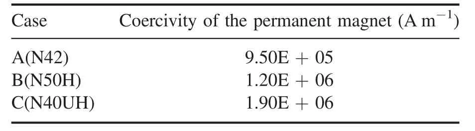
Table 1.Different magnet case for simulations.
4. Comparison of different impacts
To figure out the influence of different impacts on the arc extinguishing process,with the same numerical and geometry model,simulations under different magnetic field and contact opening speed were carried out.
4.1. Arc behaviors under different magnetic fields
Besides the permanent magnet of N50H used in the DC relay,other two cases of different magnets, as shown in table 1,were simulated for comparative research. All the other parameters remain the same between the cases.The magnetic flux density distribution on the surfaces of permanent magnet and contacts is shown in figure 6. The magnetic flux density provided by current flowing through the contacts is several orders of magnitude lower than that of permanent magnet. It can be clearly seen that the magnetic flux density of permanent magnet is A < B < C.
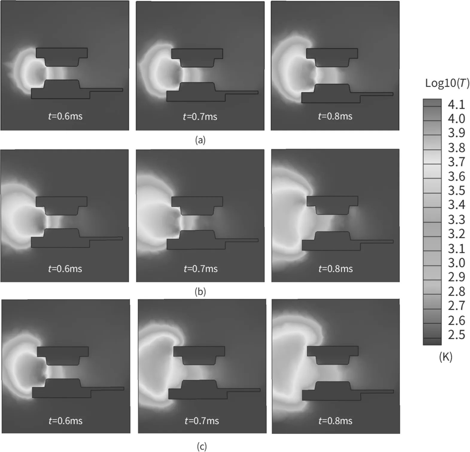
Figure 7.Temperature distribution of (a) case A (b) case B and (c) case C.
The temperature distributions of three cases on the surface through the contacts in the x-y plane, are shown in figure 7. In order to analyze the effect of coercivity of the permanent magnet,comparisons of simulated arc voltages are shown in figure 8. It demonstrates that the arc voltage rises faster and the ‘shifting-out’ process of arc roots happens earlier with a stronger magnetic field.
It should be noted that before t = 0.6 ms, temperature distributions of the three cases are quite similar with the arc root staying stagnant at the edge of the contact. After t = 0.6 ms, the arc motion shows great differences with the increase of coercivity. At t = 0.7 ms, the arc roots have already shifted out of the contact gap in case C while the same process happens in case B after t = 0.7 ms. In case A with the lowest coercivity, the arc roots seem to be stagnant and the‘shifting-out’process does not happen till t = 0.8 ms.Similar tendency can also be seen in the arc voltage curves. The arc voltage increases by 23.1% and 36.2% when the coercivity of magnet increases from 0.95E + 5 to 1.90E + 5 A m−1at t = 0.6 ms.This increase rises to 38.7%and 194.3% at t = 0.7 ms.
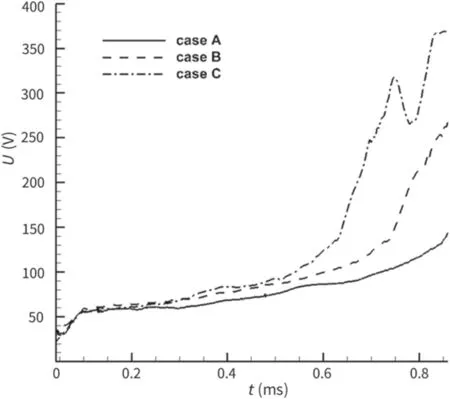
Figure 8.Simulated voltage of the three cases with different coercivities of the permanent magnet.
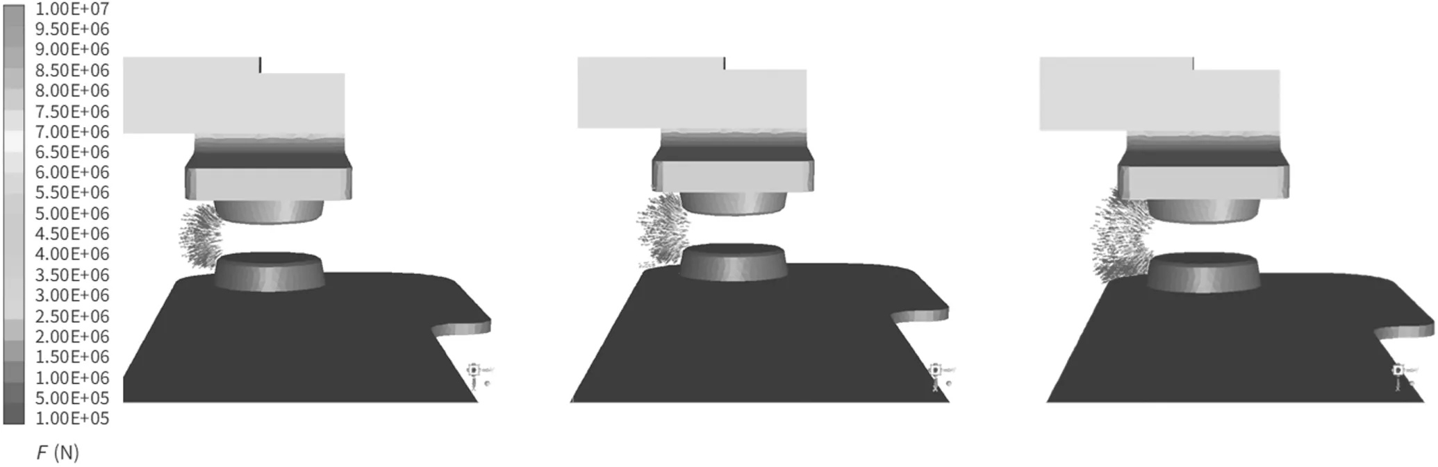
Figure 9.Distribution of Lorentz force vector at t = 0.6 ms for A, B, and C cases.
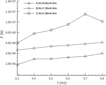
Figure 10. The maximum of the Lorentz force in the three cases.
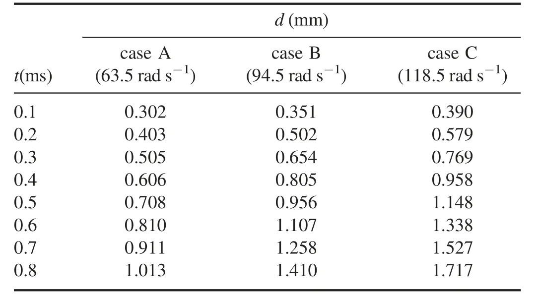
Table 2.Distances between contacts gap in the simulation cases.
This can be explained by the differences of Lorentz forces,as can be seen in figures 9 and 10.This kind of force,formed by the transversal magnetic field of permanent magnet, is perpendicular to the column and pointing to the direction of arc motion, which plays an important role in the movement of arc. It can be seen clearly in figure 9 that the maximum value of force appears near the arc roots on the contact,where the current density is high,and the force is greater with stronger magnetic field.Therefore,the arc motion is fastest in case C, followed by B and A. In figure 10, the maximum of Lorentz force increases with the opening of contacts. The arc column is quite short due to the small contacts gap initially, thus the contribution of magnetic force is negligible with small arc length. With the increase of the length,the influence of Lorentz force on arc column becomes obvious.
It can be seen in figure 10 that at t = 0.8 ms,the force in case C starts to drop. However, it continues rising in other two cases.In case C with the strongest magnetic field,the arc voltage grows fast,leading to a quick decrease of arc current.The current value in case C at t = 0.8 ms is 5.0 A, which is lower than that in other two cases.Another possible reason is that in case C,the arc column has moved out of the contact at t = 0.8 ms and is away from the centre of the magnetic field.These altogether result in the drop of the magnetic force at t = 0.8 ms in case C.
It can be obtained in figure 8 that there is a voltage drop in case C at t = 0.75 ms. The distribution of current density vector on the stationary contact in case C around t = 0.7 ms is shown in figure 11. From t = 0.68-0.72 ms, the arc root moves from bottom side to upside along the edge of contact.Arc moves rapidly with large magnetic force in case C,leaving an accumulation of hot gas between the contacts as shown in figure 12. At t = 0.74 ms, the back commutation occurs as a new parallel arc root forms near the bottom side,which is below the original column and corresponds to the area of accumulation of hot gas. The new arc replaces the original one gradually from t = 0.74-0.78 ms. This process of arc back strike leads to the arc voltage drop in case C.
4.2. Arc behavior under different opening speeds
The average contact opening speed in the DC relay is 94.5 rad s−1, and other two cases with opening speed of 63.5 rad s−1and 118.5 rad s−1were simulated for comparative research. The distances between the contacts gap are shown is table 2 from t = 0.1 to 0.8 ms for each case.All the other parameters remain the same between those cases.
The simulated voltage with different opening speeds is shown in figure 13.The arc column elongates faster with larger opening speed,which is beneficial to the increase of arc voltage and the limiting effect of current. When speed = 63.5 rad s−1,arc voltage grows slowly and it takes a long time for the DC relay to extinguish arc. When speed = 94.5 and 118.5 rad s−1,the time required for the arc voltage to reach specific magnitude is shown in figure 14.
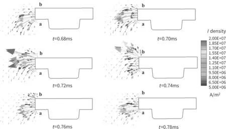
Figure 11.Distribution of current density vector on the stationary contact in case C.
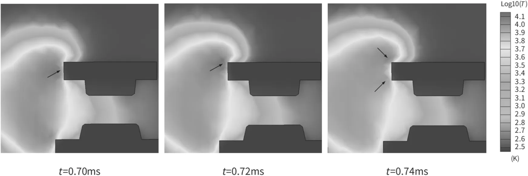
Figure 12.Distribution of temperature near the contact in case C.
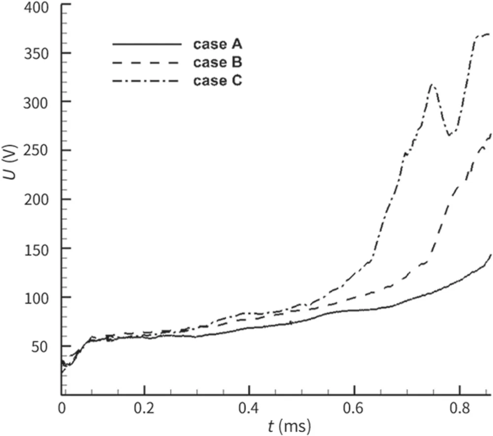
Figure 13.Simulated voltage curves of A, B, and C cases.
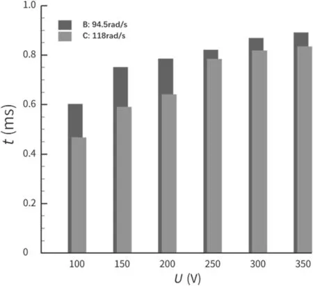
Figure 14.Time required for the arc voltage to reach specific magnitude in cases B and C.

Figure 15.Comparison of velocity vector and current density vector distribution of (a) case B and (b) case C (left: vector distribution at t = 0.65 ms, right: vector distribution at t = 0.75 ms).
It is found that in case C (v = 118 rad s−1), it takes obviously shorter time for arc voltage to reach 100, 150 and 200 V compared with case B. The high opening speed leads to a large contact gap and quick elongation of the arc column,therefore the voltage increases rapidly. However, this tendency is weakened after t = 0.6 ms. A stagnation can be observed on the voltage increasing curve in case C at around t = 0.70 ms, as shown in figure 13, and the time required to reach 250,300 and 350 V is relatively close in cases B and C.
In order to analyze the effect of opening speed, the comparison of velocity vector distribution and Lorentz force vector distribution in cases B and C is shown in figures 15(a)and(b).Comparing the results,it can be found that there is a huge airflow and magnetic force vertical to the arc column in case B. It promotes the rapid movement of arc root and elongation of arc column during this period, and the column‘shifting-out process’ happens. While in case C, the airflow weakens after t = 0.55 ms, and the magnetic force mainly acts on arc root instead of arc column compared with that in case B.
So, one possible reason is that in case C at t = 0.7 ms,the arc current is quite low due to the rapid voltage increase with high contact speed, leading to the weak Lorentz force and airflow. In addition, a faster decrease in arc current density causes an increase in a di/dt value, which induces a large voltage in this kind of inductive load circuit, possibly leading to slower arc extinction. Altogether, these result in a stagnation of arc roots as well as a stagnation in voltage growth. Break arc durations are similar in cases B and C.
From these results,we find the following fact interesting;increasing the opening speed of contacts is beneficial to the arc column elongation and arc voltage increase, which helps to extinguish the arc in a shorter time.However,the influence of the opening speed on extinguishing is weakened when the speed is high enough. This phenomenon shows a good agreement with the experiment results of Bo et al [19] and Hasegawa et al [20]. Additionally, the rapid rise of arc voltage also increases the risk of restrike between contacts with small opening gap at the initial stage. Careful consideration needs to be taken regarding the opening speed of contacts in the design of DC relay.
5. Conclusion
A 3D model based on a kind of real high-voltage DC relay product is investigated,which takes the non-linear permanent magnet and contact opening process into consideration. The behaviours of arc plasma are studied in this paper and the influences of contact opening speed and magnetic field are also figured out by simulation comparisons. The important findings are as follows:
· The arc behaviour is obtained during the burning process and an obvious arc root shifting phenomenon is observed in the simulation result, which can be supported by the experiment curve.
· Increasing the magnetic field helps to extinguish the arc in the DC relay. Arc columns move quickly with larger electromagnetic force and leave an accumulation of hot gas between the contact, which results in the back commutation and arc voltage drops in some cases.
· Increasing the opening speed of contacts is beneficial to the arc column elongation and arc voltage increase,leading to a shorter arc duration.However,such reduction tendencies become less significant when the opening speed is high enough.It is of great importance to choose a proper value of contact opening speed in the design of the DC relay.
It should be admitted that this simulation model still has some deficiencies, like the ignoration of interaction between arc and contact and the simplification of a constant opening speed, which may lead to the differences like re-strike phenomenon between the real opening process and simulation condition. More consideration will be taken in these aspects to improve simulation accuracy in the future.
Acknowledgments
This work was supported by National Natural Science Foundation of China (Nos. 51707144, 51877165 and 51577144) and Shaanxi Province Key R&D Program under 2019ZDLGY18-05. This manuscript is recommended by international symposium on insulation and discharge computation for power equipment IDCOMPU2019.
猜你喜欢
杂志排行

Plasma Science and Technology的其它文章
- Analysis of the characteristics of the plasma of an RF driven ion source for a neutral beam injector
- Synthesis of vertical graphene nanowalls by cracking n-dodecane using RF inductivelycoupled plasma-enhanced chemical vapor deposition
- Application of persulfate in low-temperature atmospheric-pressure plasma jet for enhanced treatment of onychomycosis
- Magnetic field enhanced radio frequency ion source and its application for Siincorporation diamond-like carbon film preparation
- Microwave frequency downshift in the timevarying collision plasma
- Comparison of Reynolds average Navier-Stokes turbulence models in numerical simulations of the DC arc plasma torch