Beamforming analysis based on CSB sin-FDA
2020-02-26WANGBoXIEJunweiZHANGJingandZHANGHaowei
WANG Bo,XIE Junwei,ZHANG Jing,and ZHANG Haowei
1.Air and Missile Defense College,Air Force Engineering University,Xi’an 710051,China;2.Highway Railway College,Shaanxi Vocational and Technical College of Transport,Xi’an 710018,China
Abstract: This paper studies the adaptive beamforming algorithm based on the frequency diverse array (FDA) array where the interference is located at the same angle (but different range)with the target. We take the cross subarray-based FDA with sinusoidal frequency offset (CSB sin-FDA) as the receiving array instead of the basic FDA. The sampling covariance matrix under insufficient snapshot can be corrected by the automatic diagonal loading method. On the basis of decomposing the mismatched steering vector error into a vertical component and a parallel one,this paper searches the vertical component of the error by the quadratic constraint method.The numerical simulation verifies that the beamformer based on the CSB sin-FDA can effectively hold the mainlobe at the target position when the snapshot is insufficient or the steering vector is mismatched.
Keywords:receiving processing architectures,minimum variance distortionless response (MVDR) beamformer, cross subarraybased frequency diverse array with sinusoidal frequency offset(CSB sin-FDA),steering vector,snapshots.
1.Introduction
The frequency diverse array(FDA)was initially designed by Antonik to form a range-dependent beampattern [1].In contrast to the phased array (PA), the FDA employs a tiny frequency increment relative to the carrier frequency across the antenna elements and it results in a rangeangle-dependent beampattern[2,3]. Due to the additional controllable degrees of freedom (DOF) of the array [4],the FDA has sparked many interesting investigations such as wireless communications[5], space-time adaptive processing [6], cognitive radar [7], clutter and jamming suppression [8], etc. Multiple-input multiple-output(MIMO)combined with FDA radar, named the FDA based on MIMO (FDA-MIMO), which can provide more DOF in the transmit-receive domains,has also been explored in recent years[9–13].
However, limited paper on the subject of FDA in electronic countermeasures scenarios has been published.With an outline of the current research status of the FDA radar,Ahmed et al. [14] introduced why the FDA is appropriate to electronic counter-countermeasures demands.Xu et al. [15] dealt with the interference suppression based on the adaptive receive beamforming analysis of the FDA radar,but the inherent range-angle coupling was not taken into consideration. The FDA was investigated in [16] as a range-dependent beam with applications in suppressing range ambiguous clutter. Lan et al. [17] proposed an approach to suppress the mainlobe range deceptive jamming by utilizing the range-angle-dependentcharacteristic of the FDA-MIMO radar.
The PA cannot suppress the mainlobe interferences that are located at the same angle (but different ranges) with that of the target.The FDA is well known for its additional DOF in the range dimension,which offers an opportunity to overcome this problem. There is range-angle coupling inherent in the transmit beampattern of the basic FDA because of the linear incremental synchronization between the element spacing and the linear frequency offset.In order to eliminate the inherent range-angle coupled relationship, useful achievements have been obtained which can be divided into two categories. One category is based on the design of the frequency increment or transmit weight[18–22].The other category is based on the design of the array configuration[23–26].Considering the range-angle coupling inherent in the transmit beampattern of the basic FDA,we propose a cross subarray-based FDA used as the receiving array to form a dot-shaped beampattern without periodicity in the maximum rather than the S-shaped beampattern.
In modern warfare, supportive interference is a commonly used interference pattern in the electronic warfare.The supporting jammer is able to form strong interference fans in the combat area by releasing strong noises or dense false target signals outside the defense zone to cover the penetration of combat aircraft. The feature of the support jammer is that the interference source and the target are on different platforms. Therefore, through the spatial domain filtering, the target direction receive gain can be maximized and the interference direction gain can be set to zero, so as to minimize the interference to become an important means of radar electronic countermeasures. Beamformers are generally designed based on a certain criterion to determine the optimal weight vector.Among them,the minimum variance distortionless response (MVDR) beamformer, which is simple in principle, has been widely used [27]. The two-sided MVDR(TS-MVDR) beamformer based on FDA-MIMO can effectively reduce the complexity of the MVDR beamformer.However,the performance of the TS-MVDR beamformer will also degrade dramatically when the steering vector is mismatched or the snapshot is insufficient[28].This paper mainly works on this problem.
The remaining sections are organized as follows. Section 2 analyzes the data basis of this paper. In Section 3,beamforming basis of the MVDR based on FDA with frequency filter (FDA-BFF), the MVDR based on FDAMIMO, the TS-MVDR based on FDA-MIMO are analyzed.In Section 4,we take the cross subarray-based FDA with sinusoidal frequency offset(CSB sin-FDA)as the receiving array. Then we correct the mismatched steering vector and the covariance matrix under insufficient snapshot respectively.Simulation results and analysis have confirmed the effectiveness of the proposed method in Section 5.Section 6 presents our conclusions.
2.Data basis
2.1 Data model of FDA
The configuration of the basic FDA is shown in Fig.1.The frequency radiated from thenth element will be

wheref0is the carrier frequency (also the radiation frequency of the reference element),Δfis the frequency increment,Nis the number of the antenna elements.

Fig.1 Configuration of the basic FDA
Under the narrowband assumption,the monochromatic continuous signal transmitted by thenth element can be given as

The signal received by a specific far-field location with the angleθand the slant rangeRfor the first element is a superposition of the delayed and attenuated version of the transmitted signal:

wherern=R-ndsinθis the range of the target from thenth antenna element,ddenotes the element spacing,andcis the speed of light.Hence,the total electric field observed at the far field point(R,θ)is computed as

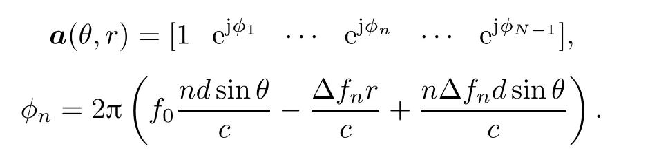
wherefe(ω0+nΔω) denotes the array directional function.Considering that a target locates at(R,θ),the steering vectora(R,θ)can be expressed as
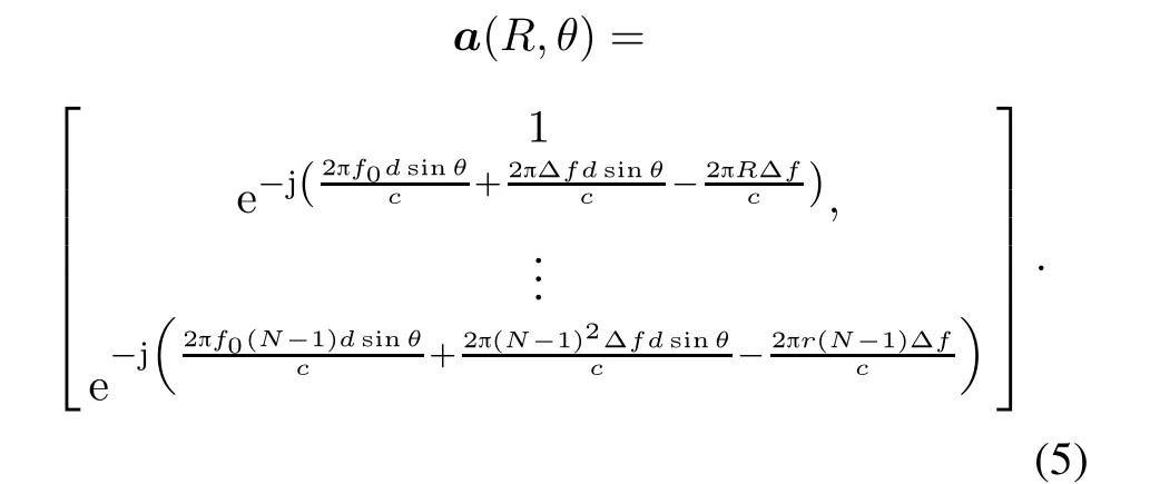
According to (5), the term of 2π(N -1)2Δfdsinθ/ccan be approximated as a function of the number of array elements. Its change in value is shown in Fig. 2, whereψ= 2π(N -1)2Δfdsinθ/c.It can be seen from Fig. 2 that if the number of array elements is no more than 60,thenψwill be smaller than π/4.This implies that the approximation errors are ignorable.
Considering the assumption thatfe(ω0+nΔω)≈fe(ω0),(4)can be rewritten as


Fig.2 ψ changes as a function of the array elements
The array factor seen at the target position(R,θ)can be derived as

whereφ=2πf(t-R/c)-π(N-1)Δft-π(N-1)Δf+π(N -1)Δfdf0sinθ.
2.2 Three receiving processing architectures
Weight the transmitted signal in (3) to reach the far field target(R0,θ0):

The signal reflected by the target(R0,θ0) and then received by themth element of the receiving array can be written as
The reflected signal received by themth element contains the reflected energy radiated by all the array elements in the transmitting array.The processing of the FDA radar receiving signals can be divided into three different architectures by accessing different filters after the receiving array elements.The goal for each architectures is to put the maximum possible signal at the target location.
The first processing architecture is called “Bandlimited, Coherent FDA”. The “Band-limited, Coherent FDA” is actually equivalent to the FDA-BFF architecture [29]. Only the signal with the carrier frequencyfmcan be filtered out in themth channel by the narrowband filter:

The second processing architecture is called“Full-band,Coherent FDA” [29]. The “Full-band, Coherent FDA” is actually equivalent to the FDA-MIMO architecture. This processing architecture can obtain theN×Ndimensional matrix by rearranging the receiving signals. This architecture is able to simultaneously weight the phase at the transmitting/receiving end.For each receive antenna of the array withNelements, the received signals can be decomposed byNnarrowband filters.The separated signals can be rearranged according to theNreceiving channels,yieldingN ×Nisolated waveforms:

The third processing architecture is called “Full-band,Pseudo-coherent FDA” [29]. The “Full-band, Pseudocoherent FDA”is actually equivalent to the FDA transmitting with PA receiver(FDA-PA)architecture.Bandpass filters are used in this architecture to receive the reflected energy radiated by all the array elements in each receiving channel:

The beampattern of the “Full-band, Pseudo-coherent FDA” has the problem of the mainlobe distortion. Its application value in practice is low. We will not do specific analysis on the “Full-band, Pseudo-coherent FDA” architecture in this paper.
3.Beamforming basis
The target can be approximated as a point when there are only a few point sources of interference such as the suppressed positive interference around the target. The zerovalue filter can filter out the interference by aligning the beampattern nulls point to the interference. The goal of zero-value filters is suppressing the interference and noise as well as preserving a unity gain for the desired signal.Beamformers are generally designed based on a certain criterion to determine the optimal weight vector. Among them, the MVDR beamformer, which can form effective nulls in the interference zone,is widely used.
3.1 Data model of MVDR beamformer
Considering a far-field target locates at (Rs,θs), and a set of interference impinging upon the array from(Ri,θi) (i= 1,2,...,N -1), the received signal of the PA withNelements can be given as

whereJ(t) = [j1(t),...,jN-1(t)] denotes the interference signal set.The receiving steering vectora(θ)is

The output of the PA is

wherewis the receive weight vector,[]Hdenotes the congjugate transposition,andn(t)is the receive noise vector.
The goal of the MVDR weighting method is solving the following two problems: (i) minimizing the power of interference and noise; (ii) preserving a unity gain for the desired signal.Consequently,the MVDR optimal function can be formulated as

The optimal weight vector will be
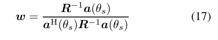
whereR=E[xJ(t)xHJ(t)],xJ(t)=J(t)+n(t).
The output performance of the beamformer is usually expressed as the signal to interference plus noise ratio(SINR)[30]:

3.2 Application of MVDR beamformer
Substituting the steering vector of each structure into(16)to obtain the optimal weight vectors of the receiving processing architectures mentioned above.
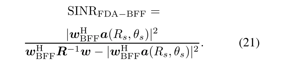
The output of the FDA-BFF can be written as

where,and*represents the Hadamard product.
The optimal weight vector of the FDA-BFF will be

The output SINR of the FDA-BFF can be written as
The output of the FDA-MIMO array is

where⊗represents the Kronecker product.
The FDA-MIMO architecture can be virtualized as a combination of FDA transmitted modulation and PA weighted reception. The virtual transmit steering vectora(Rs,θs) anda(Ri,θi) of FDA can be expressed based on(19).The receiving virtual steering vector of PA can be given as

The optimal weight vector of FDA-MIMO will be

The output SINR of FDA-MIMO can be written as

In order to solve the problem of high computational complexity in MVDR based on FDA-MIMO.Considering that the Kronecker structure of the FDA-MIMO steering vector can be fully utilized, we obtain the optimal weight vector by TS-MVDR. The FDA-MIMO architecture can be virtualized as a combination of FDA transmitted modulation and PA weighted reception.The optimal weight vectors,which consist ofa(R,θ)andb(θ),can be calculated respectively based on(17).Then we take the two optimal weight vector Kronecker products to obtain the optimal weight vectors of the TS-MVDR based on FDA-MIMO.The process[31]can be formulated as

In order to obtain the optimal weight vector of the MVDR beamformer,N2coefficient vectors need to be calculated according to (13). If the optimal weight vectors,which consist ofa(R,θ) andb(θ), can be calculated respectively,then only 2Ncoefficient vectors need to be calculated if we take the two optimal weight vector Kronecker products.
4.Proposed method
The output performance of MVDR based on the FDA-BFF and TS-MVDR based on FDA-MIMO will both degrade when the steering vector is mismatched or the snapshot number is insufficient.We propose a method to solve this problem in this section.
4.1 CSB sin-FDA
The beampattern decoupling method based on the nonlinear frequency offset is the premise for suppressing rangerelated interference.In this section,we analyze the rangeangle joint estimation performance of the FDA by using four different nonlinear frequency offsets. Then it can be used as a criterion for nonlinear frequency offset selection.
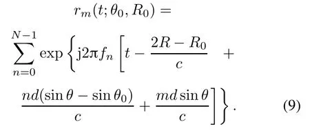
ConsideringLtargets located in the space,the FDA array received signal obtained by matched filtering can be given as

whereαldenotes the target reflection coefficient,ndenotes Gaussian white noise,ais the steering vector, andwu=ais the reception weight vector.
When the target position is determined, the delayτcan be formulated by the target azimuthθand the slant ranger,and(27)can be rewritten as

where
The received signal covariance matrix will be

whereis the noise mean square error,andIdenotes the unit matrix,
Then, the eigenvalue decomposition of the covariance matrix is performed. The eigenvalues are rearranged according to their value of them. The eigenvectors corresponding to the eigenvalues are regarded as the signal subspace.The remaining eigenvectors are regarded as the noise subspace.Finally,calculate the peak of spectral function according to(26):

wherear(θ,t) denotes the steering vector, andUnis the signal subspace.
Considering a far-field target located at (0°,500 km),Fig. 3 shows the multiple signal classification (MUSIC) spectrum of the basic FDA with logarithmic, sinusoidal, cubic and reciprocal frequency offset respectively.The FDA with sinusoidally increasing frequency offset,called the sin-FDA, has remarkable performance advantages [18–26]. Therefore, we consider introducing a sinusoidally increasing frequency offset into the subarraybased FDA(SB-FDA).

Fig.3 MUSIC spectrum(θ0 =0°,R0 =500 km)
The essence of SB-FDA is to divide the uniform linear array FDA(ULA-FDA)into multiple subarrays,which employ the same/distinct frequency increments. As a result,the target’s range and angle will be estimated directly from the transmit-receiver beamforming output peak with high accurateness. The CSB sin-FDA divides the basic FDA into two subarrays with sinusoidal frequency offset as shown in Fig.4.
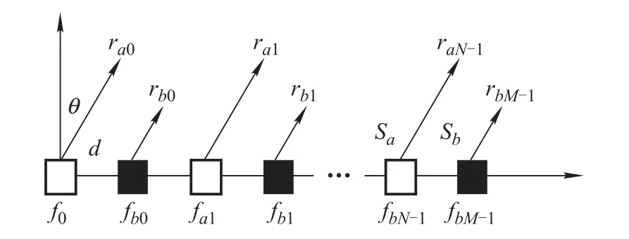
Fig.4 Configuration of CSB sin-FDA
Under narrowband conditions,the signal arriving at the far field observation point (R,θ) which is transmitted by theNth element of subarrayaand theMth element of subarraybcan be written as

whereddenotes the element spacing,NandMrepresent the number of array elements of the subarrayaand subarrayb,respectively.
Most of the existing FDA beamforming approaches focus on transmit beamforming.Less attention has been paid to FDA beamforming on receiving.In this paper,we take the CSB sin-FDA as the receiving array instead of the basic ULA-FDA.
4.2 Correction of covariance matrix
The uncorrelated hypothesis between the desired signal,the interference signal and noise will be broken with insufficient snapshot number.The diffusion of the small eigenvalues of the sampling covariance matrix will result in participation of eigenvector disturbance in the calculation of the weights.Finally it will result in a severe degradation in the output performance of the beamformer.
The modified covariance matrix can be estimated by the convex linear combination of the identity matrixIand the sample covariance matrix.Thereby reducing the small eigenvalue diffusion of the sample covariance matrix[32–34]:

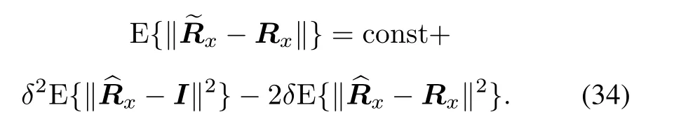
Minimize the above formula:

The reconstruction of the interference covariance matrix by using the capon spectrum can be formulated as
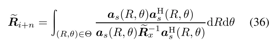
whereas(R,θ) represents the steering vector pointing to(R,θ). Θ denotes the space where the interference signal is located.
4.3 Correction of steering vector
The correction of the covariance matrix under insufficient snapshot cannot completely solve the steering vector mismatch of the desired signal.It also needs to adaptively estimate the optimal steering vector of the desired signal.The estimate of the steering vectoras(R,θ) can be translated into an estimation of the steering vector errore.The steering vector errorecan be decomposed into a perpendicular portione⊥(perpendicular to the presumed steering vectoras(R,θ)) and a parallel portione//(parallel to the presumed steering vectoras(R,θ)).e//does not affect the output SINR. As a result, the estimation of the optimal steering vector can be simplified as the search of the perpendicular portione⊥[35]:

The purpose of the objective function is to maximize the output power of the array.The first constraint ensures thate⊥is perpendicular to the presumed steering vector. The second constraint prevents the linear combinationas(R,θ)+e⊥from converging.Considering the positive definite,the optimization problem is a solvable quadratic constrained quadratic problem. As a result, the estimated optimal steering vector can be written as

Substituting the corrected covariance matrix and corrected optimal steering vector into the MVDR beamformer respectively, the optimal weight vector of the proposed method will be

5.Simulation results
In this section,simulations are performed to verify the effectiveness of the proposed approach.We assume a basic ULA-FDA of 20 sensors spaced a half-wavelength apart.The carrier frequencyf0is 10 GHz,and the frequency offset Δfis 10 kHz.The targets signal is reflected from location with the angle 30°and the range 30 km.
Example 1Beampattern of the three receiving processing architectures.
Fig.5 shows the beampattern of the three receiving signal processing architectures.The steering position is represented by a green circle.
It can be seen from Figs.5(a)–5(b)that both the“Bandlimited, Coherent FDA” architecture and the “Full-band,Coherent FDA”architecture can generate large gain at the desired position.While in Fig.5(c),the beampattern of the“Full-band, Pseudo-coherent FDA” architecture will have the problem of mainlobe distortion and sidelobe enhancement. As a result, we will not consider the “Full-band,Pseudo-coherent FDA” architecture in the subsequent simulations.

Fig.5 Beampattern of the three receiving processing architectures
Example 2Comparison of the beampattern based on the MVDR beamformer.
In this example, the interference locates at (31°,32 km). Fig. 6 shows the beampattern of MVDR based on PA. Fig. 7 shows the beampattern of MVDR based on FDA-BFF. Fig. 8 shows the beampattern of MVDR based on FDA-MIMO with 10 array elements. Fig. 9 shows the beampattern of MVDR based on FDA-MIMO with 20 array elements.

Fig.6 Beampattern of PA based on MVDR(N =20)

Fig.7 Beampattern of MVDR based on FDA-BFF(N =20)

Fig.8 Beampattern of MVDR based on FDA-MIMO(N =10)
Fig.9 Beampattern of MVDR based on FDA-MIMO(N =20)
PA can form a “zero-limit band” at the interference angle, which is angle-dependent and range-independent.When the interference is closer to the target in angle,problems such as mainlobe distortion will occur as shown in Fig. 6. Due to the frequency offset existing in the FDA,the beampattern of the FDA-BFF architecture is rangeangle dependent, which can minimize the power of interference and noise while preserving a unity gain for the desired signal as shown in Fig. 7. From Fig. 8 and Fig. 9,we can see that the ideal beampattern can be obtained by MVDR with 10 array elements.The power of interference and noise is minimized.The unity gain for the desired signal can be preserved. Considering an array with 20 elements, the power of interference and noise can be minimized.However,there is mainlobe distortion in the beampattern and the corresponding mainlobe cannot be found.It shows that the MVDR beamformer is not suitable for large-scale FDA-MIMO with excessive number of array elements. Therefore, we introduce the TS-MVDR beamformer into large-scale FDA-MIMO in Example 4.
Example 3Comparison of the transmit beampattern of basic ULA-FDA and CBS sin-FDA.
Fig. 10 shows the comparison of transmit beampattern of the basic ULA-FDA and the CBS sin-FDA. Due to the additional controllable DOF of the array, the FDA has sparked many interesting investigations.However,the range and angle information of the FDA cannot be exclusively determined at the output of the array because of the range-angle coupled transmit beampattern.In fact,the best decoupling approach is to form a dot-shaped beampattern rather than an S-shaped beampattern,which generates maxima at multiple ranges and angle values.Compared to the trailing beampattern of the basic ULA-FDA shown in Fig. 10(a), the transmit beampattern of the CBS sin-FDA is range-angle-decoupledby forming a dot-shaped beam in the target position.The overlay airspace of the mainlobe in Fig.10(b)can be further optimized[9,23,25].


Fig.10 Comparison of FDA transmit beampatter ns
Example 4Comparison of the beampatterns between FDA-BFF (MVDR), FDA-MIMO (TS-MVDR) and CBS sin-FDA(the proposed method).
Consider an interference impinging upon the FDA array from(42°,32 km). Fig.11 shows the beampattern of MVDR based on FDA-BFF. Fig. 12 shows the beampattern of TS-MVDR based on FDA-MIMO. Fig. 13 shows the beampattern of the proposed method based on CSB sin-FDA.

Fig.11 Beampattern of MVDR based on FDA-BFF

Fig.12 Beampattern of TS-MVDR based on FDA-MIMO
It can be seen from Fig. 11 that the mainlobe pointing offset and sidelobe enhancement will occur in the beampatterm,when the spatial position of the interference satisfies the range-angle coupling relationship of the FDA-BFF architecture.The output SINR of FDA-BFF will also degrade. As shown in Fig. 12 and Fig. 13, the beampatterns of TS-MVDR based on FDA-MIMO and the proposed method based on CSB sin-FDA can still preserve a unity gain for the desired signal.Therefore,we mainly analyze these two mechanisms in the following simulations.

Fig.13 Beampattern of proposed method based on CSB sin-FDA
Example 5Mainlobe maintaining when there is a 2°pointing error.
Consider an interference impinging upon the FDA array from (31°,33 km). In this example, we compare the beampattern of TS-MVDR based on FDA-MIMO and the beampattern of the proposed method based on the CSB sin-FDA when the steering vector is mismatched.Fig. 14 shows the beampattern of TS-MVDR based on FDAMIMO with a pointing error. Fig. 15 shows the beampattern of the proposed method based on the CSB sin-FDA with a pointing error.

Fig. 14 Beampattern of TS-MVDR based on FDA-MIMO with a pointing error
It can be seen from Fig.14 that, the TS-MVDR beamformer converges to the presumed steering vector with an error,which results in an offset in the mainlobe when there exists a pointing error.The result is consistent with the influence of the pointing error in (26) on the steering vector. The mainlobe of the proposed method can be held at the target position because of the correction of the steering vector as shown in Fig.15.The proposed method converts the estimate of the mismatched steering vector with a pointing error into an estimate of the steering vector error.On the basis of decomposing the steering vector error into a vertical component and a parallel one, the vertical component of the error is searched by the quadratic constraint. Finally, the corrected steering vector is obtained.Both methods can form effective nulls at the interference location,but the TS-MVDR beamformer forms a shallower one,which needs to be further improved.In contrast to the basic ULA-FDA based receive array structure, the beampattern based on the CSB sin-FDA receive array can form a dot-shaped mainlobe peak at the target location, which is also useful in the elimination of ambiguity in a series of subsequent analysis of target parameter estimation.

Fig. 15 Beampattern of proposed method based on CSB sin-FDA with a pointing error
Example 6Mainlobe maintaining with insufficient snapshot number.
Consider an interference impinging upon the FDA array from (23°,25 km). TakingL= 20 as the number of snapshots,this example compares the interference suppression performance of the proposed method with the TSMVDR beamformer with an insufficient snapshot number.Fig. 16 shows the beampattern of TS-MVDR based on FDA-MIMO with an insufficient snapshot number.Fig.17 shows the beampattern of the proposed method based on the CSB sin-FDA with an insufficient snapshot number.

Fig. 16 Beampattern of TS-MVDR based on FDA-MIMO with an insufficient snapshot number

Fig. 17 Beampattern of proposed method based on CSB sin-FDA with an insufficient snapshot number
In practice, the snapshot number of the received data often is insufficient, sometimes even lower than the number of array elements.It can be seen from Fig.16 that under insufficient snapshots,the diffusion of the small eigenvalues in the TS-MVDR beamformer will cause a severe degradation in the output performance because the uncorrelated hypothesis between the desired signal,the interference signal and the noise is broken.Due to the correction of the sampling covariance matrix under insufficient snapshot by the automatic diagonal loading method, the proposed method in this paper is able to maintain the target signal to be undistorted.Both methods can form effective nulls at the interference location under insufficient snapshot. Different from the basic ULA-FDA based receive array structure,the beampattern based on the CSB sin-FDA can also form a dot-shaped mainlobe peak at the target location.
Example 7Performance comparison of different architectures.
Fig.18 shows the SINR comparison between the four architectures at different interferences’angle.Fig.19 shows the SINR comparison between the four architectures with an insufficient snapshot number.Fig.20 shows the eigenvalue distribution of different covariance matrices.

Fig. 18 SINR comparison between the four architectures at different interferences’angle

Fig. 19 SINR comparison between the four architectures with an insufficient snapshot number

Fig.20 Eigenvalue distribution of different covariance matrices
It can be seen from Fig. 18 that the output SINR of the proposed method is higher than that of the other three architectures regardless of the interference angle.For TSMVDR based on FDA-MIMO and MVDR based on FDABFF,there exists a“notch”in the SINR output.The reason for the“notch”is the distortion of the mainlobe as it is analyzed in Example 4.Fig.19 shows that the performance of the proposed method is obviously better than that of other architectures with an insufficient number of snapshots.Fig. 20 shows that the small eigenvalue of the sampling covariance matrix is much smaller than that of the ideal covariance matrix under low snapshots.After automatic diagonal loading,the small eigenvalues of the modified sampled covariance matrix will approximate the small eigenvalues of the ideal covariance matrix. It also can be seen from Fig. 20 that the modified covariance matrix still has mismatch,which shows the necessity of the MVDR beamformer.As can be seen from Table 1,the method proposed in this paper also has a reduced computational complexity.

Table 1 Comparison of the operation time of the two algorithms s
6.Conclusions
The adaptive beamforming can be used to suppress the supportive interference in modern warfare.PA cannot suppress the interferences which are located at the same angle(but different ranges)with that of the target.As the FDA is an emerging new array with many promising applications and the research on FDA electronic countermeasures scenarios is still in infancy, this paper analyzes the adaptive beamforming performance of the proposed method based on the CSB-sin-FDA.We propose a dot-shaped beamforming method based on the CSB sin-FDA. Then a method which can be used to estimate the optimal weight vector of the MVDR based on CSB sin-FDA with a mismatched steering vector and an insufficient snapshot number is performed.Finally,simulation results show that the enhancement of the proposed method performance is remarkable.The proposed method is able to preserve a unity gain for the desired signal.
Acknowledgment
We want to thank our peers and administration for their valuable support.
杂志排行

Journal of Systems Engineering and Electronics的其它文章
- A method based on Chinese remainder theorem with all phase DFT for DOA estimation in sparse array
- A simplified decoding algorithm for multi-CRC polar codes
- Compressive sensing based multiuser detector for massive MBM MIMO uplink
- Joint 2D DOA and Doppler frequency estimation for L-shaped array using compressive sensing
- Carrier frequency and symbol rate estimation based on cyclic spectrum
- Attributes-based person re-identification via CNNs with coupled clusters loss