Whole-process modeling of titanium disc forming for gradient distributions of temperature and deformation
2020-02-24HongweiLIBinCHENMeiZHANJingHEXinxinSUNXinZHANG
Hongwei LI, Bin CHEN, Mei ZHAN, Jing HE, Xinxin SUN,Xin ZHANG
a State Key Laboratory of Solidification Processing, School of Materials Science and Engineering, Northwestern Polytechnical University, Xi’an 710072, China
b Shaanxi Key Laboratory of High-Performance Precision Forming Technology and Equipment, Northwestern Polytechnical University, Xi’an 710072, China
KEYWORDS Gradient distributions of temperature and deformation;Heat conduction;Heat radiation;Mold chilling;Titanium disc;Whole-process modelling
Abstract Gradient distributions of temperature and deformation (GDTD) are crucial for achieving dual-performance discs of titanium alloys which is required by the service environment of aeroengine.However,heating,cooling and deforming sequence in the whole process of the titanium disc forming, which leads to difficulties for achieving GDTD due to a lot of parameters. To solve this problem, a whole-process model of the titanium disc forming for GDTD has been established. In the model, heating and cooling via heat radiation, conduction and convection, and deforming by local loading with mold chilling are all considered. Experiments on heating and cooling as well as deforming were carried out by using a furnace and the Gleeble-3500 machine.The experimental data are used to determine thermal parameters and constitutive relations of the IMI834 titanium alloy,and then to verify the reliability of the model.Then the model was used to simulate the evolution rules of temperature and deformation of the titanium disc.The results show that the heating surface, furnace temperature, billet profile and loading rate play the core role for the control of GDTD, and thus a set of parameters were determined. Therefore, this work provides a base for developing a new forming technology of the dual-performance titanium discs with the approach of local heating and local loading.
1. Introduction
Dual-performance discs of titanium alloys is the key component for the aeroengine. Its excellent performance is the precondition for the high-performance aeroengine.1Due to the severe service-environments in the aeroengine, the center of the disc bears huge centrifugal force when the aeroengine operates with high-speed rotation, which requires perfect ductility,strength and low cycle fatigue strength; while the rim of the disc undertakes high temperature, which requires high resistance to creep and crack.2Therefore, a performance gradient is required from the center to the rim. Moreover, a problem may rise as that the transition zone between the center and the rim becomes the weakest zone if the gradual changed microstructure and performance cannot be guaranteed.
As known to all, the performance of a component is determined by its microstructure, which is extremely sensitive to thermal processing.3As a two-phase alloy, the performance and microstructure of the titanium alloy are dependent on the content of the α and β phases, their morphology, size, distribution and so on.4Caused by the complex phase transformation (α-β) during heating and cooling and dynamic recrystallization during deforming, five commonly observed microstructures can be sorted as equiaxed, basketweave, Widmannstatten, dual-phase and tri-phase structures.5The different structures possess different performances,for example,the equiaxed structure exhibits good ductility, strength and low cycle fatigue strength which is required at the center; while the Widmannstatten structure is with high resistance to creep and crack which is required at the rim. All the structures are dependent on the thermal processing.6Therefore, the gradient of temperature and deformation seems extremely important,which brings challenges to the manufacture of the dualperformance disc. Thus, a lot of researches have been done on the thermal processing theory and technology all of the world.
Aiming at the dual-performance with dual-microstructure,two approaches have been employed.7One approach is to obtain dual-performance with two materials or two part of one material with different microstructures which are then bonded through the technology of joint or bonding. Chen8assembled a cake blank of the Ti-6242 alloy with an equiaxed microstructure and a ring blank of the same alloy but with basketweave structure.Then the assembly was handled by isothermal forging and then solution treatment so as to obtain a dualperformance disc. With this approach, there is no transition both in microstructure and in performance, and thus this approach can be called as ‘‘hard transition”.
The other approach is to control the microstructure evolution of one material to achieve dual performance.9Gradual changed microstructure and performance(i.e.gradient performance) is the goal with this approach. Within the second approach, the technology of dual microstructure heat treatment (DMHT) and the technology of deformation plus heat treatment(TDHT)are commonly used.DMHT was proposed by Pratt & Whitney company, which performed local heat treatment by using an insulation jacket and heat sinks to protect and reduce the temperature of the center,at the same time applying heat treatment to the rim.10Temperature control is the main way for microstructure evolution,moreover a special equipment is required.For TDHT,Nishikiori et al11proposed an approach that the disc was forged in the α+β region and then underwent heat treatment for the equiaxed microstructure with about 40%equiaxed alpha phase;then heated the rim by induction heating for the strip α phase.Similarly,Ning et al.12got a TC11 dual-performance disc through a billet prepared with the acicular martensite α′phase, and then isothermal forging with local loading. From above analysis, a conclusion can be summarized as that at least two sequenced steps are needed in all of the existing technologies which brings challenges for microstructure control. To solve this challenge, a new approach just containing one step is proposed in this work. With the new approach, microstructure control will be achieved by the synchronous control of temperature and deformation in the whole-process of forging,namely local temperature control and local loading approach.
However, the synchronous control of temperature and deformation encounters problems of complex process involving heating, cooling and deforming, multiple parameters, coupling effect and so on. To solve these problems, the wholeprocess modeling is believed as an effective way. As a commonly used method, the finite element modeling and simulation were used widely at aspects of, such as heat treatment,thermal-mechanical analysis and so on,13,14for the prediction of deformation,15,16temperature17and microstructures.18,19Nevertheless, the whole-process model, especially on the combination of heat treatment and thermal-mechanical process, is rare to be reported.
In view of the above analysis, a whole-process modeling of the titanium disc forming will be created. The general approaches for gradient distributions of temperature and deformation will be given in Section 2. The details for the whole-process modeling will be discussed in Section 3. With the model,the effects of several key factors on the distributions of temperature and deformation will be systematically studied in Section 4, and the value of the parameters will be determined according to their effects. Some discussions will be carried out in Section 5. At last a conclusion will be drawn in Section 6. The approach developed in this work is expected to give a way to solve the problems encountered in the manufacture of the titanium dual-performance disc.
2. Approaches for gradient distributions of temperature and deformation
2.1. Modeling approaches
As known to all,the gradient distributions of temperature and deformation(GDTD)are preconditions for the gradient distributions of microstructure and performance of titanium disc.Herein, a new approach for achieving GDTD was proposed.It can be stated in brief as(a)heating in furnace with local protection for gradient temperature distribution, (b) cooling during the transformation of the billet from furnace to loading platform, and (c) deforming by the loading of mold, during which the billet shape will be designed in order for gradient deformation distribution. During the whole process, as shown in Fig. 1, several issues involved should be considered, as followings:
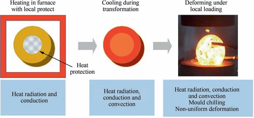
Fig. 1 Whole process of titanium disc formation under heating, cooling and deforming.
(a) Heating in an electric furnace with local protection.The billet will be placed in an electric furnace for heating to the objective temperature, and then both heat radiation and conduction should be considered. During this process, the upper and bottom surfaces of the billet will be covered with asbestos to reject heat radiation, which is for the gradient temperature distribution.
(b) Cooling during the transformation of the billet from the furnace to loading platform. The heated billet will be transferred to the loading platform, during which the billet will lose heat via dissipation.
(c) Chilling by the contact with the cold mold. The contact of the elevated billet with the cold mold will lead to a rapid temperature reduction via heat conduction and heat radiation.
(d) Deforming under the action of mold. Gradient temperature distribution allows distinct flow of materials resulting in deformation distribution, in return affecting temperature distribution.
The whole process involves heat radiation, conduction and convection, mold chilling and non-uniform deformation.Therefore, great challenges are faced to the whole-process modeling, and thus to the control of GDTD.
2.2. Test approaches
To verify the reliability of the model,some tests(heating,cooling and deforming) were carried out on the scale-down samples. For the tests of heating and cooling, samples are designed as shown in Fig. 2 with several sizes of∅40 mm×21 mm, ∅84 mm×20 mm, ∅84 mm×30 mm,∅84 mm×40 mm and ∅84 mm×50 mm. Three drill holes were made at three positions, i.e. the rim, the middle and the center, for the embedding of thermocouples. Therefore, the measured temperature by the three thermocouples can be treated as the temperatures at the rim,middle and center,and thus temperature gradient can be obtained. Twenty heating tests have been carried out:(a)putting thermocouples into the three holes; (b) covering the upper and bottom surfaces of the sample with asbestos; (c) placing the sample into a furnace, the temperature of which is set at 500, 700, 900°C and 1100°C,respective; (d) a temperature measurement instrument HPDJ8X25 was adopted to receive and read the information of thermocouples.
In addition, isothermal compression tests were carried out with the Gleeble-3500 machine. The size of the sample is∅8 mm×12 mm and the deformation temperatures are 800,900, 1000, 1050°C and 1200°C, the strain rates at 0.001,0.01,0.1 s-1and 1 s-1.The strain rates adopted tends to maintain a quasi-static deformation process,while the temperatures allow the deformation under and beyond the phase transformation point (1046°C). 20 tests have been performed, during which the samples are heated at a rate of 20°C/min and kept for 5 min and then compressed for 70%height reduction.The data obtained were used for the establishment of constitutive relations and the verification of deformation model.
2.3. Material

Fig. 2 Prototype with the sizes of ∅40 mm×21 mm and ∅84 mm×20 mm for heating and cooling tests.

Table 1 Chemical composition of IMI834 alloy.
The material used in this work is the IMI834 titanium alloy,the composition of which is shown in Table 1.The phase transformation point of the material is 1046°C and the density is 4560 kg/m3. The microstructure as received is shown in Fig. 3, from which the equiaxed α phase among the transformed β matrix can be easily found. The thermal diffusion coefficient α and specific heat capacity c of the material at different temperatures are measured by the STC449C laser thermal conductivity meter. Data at every 100°C from the room temperature to 1100°C are obtained and listed in Table 2.
3. Through-process modeling of heating, cooling and deforming by considering couple of multi-fields
3.1. General approach for modeling
The proposed approach for multi-fields coupled modeling, as shown in Fig.4,includes three stages:heating process,cooling process and deforming process.They were modeled separately at first and then were coupled via up-to-down information transformation, which will be conducted on both ANSYS and ABAQUS. The details will be discussed in following subsections. Before the start of multi-fields coupled modeling, the geometry of the billet should be created.
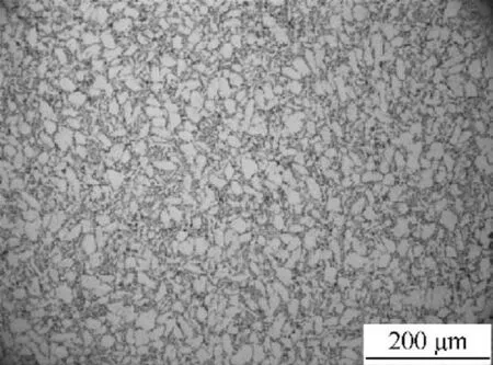
Fig. 3 Microstructure of IMI834 alloy as received.

Table 2 Material parameters of α, c, λ.
3.2. Geometry and boundary conditions
The geometries of the billet are tailored, as shown in Fig. 5, a quarter of which was created here for saving CPU time by considering its geometric symmetry. The angles θ between the slope and the top of the three billet profiles are set as 90°,127°and 135°, respectively. The larger height of its center will allow larger deformation in the center, while small deformation in the rim during the deforming process, which is for achieving the non-uniform deformation distribution. In addition, the larger height with smaller diameter helps achieve lower temperature in the center during heating process, which is for non-uniform temperature distribution.
The billet was meshed with three-dimensional thermal analysis elements(SOLID70)in ANSYS and hexahedral eight-node thermal-mechanical coupling element(C3D8RT)in ABAQUS.To balance computational efficiency and mesh quality, the geometry was artificially divided into two parts(namely,center and rim) and meshed separately, and then the two parts were bonded by Boolean operation,as shown in Fig.6.
With the geometry, thermal boundary conditions were set as:(a)the initial temperature of the billet and the surrounding temperature are set at 25°C; (b) the furnace temperature as a constant can be set. There exists heat exchange on all exposed surfaces of the billet.
3.3. Modeling of heating and cooling processes
3.3.1. Application of thermal loads
During the heating process,heat convection and heat radiation between the billet and the furnace or the surrounding are treated as two heat resources. However, just one heat resource is allowed to be applied to the thermal element during modeling with ANSYS.To solve this problem,an additional surface that is to apply heat radiation was created to cover the billet surface that is to apply heat convection.To this end,a reference point is created at 200 mm from the billet and is assigned with the furnace temperature. The surface added is meshed with the three-dimensional surface effect elements (SURF152), as shown in Fig. 7. By doing this, both heat radiation and heat convection are applied. Furthermore, heat conduction from surface to interior occurs when the surface temperature increases. During this process the nonlinear thermal parameters of the material are required.
Before the start of cooling process,the above heat loads are removed and then the heat transfer coefficient h and the surrounding temperature T are reset to consider the natural convection with air.The temperature of the billet is inherited from that at the end of heating process.The cooling process will last for 30 s.
3.3.2. Determination of material thermal parameters
(1) Thermal diffusion coefficient, specific heat capacity and conductivity coefficient Thermal parameters of the material will change with temperature during the heating and cooling processes. Thermal conductivity coefficient λ can be determined via
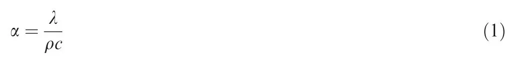

Fig. 4 Overall approach of the modeling process.

Fig. 5 Tailored profiles of billet with angle between slope and top.
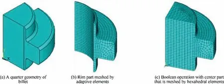
Fig. 6 Part meshing approach.
Fig. 7 Surface effective element.
where,the density of the material is 4560 kg/m3,and the phase transition point is 1055°C.
(2) Heat transfer coefficient
Except for the above parameters,heat transfer coefficient h is the most critical.However,h varies with the sample temperature, the temperature difference between the sample and the furnace, and the sample size. To quantify the heat transfer coefficient, several equations are created by fitting the experimental results. For this fitting, a trial h is used in the model to predict temperature which will be compared with the experimental ones, which will be repeated for several times until a suitable h is determined.
The relations of h with the temperature difference between the sample and surrounding (ΔT) are shown in Fig. 8(a), with the surrounding temperature (T) and sample size fixed. It is found that in the heating process h increases with T but decreases with ΔT.The relations at different T can be given as:
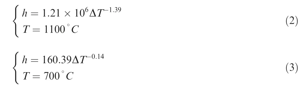
Similarly, the relations of h with the sample size (denoted by the surface area S) with T=1100°C and ΔT=550°C or 800°C are shown in Fig. 8(b). It can be found that h decreases with S and the decreasing rate slows down with increasing S. The relations at different ΔT can be given as:

Taking the above relations in hand, the heat transfer coefficient h is re-calculated every 100 seconds during the heating process.In addition,h is set at 30 W/(m2˙sK)in the cooling process. During the simulation, the analysis type is defined as transient analysis, and the full Newton-Rahpson method is used.The temperature at billet rim is taken as an index to verify the reliability of Eqs. (2)-(5). Agreement between the simulated and experimental results can be found in Fig. 9,which indicates the above thermal parameters were correctly determined.
3.3.3. Verification of the heating-cooling model
Taking a sample with the size of ∅84 mm×20 mm, and setting the initial temperature to 25°C and the heating temperature to 1100°C, heating for 150 s and cooling in air for 30 s,the verification of the heating-cooling model has been carried out. Temperatures at the rim and the center of the sample are selected,the comparison of which with experimental results are shown in Fig. 10. It can be found that the maximal difference of 35°C (the maximum deviation is 7.5%) in the heating process occurs in the final stage of heating. This result indicates the heating-cooling model is reliable.
3.4. Modeling of the deforming process
After the heating and cooling process, a gradient temperature field is obtained, which will be transferred to the model established in ABAQUS(11700 the hexahedral eight-node thermalmechanical coupling elements, C3D8RT). After the transformation, the thermal-mechanical coupled simulation will be carried out.The gradient temperature field is taken as the predefined field, and the dynamic, temp-displacement thermalmechanical coupling calculation is adopted for thermalmechanical coupling analysis. For the thermal-mechanical coupling analysis, high-temperature constitutive relations are extremely crucial.

Fig. 8 Changing rule of convective heat transfer coefficient.

Fig. 9 Comparison of rim temperature of experiment and simulation under different furnace temperature.

Fig. 10 Comparison of temperature of a sample between experiments and simulations.
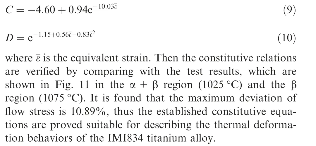
3.4.1. Constitutive relations

The Arrhenius-type constitutive frame is used to model the heat-sensitive, rate-dependent constitutive relation of the IMI834 titanium alloy, which is written as:where the coefficients C and D are functions of the equivalent strain.By fitting the experimental stress-strain results,the coefficients are determined as follow20:
In the α+β two-phase region:
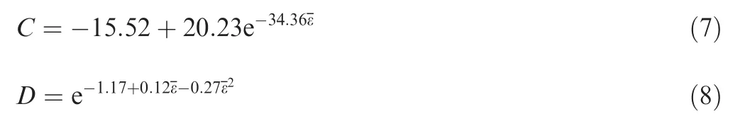
In the β single-phase region:
3.4.2. Verification of the deformation model
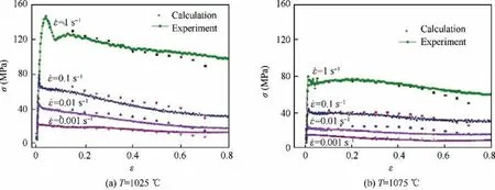
Fig. 11 Comparison of stress between calculation and experiment of IMI834 alloy at different temperature.
With the constitutive relations established above,the deformation model is created by dealing with some technical problems such as contact, friction, loading, and so on, which are common issues for almost modeling researchers and thus are omitted here to shorten the length of this work.Then this model is verified at the aspect of stress-strain response with the sample’s geometry of ∅12 mm×8 mm and isothermal condition.Deformation is done at the temperatures below (850°C) and beyond (1150°C) the phase transition point, with the strain rates of 0.01 s-1for 70%reduction and 0.1 s-1for 65%reduction, respectively. The stress-strain curves are compared as shown in Fig. 12. The maximum deviations are found as 13 MPa (4.3%) in Fig. 12(a) and 3 MPa (10%) in Fig. 12(b),respectively. It indicates the reliability of the deformation model.
After the verification, the temperature field after heating process and cooling process was assigned to the deformation model, and heat transformation (heat conduction, radiation,and convection) is then calculated during the deforming process. As the results, the whole-process model of heating, cooling and deforming has been established. With this wholeprocess model, some rules of the distributions of temperature and deformation have been studied.
4. Results and analysis
4.1. Effects of parameters during heating and cooling processes
4.1.1. Effect of heating surface
In order to get a gradient temperature distribution,three types of heating surface are designed as shown in Fig. 13. The red part indicates heating surface and the blue surface, which will not be heated,is protected with asbestos.As shown in Fig.13,for Type-I,all surfaces except for the top and bottom surfaces are heated;for Type-II,heating just on the rim surface and for Type-III, heating just on the lateral side of the rim. The furnace temperature is 1100°C,and the heating process will finish when the billet rim reaches the furnace temperature, and then the cooling process starts and lasts for 30 s.
The temperature distribution of the billet is shown in Fig. 14 after heating process and after cooling process. For Type-I,the temperature of the rim reaches 1092°C when heating for 1000 s, at this time, there is 50°C higher than the center. Moreover, the banded-distributed temperature shows evident temperature gradient after heating. For Type-II, the temperature of the rim is 80°C higher than that of the center when heating for 1400 s, and the gradient exhibits an inwardconvex distribution, which means uneven temperature distribution along the axial direction. For Type-III, temperature gradient seems not obvious. It can be attributed to the long enough time of heating (3000 s) for the rim reaching the specified temperature.With the long heating time,heat conduction from the rim to the center plays a significant role.
With the temperature distribution after heating, the billet undergoes cooling. However, the temperature gradient seems not obvious even a revised-gradient(higher at center but lower at rim)appears after cooling as show in Fig.14.That is to say the heating surface approaches cannot dominate the temperature gradient and thus other methods should also be applied.In the light of the good temperature gradient after heating,Type-I approach is adopted for further study.

Fig. 12 Comparison of stress-strain responses of sample compressed at different temperature obtained from simulations and experiments.

Fig. 13 Illustration of three types heating surface.
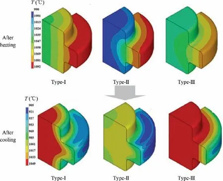
Fig. 14 Gradient temperature distribution of billet after heating and after cooling with different heating approaches.
4.1.2. Effect of billet profile
By adopting the Type-I approach for heating,the effect of billet profile is also investigated.The three profiles of the billet in Fig. 5 are adopted here. The temperature distributions of the billet after heating and after cooling are shown in Fig.15.Similarly, the temperature of the furnace is 1100°C, the three billets are heated for 880 s, 950 s and 1000 s, respectively, for reaching the same rim temperature at 1085°C, and then followed by 30 s cooling in air.From Fig.15,it can be found that an obvious temperature gradient is obtained after both heating and cooling with the latter two profiles (127° and 135°), and the maximal temperature differences between the center and the rim are 110°C and 119°C, respectively, after heating.However,only the second profile maintains temperature gradient after cooling. That is to say the second profile should be better for the purpose of gradient temperature distribution.

Fig. 15 Gradient temperature distribution of the billet after heating and after cooling with different profiles of billet.
4.1.3. Effect of furnace temperature
In addition, the effect of furnace temperature is also studied.To this end, the furnace temperature is set at 1100, 1300°C and 1500°C, respectively, with Type-I approach. The heating process lasts until the temperature of the rim is close to the furnace temperature.Therefore,the heating takes 900 s,400 s and 200 s,respectively at these three furnace temperatures,then the cooling process lasts for 30 s.
The temperature fields distribution after heating and after cooling are shown in Fig. 16. When the heating temperature is 1300°C and 1500°C, the maximum temperature difference between the rim and the center is 300°C and 800°C respectively; when the heating temperature is 1100°C, the temperature exhibits uniform. It can be explained as that the higher the furnace temperature is,the faster the rim temperature rises,and thus the more obvious the temperature gradient is. After cooling, the temperature gradient reverses when the furnace temperature is 1100°C, of the center after cooling is higher than that of the rim.On the contrary,the temperature gradient is kept when the furnace temperatures are 1300°C and 1500°C.Furthermore,the gradient turns large with the higher furnace temperature. However, the extremely high furnace temperature(1500°C)will result in a large temperature difference between the rim and the center. Too high temperature of the rim will cause the over-burning of the material,at the same time, the center temperature far below the phase transition point will lead to deformation difficulty.As the result,the furnace temperatures at 1300°C is prior in this work.
4.2. Effects of parameters during the deforming process
4.2.1. Effect of mold chilling
When the heated billet contacts with the mold during the forming process, mold chilling becomes inevitable because of the lower temperature of the mold.In this work,H13 steel is used for the mold and thus 500°C is set with the mold,and the heat transfer coefficient is set as 50 kW(m2°C). The initial temperature of the billet before deformation is shown in Fig. 17.
To illustrate the effect of mold chilling, a comparison has been carried out between the situation with mold chilling and that without mold chilling. With a strain rate of 0.1 s-1,the temperature distribution during the deforming process is shown in Fig. 18. Two points at different deformation stages(deforming for 3 s (Fig. 18(a)-(b)) and 10.5 s (Fig. 18(c)-(d))when the deformation finishes) have been chosen to do the comparison. The results in Fig. 18(a) and (c) are calculated without mold chilling, while those in Fig. 18(b) and (d) are with mold chilling.

Fig. 16 Gradient temperature distribution of billet after heating and after cooling with different furnace temperature.
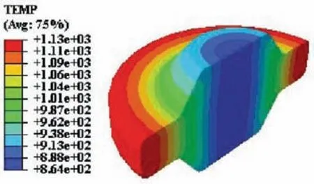
Fig. 17 Temperature distribution of billet before deformation.
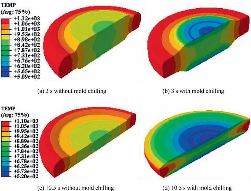
Fig. 18 Temperature distribution of the billet during the deforming process.
It can be found from Fig.18 that without mold chilling the temperature decreases from the rim to the center which forms a ring-like gradient;after deformation the temperature at the rim decreases to 1100°C and that at the center increases slightly to 874°C,and thus the difference between the rim and the center keeps about 200°C.What is distinct with mold chilling is that the temperature at the contact area drops down sharply (just larger than the temperature of the mold);the temperature field at the center shows funnel-shaped; at the final stage of the deformation the mold contacts with the billet rim, which results in temperature reduce of the rim, thus the higher temperature inside the billet and lower at the surface, and then a convex ladder-shaped temperature field is obtained. At the time of deformation finishing, the temperature reaches 1090°C at the rim while 850°C at the center keeping the temperature difference almost unchanged.
However, more obvious effect has been done on stress and strain responses by mold chilling with the comparison to that on temperature. The stress and strain distributions after deforming are shown in Fig.19.Much larger stress and larger stress area can be found with mold chilling (Fig. 19(a)-(b)).The maximum stress (939 MPa) concentrates at the surface of the center with mold chilling, while it (269 MPa) is at the middle center of the billet without mold chilling. On the contrary,the relative smaller strain(4.55)was achieved with mold chilling while the strain of 5.83 was achieved without mold chilling. In addition, the dead zone (almost no strain at the center) is much larger with mold chilling than that without mold chilling.As the result,a gradual gradient of deformation can be obtained with mold chilling.

Fig. 19 Stress and strain distributions of billet after deforming.
It is worth mentioning that all deformation results below are obtained by considering mold chilling to reflect the actual situation.
4.2.2. Effect of billet profile
Again, the three profiles of billet in Fig. 5 are adopted here to do researches on the effect of billet shape on the distributions of temperature and deformation during the deforming process.All conditions are the same as in Section 4.2.1. The deformation was carried out to obtain a disc with the same height.
The temperature distribution after deformation is shown in Fig. 20. Gradient temperature distribution can be found in all of the three deformed discs, and maintains about 250° difference from the rim to the center for the first two cases. With the one of 127°, the surface temperature at the rim is much higher than that of the other two. It may be attributed to that the billet shape with 127° angle help keep a good temperature distribution due to heat generation during deformation. With the one of 135°, the rim contacts with the mold too early,and thus the mold chilling effect exhibits significant. As the result, the temperature difference between the rim and center comes down to 160°C, and also the overall temperature of the disc decreases.
The equivalent plastic strain distribution is in the same manner, as shown in Fig. 21. It exhibits a X-shape at the cross-section,while very small strain can be found at the upper and lower surfaces of the disc center. This is attributed to the dead zone during forging deformation and the much lower temperature at the center surface caused by mold chilling.The gradient distributed strain,namely larger strain at the center gradually decreasing to lower strain at the rim, has been obtained, especially for the first two cases. With the angle of 135°, the billet height is smaller, and thus the deformation degree is small.Together with the much obvious mold chilling effect, the stress concentrated at the center increases and thus the dead zone disappears.
Based on the analysis above, the profile angle of 127° is proved as more suitable one for achieving good GDTD in this work.
4.2.3. Effect of deformation rate
Deformation rate is a very important parameter to affect the deformation process. Therefore, the loading rate of the mold is set as 0.01 s-1, 0.05 s-1and 0.1 s-1respectively, to study the effect of deformation rate on the distributions of temperature and deformation.The results can be found in Fig.22.The gradient distribution of temperature can be found under all of the rates,while the gradient ascends with the increasing rate.It can be attributed to the heat generation during deformation and the relative shorter loading time under a larger rate.
The equivalent plastic strain distributions of the deformed discs are illustrated in Fig. 23. The similar strain gradient can be found under all of the rates. With the increase of rate,the gradient from the center to the rim seems much more gradual, which will benefit further control of microstructure and performance.
From the analysis above, the reduction of the loading rate leads to a prolonged deformation time, and thus the cooling effect becomes more obvious. As the results, the temperature falls and then the material flow is affected so that the strain decreases. Therefore, a larger deformation rate is needed to obtain better distributions of temperature and deformation.

Fig. 20 Temperature distribution of the deformed discs from the billet with different profile angles.

Fig. 21 Strain distribution of deformed discs from billet with different profiles angles.

Fig. 22 Temperature distribution of the deformed discs with different loading rates.

Fig. 23 Strain distribution of the deformed discs with different loading rates.
5. Discussions As analyzed in Section 4, GDTD of a titanium disc can be obtained by adjusting several key parameters including the heating surface, furnace temperature, billet profile, mold temperature and deformation rate. Moreover, suitable values are also suggested. These results will help achieve good GDTD in practice.
As known to all, microstructure evolution of the titanium alloy is extremely sensitive to temperature and deformation.Therefore, the higher temperature at the rim, particularly beyond the phase transformation point,will lead to rapid grain coarsening in the β single-phase region. Consequently, a microstructure with coarse β grains, i.e., Widmannstatten structure, can be obtained which will exhibit high resistance to creep and crack. At the same time, the relative lower temperature at the center (in the α+β two-phase region) allows some amount of the α phase. In addition, larger strain at the center promotes the dynamic recrystallization which will refine the grains and guarantee an equiaxed structure. The equiaxed microstructure will exhibit good ductility, high strength and low cycle fatigue strength of the center. The expected microstructure and the corresponding performance are the right goal of the existing technologies as mentioned in Introduction section. What is more, the goal is realized directly by the common forging technology,and also the gradual changed temperature and deformation between the center and the rim maintain a gradual changed,not sharply altering,performance of the formed product. This shows the advantage of the proposed approach in this work.
However,further work should be done on the experimental verification of the microstructure evolution by utilizing the proposed approach. This work is ongoing and is expected to come out in the near future.
6. Conclusions
Aiming at GDTD of a titanium disc, a whole-process model has been established in this work. With this model, the effects of several key parameters on GDTD and the related conclusions have been obtained:
(1) Type-I heating approach (all surfaces except for the upper and bottom surfaces are heated) helps achieve a good gradient temperature distribution during heating.However, the gradient will disappear unless the billet profile is tailored. The billet profile with the angle of 127° is believed as the better one.
(2) Temperature gradient increases with the increase of furnace temperature, however, too high furnace temperature will result in the over-burning of the material, at the same time, the center temperature far below the phase transition point will lead to deformation difficulty.Thus, the furnace temperatures at 1300°C is better.
(3) GDTD becomes more obvious with the increasing loading rate, while 0.1 s-1are suggested for good gradient distributions of temperature and deformation for the reason of the quasi-static deformation process.
Acknowledgement
The authors would like to thank the National Natural Science Foundation of China (No.51675433)and the Natural Science Foundation for Distinguished Young Scholars of Shaanxi Province (No. 2019JC-09) for financial supports given to this research.
杂志排行

CHINESE JOURNAL OF AERONAUTICS的其它文章
- Design and experimental study of a new flapping wing rotor micro aerial vehicle
- CFD/CSD-based flutter prediction method for experimental models in a transonic wind tunnel with porous wall
- Prediction of pilot workload in helicopter landing after one engine failure
- Study of riblet drag reduction for an infinite span wing with different sweep angles
- Modulation of driving signals in flow control over an airfoil with synthetic jet
- Strong interactions of incident shock wave with boundary layer along compression corner