Design and experimental study of a new flapping wing rotor micro aerial vehicle
2020-02-24XinDONGDaochunLIJinwuXIANGZiyuWANG
Xin DONG, Daochun LI, Jinwu XIANG, Ziyu WANG
School of Aeronautic Science and Engineering, Beihang University, Beijing 100083, China
KEYWORDS Attitude estimation;Flapping wing rotor;Flight control;Flight tests;Micro aerial vehicle (MAV)
Abstract A three-wing Flapping Wing Rotor Micro Aerial Vehicle (FWR-MAV) which can perform controlled flight is introduced and an experimental study on this vehicle is presented. A mechanically driven flapping rotary mechanism is designed to drive the three flapping wings and generate lift,and control mechanisms are designed to control the pose of the FWR-MAV. A flight control board for attitude control with robust onboard attitude estimation and a control algorithm is also developed to perform stable hovering flight and forward flight. A series of flight tests was conducted, with hovering flight and forward flight tests performed to optimize the control parameters and assess the performance of the FWR-MAV.The hovering flight test shows the ability of the FWR-MAV to counteract the moment generated by rotary motion and maintain the attitude of the FWR-MAV in space; the experiment of forward flight shows that the FWR-MAV can track the desired attitude.
1. Introduction
Since the concept of Micro Aerial Vehicles(MAVs)was introduced about 30 years ago, research into MAVs has increased significantly. The U.S. Defense Advanced Research Projects Agency (DARPA) conducted a three-year MAV program to create an aerial vehicle less than 15 cm for missions of military surveillance and reconnaissance.1In recent years, many tasks require Vertical Takeoff and Landing (VTOL) and hovering of MAVs in a given space;thus,the MAVs with configurations of rotary and flapping wings have drawn considerable attention. The development of the Microcontroller Unit (MCU)and control algorithms promotes the design of numerous types of rotary-wing MAVs. For example, the ProxDynamics of Norway has developed such an MAV, ‘Black Hornet’, the smallest commercial unmanned aircraft system with a weight of 16 g (UAS),2and this UAS is now in service in the British Army. However, the weight of this UAS and the complexity of its structure are increased by the tail rotor or other devices which are necessary for single rotor aircraft to balance the torquer generated by wing rotation.
Because of the high aerodynamic efficiency of flapping wings at a low Reynolds number,birds and flying insects have shown outstanding flight performance.Abundant research has been carried out with the development of flapping wing MAVs.3,4˙Zbikowski et al. developed an insect-like flapping wing mechanism using a double spherical Scotch yoke to mimic insect flapping wing motion.5,6A Titanium-alloy Micro-Electro-Mechanical System (MEMS) wing7and Poly Vinylidene Fluoride (PVDF) sensors8were applied to design the flapping wing MAV.Tsai and Fu obtained the average lift of a planar membrane wing through initial 3D aerodynamic calculation, and then made an ultra-light small flapping MAV of a gross weight less than the average lift.9Yang et al.developed a flapping MAV using electrical-discharge wire cutting technique which reduces the body mass of the flapping MAV from 11 to 5.9 g, the flight endurance of this MAV was increased to 6 min 7 s.10In 2010, Ulrich et al. developed a single-wing-rotating MAV to emulate natural samara.11,12Keennon et al. developed a Nano Humming bird which can perform controlled hovering flight with the use of its two flapping wings.13Ma et al. built an 80 mg flapping-wing robot modeled on the morphology of flies and demonstrated unconstrained stable hovering and basic controlled flights.14Wagter et al. designed DelFly ‘‘Explorer”, a 20 g flapping-wing MAV with a 0.98 g autopilot and a 4 g onboard stereo vision system which can perform autonomous flight.15Phan et al.developed a 21 g tailless flapping wing MAV,with its control mechanism integrated with three sub-micro servos to realize attitude control.16Kara´sek et al. built DelFly Nimble, a tailless flapping wing MAV which can fly in any direction.17
Integrating the advantages of flapping and rotary wings,Guo et al.18proposed an alternative concept, Flapping Wing Rotor (FWR), in which wings capable of flapping vertically are installed uniformly around the central axis with the same attack angle.The momentum produced by the flapping motion thrust drives the wings to rotate around the central axis so that both the flapping motion and the rotation of the wings produce the lift required to overcome the vehicle weight for VTOL and hovering. After the FWR configuration was put forward,a number of research programs on this new concept have carried out experimental and theoretical analyses. Lal Kummari et al. developed an FWR model using piezoelectric materials for power, and by measuring its lift demonstrated that this design was a practicable configuration for MAVs.19,20Wu et al. designed an electromechanical drive model for FWRs and obtained similar conclusions via a series of experiments.21Meanwhile, a series of numerical methods was also applied to the development of FWRs. Using the finite element method,Guo et al. performed kinetic analyses for piezoelectrically driven FWRs.22Wu et al. used Computational Fluid Dynamics(CFD)method to analyze the unsteady aerodynamic behavior of such a layout at a low Reynolds number.23Wu et al. also compared aerodynamic power efficiencies of an FWR,rotating wing, and flapping wing.24Guo et al. investigated the aerodynamic efficiency of bioinspired FWR kinematics and developed a flyable micro FWR25-27with electric power supplied through wires. In 2017, RotorBee, developed by Beihang University, China, became the world’s first FWR to achieve vertical take-off with power.28Due to the absence of attitude and altitude control components and the corresponding automatic or remote-control system, the RotorBee would sometimes shake, and even fall, during flight tests; therefore,attitude control components must be designed for controlled flight of the FWR-MAV.
This paper presents a three-wing mechanically driven FWR-MAV with a group of control flips,and with a coin size flight control board with onboard attitude estimation and a control algorithm to perform controlled flight. A series of flight tests is introduced to demonstrate the feasibility of this MAV.
2. Overall design
To achieve controlled flight, a three-wing FWR-MAV with control surfaces was designed, as shown in Fig. 1. This FWR-MAV consists of three parts: the lift generating system,attitude control mechanism and avionic system. The upper part of FWR-MAV is the lift generating system, including flapping wings and driving mechanism. There are three flapping wings which can rotate freely around the center during flapping.The wings are composed of a wing beam made of carbon fiber composites and polyethylene membranes. The attitude control mechanism is designed to control the attitude of the FWR-MAV. The weights of the components are listed in Table 1.The body axis of the FWR-MAV is fixed on the body,with the positive direction being point forward,pointing to the right, and the z axis being point down.
2.1. Driving mechanism
The upper part of the FWR-MAV is the lift generating mechanism, composed of wings and their driving mechanism consisting of brushless motor, gears and transmission (Fig. 2).
Flapping motion is the primary movement for FWRs, and an appropriate drive form is essential for achieving flapping motion. The rotary speed of a motor is reduced first by the gear and then by the slide bar connected on the transmission rod, transforming the rotary motion of the crank to the reciprocating motion of the Support 1.The wings are connected to their driving mechanism, which transforms the linear motion of the upper support into the flapping motion of the wings.The gear ratio of the motor and crank is 26:1 which transform the high frequency rotary of the motor to low frequency of the motion of wings, and the design flapping frequency of the wings is about 20 Hz.

Fig. 1 FWR platform.

Table 1 Components of FWR-MAV.
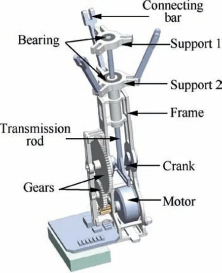
Fig. 2 Driving mechanism of FWR-MAV.
The flapping rotary mechanism of this aircraft is a typical four-bar linkage mechanism, as shown in Fig. 3. Support 1 is fixed at the top of the reciprocating transmission rod, while Support 2 is fixed at the top of the sleeve. The wings are connected to the upper support at their roots.One end of the connecting bar is affixed to the support, with the other end connected to the wings near the wing root. Such a mechanism allows the flapping motion and rotation around the transmission rod to occur at the same time.In this mechanism,the flapping angle of the wings and the position of the end of upstroke or downstroke can be controlled by adjusting the length of each rod of the mechanism.
2.2. Stabilizers and control surfaces
The attitude control mechanism consists of stabilizers and control surfaces,as shown in Fig.4.The stabilizers are designed to improve the stability of the FWR-MAV, composed of a carbon fiber frame and a polythene covering. The control surfaces, composed of an elevator and a pair of differential ailerons, are designed to control the attitude of the MAV.The pitching moment is provided by the elevator deflection.The negative moment in y axis is generated by the positive deflection angle of the elevator, which drives the FWR-MAV to pitch down and fly forward.The roll angle and orientations of the FWR-MAV are controlled by the deflection of the differential ailerons. Each rudder is driven by a servo.

Fig. 3 Drive mechanism of FWR-MAV.

Fig. 4 Stabilizers and rudders.
3. Flight control system
3.1. Flight control board
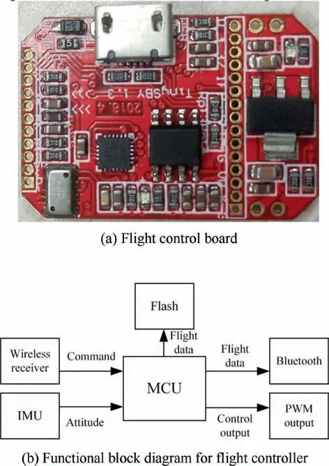
Fig. 5 Flight control board.
To address the limited space and weight available for attitude control devices, a light-weight coin-sized flight control board(2.5 g) is designed to control the attitude of the FWR-MAV,as shown in Fig. 5(a). The autopilot board contains an STM32F405 MCU for onboard processing of sensor signals and the MPU9250 9-axis IMU with accelerometers, gyroscopes and magnetometers used for attitude estimation. The control board has 6-channel control signal output to drive the motor to generate the flapping motion of the wings or to drive the deflection angle to maintain the desired attitude.There are 2 MB flash memories on the board to save sensor outputs, attitude state, and other information for analysis.The wireless receiver is used to receive the control signal send by the remote controller,or communicate with the PC for initializing flight and retrieving the data stored in the flash memory. The functional block diagram of the board is shown in Fig. 5(b).
3.2. Attitude angle
The body axis of the FWR-MAV (Fig. 1) is defined as being Forward-Right-Down, and the world axis is North-East-Down (NED). The attitude is represented by two different forms:
(1) Euler angles:Three different angles describe the attitude of the FWR-MAV, which are roll(φ), pitch(θ), and yaw(φ). The 1-2-3 rotation sequence (Roll-Pitch-Yaw) is used to define the definition of Euler angles. The yaw angle is the angle between the projection of the body axis xbin the horizon plane and the earth’s axis. The pitch angle is the angle between the body axis xband the horizon plane. The roll angle is the angle between the body axis yband the horizon plane.
(2) Quaternion: It is generally represented byq0+q1i+q2j+q3k, where q0, q1, q2and q3are real numbers, and i, j, k are the fundamental quaternion units. The Euler angle is used to describe the attitude during data fusion.Quaternion has a low cost in dealing with the coordinate transformation. Eq. indicates the relationship between the Euler angle and quaternion.

The values of c1, c2, c3, s1, s2, s3is calculated by:

As can be seen from Eq.(2),a great deal of angle conversation and coordinate transformation exist, which means that the trigonometric function will be used frequently. Due to the limited calculating ability of the micro-controller, the Coordinate Rotation Digital Computer (CORDIC) algorithm is used as a library.
The attitude angle can be obtained by the angular velocity in the body axis through:

3.3. Attitude estimation and control
The Euler angle is calculated based on the output of the accelerometer and on the assumption that the accelerometer is only influenced by the gravitational force,which is obviously unpractical. For accurate onboard state estimation, the accelerometer output should be filtered to lower its noise,and the data from other sensors, such as gyroscope, should also be considered.
The accelerometer data are disturbed by two factors: the vibration induced by the motor and the wings’ flapping. The accelerometer output is first filtered by a low-pass filter to remove the noise created by the high-speed rotation of the motor, and then a moving average filter is included to reduce the noise caused by the flapping motion.
3.3.1. Attitude estimation
During free flight, the attitude of the MAV can be obtained with the output of the accelerometer, as shown in:
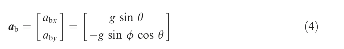
where abis the acceleration of the MAV in the body frame,which can be measured by the accelerometer, g is the acceleration of gravity in the world frame, and the roll and pitch angle can be obtained through:

The output of the accelerometer is disturbed badly by the mechanical vibration of the MAV, so the output of the gyroscope is used to improve estimation accuracy. The first-order complementary filter is used to estimate the roll and pitch angle integrated by the data of gyroscope and the attitude generated by the accelerometer data, and the orientations of FWR-MAV are estimated by fusing the data of gyroscope in the z axis and the data of magnetometer. The equation of the complementary filter for the pitch angle as shown in:

3.3.2. Attitude control
The desired attitude is given by the remoter.Then the attitude error is calculated by Eq.(7),where dais the desired attitude,rais the estimated attitude of the MAV, and eais the attitude error.

During the flight,the attitude of the FWR-MAV is actively controlled by adjusting the deflection angle of the rudders,and the elevator is used for longitudinal attitude control and differential ailerons for lateral and heading control.The closed loop controller is designed to stabilize the attitude of the FWRMAV, three Proportion-Integral-Derivative (PID) controllers are used to calculate the control outputs of three attitude angles (roll, pitch and yaw), calculated by:

For longitudinal control, the control output of the pitch angle is used to control the flap angle of the elevator, while for latitudinal control, the flap angle of each differential aileron is determined by the control outputs of both the roll and yaw, so the actual flap angle of each differential aileron is calculated by Eq. (9), where uroll,upitch,urollare the control output of three attitude angles.

4. Flight tests
The ability to hover and fly forward at a given attitude angle is important for the MAV, and vital for an MAV to perform autonomous flight. To evaluate the performance of the FWR-MAV designed on hovering and forward flight, a series of flight experiments was designed.
The flight experiment was conducted to tune the gain of the controller and improve the stability of the attitude control.The gains of the PID controller in three attitude angles are shown in Table 2.
The difference of the three gain sets list above lies in that the Kpof the PID controller in the yaw angle is 9 times larger than that in the roll angle controller. Moreover, the Kpof all the three controllers is larger than the value of Kd.
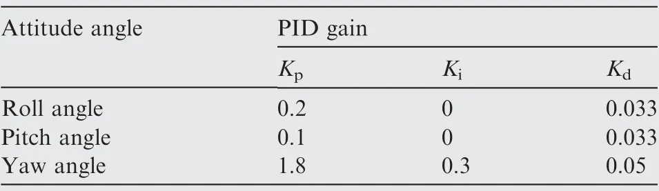
Table 2 Gains of PID controller at different attitude angles.
4.1. Hovering flight
In the hovering flight, the FWR-MAV was controlled by the closed loops to stabilize the attitude, with the pitch angle controlled by the elevator,the roll angle by the deflection of differential aileron in the same direction, and the yaw angle by the deflection of the differential aileron in the opposite angle.The reference angle of the three attitude angles was 0°. The positive deflection angle of each rudder is shown in Fig. 6(a),where the positive deflection angle of two differential ailerons was defined in the opposite direction. The differential ailerons deflect symmetrically to balance the wing torquer. The deflection of the rudders during the hovering flight is shown in Fig.6(b).
As can be seen from Fig.6(a)that the deflection of each differential aileron is in the opposite side, which can generate a rotary moment to cancel the moment created by the rotary motion of the wings. The elevator deflects around zero degree to balance the pitch angle. Fig. 7 shows the onboard estimate of the roll, pitch and yaw angles during the hover flight.
The control input of each attitude angle was zero.The attitude of FWR-MAV vibrates around the desired angle (0°),which means that the FWR-MAV can hold its attitude in the space with the control input of 0° from the remoter.Fig. 8(a) shows the time history of the measured accelerated speed data of different axis of the FWR-MAV.A Fast Fourier Transform(FFT)was used to transfer the data of time history into frequency domain, with the sampling frequency being 40 Hz.Fig.8(b)shows the frequency of accel data in the x axis,with two main frequencies: 2.5 Hz and 13.67 Hz. The low frequency is the frequency of the pitching movement of the airframe, and the high frequency was induced by the motion of the wings.
The Root Mean Square Error(RMSE)of the attitude angle can evaluate the ability of the FWR-MAV to track the reference attitude angle. The RMSE of each attitude angle in the hovering flight experiment is:

The RMSE of the roll and pitch angle is relatively high,due to the vibration of the MAV induced by the flap and rotary motion of the wings. While the yaw angle is less affected by the damp of the MAV, so the FWR-MAV has good performance in holding its orientations.

Fig. 6 Deflection angle of each rudder in hovering flight.

Fig. 7 Attitude angle in hovering flight.
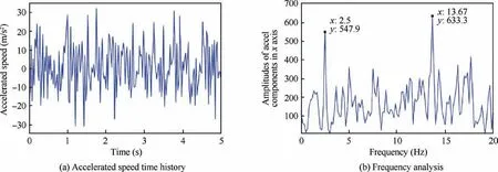
Fig. 8 Attitude angle in hovering flight.
The ability of forward flight is vital for the FWR-MAV to undertake a flight mission. In order to evaluate the flexibility of the FWR-MAV, a series of flight tests was conducted, as shown in Fig. 9. During the flight test, a reference pitch angle was given by the remoter, and the attitude angle of the FWRMAV was controlled by the flight controller to follow the desired angle.
Experimental results of the onboard attitude estimation and control in the forward flight are shown in Fig.10,in which the red line shows the desired angle that flight controller received from the remoter. The amplitude of the reference angle is 30°, and the blue line is the pitch angle of the FWRMAV measured onboard.
4.2. Forward flight
Fig.10 shows that the FWR-MAV can successfully follow the positive reference signal, which indicates good performance in forward flight. However, it is difficult for the FWR-MAV to follow the negative control signal, which means that it can hardly follow the desire attitude in backward flight. The main reason is that the mass center is not on the symmetry axis of the FWR-MAV due to the battery position. According to Fig. 10, the response time is around 120 ms. The FWRMAV overshoots when adjusting its attitude, with an overshoot of about 10° back to hovering from the forward flight,and with a significant overshoot of nearly 20° when the FWR-MAV turns into the hovering flight from the backward flight. Due to the high vibration of the flapping motions, the attitude has a great overshoot during the flight test,so the control algorithm of the FWR-MAV can be further improved.

Fig. 9 FWR-MAV in forward flight.
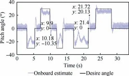
Fig. 10 Pitch angle during forward flight test.
5. Conclusions
For the first time in the literature, an FWR-MAV which can perform controlled flight has been designed.For onboard attitude estimation, the accelerometer data contains high noise due to the damp of the flapping motion, so a complementary filter was designed to estimate the attitude angle of the FWR-MAV. Three PID controllers with different gain sets was used on the attitude control.
A set of flight experiments was conducted to adjust the gains of the PID controller. The experiment of hovering flight shows that the FWR-MAV can hold its attitude with the application of the attitude controller. The accel flight data shows that the x axis has two main frequencies, with the high frequency likely induced by the wing motion and the low one likely caused by the frame vibration. No significant principal component in the y axis is found caused by the coupled motions of the differential ailerons; the accel in the z axis is mainly influenced by the high frequency motion of the wings.
The forward flight was conducted to evaluate the performance of the FWR-MAV in longitudinal flight with the reference angle being ±30°. In the forward flight experiment, the FWR-MAV shows good ability to maintain its pitch angle in the forward flight, though it also shows difficulty in holding the given pitch angle during the backward flight caused by the shifts of the gravity center of the FWR. Further optimization of the distribution of such components as flight controller and battery are needed to enhance the performance of FWRMAV designed in backward flight.
Acknowledgement
This work was supported by the National Natural Science Foundation of China (No.: 11572023).
杂志排行

CHINESE JOURNAL OF AERONAUTICS的其它文章
- CFD/CSD-based flutter prediction method for experimental models in a transonic wind tunnel with porous wall
- Prediction of pilot workload in helicopter landing after one engine failure
- Study of riblet drag reduction for an infinite span wing with different sweep angles
- Modulation of driving signals in flow control over an airfoil with synthetic jet
- Strong interactions of incident shock wave with boundary layer along compression corner
- An efficient regulation approach for tomographic reconstruction in combustion diagnostics based on TDLAS method