Simulation of multi-axis grinding considering runout based on envelope theory
2020-02-24YanJIANGQiangGUO
Yan JIANG, Qiang GUO
School of Mechanical & Power Engineering, Henan Polytechnic University, Jiaozuo 454150, China
KEYWORDS Analytic algorithm;Complex surface;Envelope theory;Multi-axis grinding;Wheel runout
Abstract As one of the most important methods for machining process with high accuracy,ultra-precision grinding is widely used in fields such as aerospace, automotive and mold, etc.Simultaneously, it is common that wheel and spindle axis do not coincide with each other due to wheel settings, machining errors and so on. This could result in the generation of wheel runout,which may reduce the machining surface’s quality. In this paper, combining this phenomenon, an analytic algorithm method for the multi-axis grinding process is introduced according to the envelope theory.After that,the accuracy of this method is verified.Two experiments are carried out on a 5-axis machining center. The artificial runout is set up and calculated utilizing the least square method.Finally,using the presented method,two examples with and without runout are introduced to illustrate the validation of the proposed model.The error due to the runout effect is also analyzed.©2020 Chinese Society of Aeronautics and Astronautics.Production and hosting by Elsevier Ltd.This is an open access article under the CC BY-NC-ND license(http://creativecommons.org/licenses/by-nc-nd/4.0/).
1. Introduction
High precision-grinding becomes more and more common in the ultra-machining process due to its elevated speed, lofty material removing rate and good surface quality.A prominent study on high-precision grinding is surface accuracy.1,5In addition, the multi-axis CNC grinding technique is a very important application.6,7
In the last few years, many researchers focused their investigations on the kinematics8and geometrical error modeling,9-11parametric interpolation,12,13efficient tool-path generation,14-20constrained feed-rate scheduling,21-23and real-time contour error estimation.24Great achievements have been made on envelope surface modeling.Chiou and Lee25got a closed-form solution of the envelope profile for general cutters undergoing a five-axis tool motion.Du,et al.26and Weinert, et al.27simplified the derivation and computation of Chiou’s work by introducing a moving frame and formulating the instantaneous swept profile.Two closed-form solutions for calculating swept surfaces of milling tools based on the moving frame method was proposed.28Siebrecht,et al.29simulated the triaxial grinding process using WC-Co cemented carbide materials, and they predicted cutting forces during grinding.Li,et al.30studied the single crystal silicon nano-grinding process using a diamond abrasive wheel based on threedimensional molecular dynamic kinematics. Krajnik, et al.31simulated the centerless grinding process,which improved efficiency. Nguyen and Butler32,33studied the grinding wheel’s surface morphology and corresponding surface’s micro-ripple.Brinksmeier,et al.34discussed the importance and necessity of conducting simulation studies on the grinding process. Due to spindle installation and bearing accuracy, there are errors in the grinding process. Therefore, Shi35discussed the workpiece runout during the centerless grinding process.He,et al.36proposed a digital method based on the point-vector envelope to calculate the wheel’s profile and simulate the envelope surface.Li and Zhu37,38presented a new approach to integrate cutter runout effect into envelope surface modeling and tool path optimization for the five-axis flank milling with a conical cutter, which can significantly reduce the geometric errors induced by runout.
Most of mentioned literatures consider workpiece runout in milling process. However, there is runout not only in milling process but also in grinding process. In this paper, we study the wheel runout in the grinding process. When the wheel is mounted on the main shaft,the wheel axis does not completely coincide with the spindle axis. additionally, it is common that the wheel’s rotating surface and the ideal one are not identical,which originates from the spindle installation and machining errors. Then, previous researches focus on the cutter or the workpiece runout during the three-axis grinding. With development of the high-precision machining technology, the demand for multi-axis grinding becomes more and more urgent. Therefore, following consideration of the wheel runout, the multi-axis grinding process is emerged. Thereby, the multi-axis grinding considering the wheel runout is studied.
2. Analytical algorithm of grinding process considering wheel runout
It is difficult to obtain the envelope surface for wheels with runout. Thus, a new analytical algorithm is established to describe the envelop surface in this paper.
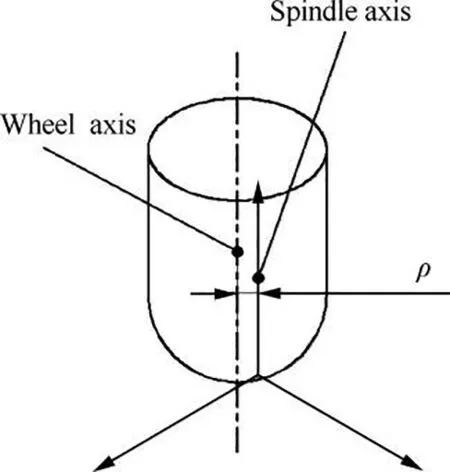
The wheel runout is created when the wheel’s axis does not correspond with the spindle axis because of installation error as shown in Fig. 1. The ideal profile of the grinding wheel is not identical with the actual worn or bearing wear wheel.This phenomenon is known as the wheel runout. There is one parameter which can define this runout,it is ρ,i.e.,the vertical distance between axes of the wheel and the spindle.
When there is no runout and wheels are not worn, the rotating bodies formed by wheels rotating about the spindle is exactly wheels themselves. Whereas, the rotating ones must be different from ideal wheels when runout exists.The rotating body participating in the grinding is a rotating body formed by the wheel’s generatrix rotating around the main shaft. On the basis of previous work39,40, the following algorithm is proposed.

Fig. 1 Wheel runout.
2.1. Establishment of sweeping surface for wheel
To correctly describe the actual rotating body,two coordinate systems are established (as shown in Fig. 2) firstly. They are Grinding Wheel Coordinate System (GWCS) OcXcYcZcand Rotating Coordinate System (RCS)OrXrYrZr.
z-axis of GWCS coincides with the wheel’s axis, z-axis in RCS coincides with the spindle’s axis.x-axes of two coordinate systems are parallel to each other originally.y-axes of both systems can be determined by the right-hand rule.
GW body can be formed by rotating a generatrix around its axis(as shown in Fig.3).A cubic B-spline curve is used to represent the grinding wheel’s generatrix, which is:

The wheel sustains wearing during the grinding process.This situation is embraced into the wheel’s generatix. This algorithm is shown in Fig. 4. The specific process can be described as:
●Dividing the wheel into N elements along the axis.
●For each element,the surface is detected using the tool measuring instrument. Supposed that M point on each element’s surface is obtained as [xk,j, yk,j, zj], j stands for the jth element and k is kth point on the jth element’s surface.j ≤N and k ≤M.
●Worn wheel is installed on the main shaft.The wheel runout exists. Runout parameter is detected previously.
●When the wheel is rotating about the spindle axis, the largest radius among those points to the spindle axis can be found, and put down the point as [xmax,j, ymax,j, zj]. Then the radius Rmax,jfor this point can be calculated using:

Fig. 2 Wheel and rotation coordinate systems.

Fig. 3 Common grinding wheel generatix.

●When fastest points on all the elements are gained, a series of new point can be constructed using the set as [0, Rmax,j,zj] or [Rmax,j, 0, zj].
●Finally, all points [0, Rmax,j,zj] or [Rmax,j, 0, zj] in each element are taken as the generatrix points of the grinding worn wheel, which can be brought into Eq. (1).
It should be noticed that there are two cases for generatix.First of all, Curve 1 is the nearest generatrix, and the farthest one is Curve 2 (shown in Fig. 5).
(a) The minimum revolving body
When Curve 1 rotates about the spindle axis,the minimum revolving body will be formed.
(b) The maximum revolving body
Curve 2 can form the maximum revolving body. It is comprehensible that the maximum revolving body can grind workpieces.
The maximum volume can be defined as follow:


Fig.4 Flow chart for calculating generatrix of wheel with wear.

Fig. 5 Computation of rotational surface about spindle axis.
According to the above analysis, it is understandable that the actual participating grinding body is no longer the grinding wheel itself when considering runout but the maximum revolving body.Based on the actual multi-axis machining kinematics theory, the actual sweeping surface of the wheel can be solved according to the envelop theory.
2.2. Solution of any point on wheel’s sweeping surface considering runout
Regardless of the multi-axis machine tool’s specific structures,the envelope sweeping surface combining with the universal five-axis machine’s kinematics is studied in this section.
The Workpiece Coordinate System (WCS) is defined as OwXwYwZw(As shown in Fig. 6). In the initial state, each corresponding axis for the WCS and RCS is the same direction.The origin selection of WCS should be propitious to set the processing path and easy to locate.
Any point rwin RCS during the actual grinding process can be described in WCS using the following equation:


Fig. 6 Rotation and workpiece coordinate systems and expression of one point in two coordinate systems.

where v and n are the Velocity Vector (VV) and the Normal Vector (NV) of a point on the Surface of the Rotating Body(SRB) respectively. It is essential to calculate any v and n.
(a) NV of any point on SRB
According to the basic principle of rotation geometry, NV of any point on SRB must intersect with the spindle axis. At the same time,the normal of any point on the longitude curve passes through an identical point on the spindle axis. In other words, the NV of any point on SRB in RCS can be expressed as follows:


(b) VV of any point on SRB
When CL surface and SRB are known,the VV of any point on SRB can be solved. The Translational VV (TVV) and the Swing VV (SVV) of the grinding wheel are closely related to each other. The TVV and the SVV in WCS can be expressed as follows:

The analytical expression of θ can be obtained by solving Eq.(22),and then we can substitute θ into the Eq.(3)to obtain the point which is located on SRB and the enveloping surface concurrently.
3. Experiments and simulations
In order to illustrate the accuracy of the proposed method in this paper,experiments were carried out on a five-axis machining center (Model: GV 6050). The grinding wheel path can be divided into Developable Straight Grain Surface (DSGS) and Non-developable Straight Grain Surface(NSGS).The method proposed in this paper is proved by experimental method and software simulation method separately.
In this experiment,wheel wear is ignored because a new one is used. The wheel’s generatrix in the experiment can be expressed in OcXcYcYc:

3.1. Runout determination
Parameters used in the experiment are shown in Table 1 and Table 2.Before the wheel is installed on the machining center,a 5 mm×1 mm×0.05 mm tape is pasted on the mounting handle of the wheel to represent the artificial runout. A straight groove is machined as in Fig. 7. x-axis is the straight groove’s direction. Seven planes which is perpendicular to xdirection are chosen to intersect with the groove. These 7 planes are named as SEC 1, SEC 2, ..., SEC 7, in which data are detected in the experiment.
According to the measured data using the three-coordinate measuring machine(Model:FLY 1086),the least square circle method is used to calculate the wheel runout ρ.

A and B are the coordinate components along y- and zdirection of the center for the least square circle, and R is the straight groove’s ideal radius. We need to compute A and B in this experiment using the detected data. We use the following letters to simplify the above equation:


Table 1 Machining parameters.

Table 2 Detail of spherical grinding wheel.

Fig. 7 Runout determination by three-coordinate measuring machine.


Here, 7 centers can be calculated by 7 sections using the above steps from Eq. (30) to Eq. (39). If we known the ideal circle’s center[A1,B1]according to CAD model,the following equation can be used to compute runout.

There is another way to get runout parameter when R and the ideal circle’s center[A1,B1]are unknown.Using the above steps,7 actual center points can be gained.Substituting these 7 center points as [Yg,Zg] into Eq. (31). Another group of a, b and c can be obtained.Then,the actual center of these 7 center points is obtained using Eqs. (38) and (39). This center is shown in the second column of Table 3. Then the real radius of this circle is runout can be calculated as:

We compute the runout using the second method and the result is shown in third column of Table 3.
3.2. Experiments and simulation verification of DSGS
In this section, an experiment is conducted. Using the same environment mentioned above, the surface machined in the five-axis machining center can be evaluated by Eq.(42)-(43):
In the experiment, the spherical inclined groove machined(shown in Fig. 8) are measured by a three-coordinate measuring machine,the envelope surface is obtained by inputting data from the measuring machine into software named as Imageware.Then,the above surface compares with the one obtained by the method in this paper (bringing the calculated ρ=0.1169 mm into the proposed algorithm). The grinding process of the inclined groove is stimulated in Creo, and the result is shown in Fig. 9.

The errors between the two surfaces (shown in Fig. 10 and in Table 4) are compared from Positive Normal Direction(PND)and Negative Normal Direction(NND).The minimumand maximum errors are-0.0136 mm and 0.0052 mm,respectively. The boundary error is very small, most errors of the bottom are close to -0.001 mm but in the center, the maximum error is about 0.0052 mm, which may be caused by the measurement or software. Excluding the errors of software and measurement,the method proposed in Section 2 can meet the accuracy requirements.

Table 3 Computed result (unit:mm).

Fig. 8 Spherical inclined groove in processing.

Fig. 9 Stimulation processing schematic of DSGS.

Fig. 10 Error between the two spatial surface.

Table 4 Errors in detail (unit:mm).
3.3. Simulation verification of NSGS
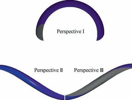
This section gives the value of wheel runout ρ=0.25 mm.The NSGS in this part is researched. According to Eqs. (44) and(45) and the proposed method, the NSGS can be calculated and generated in Matlab, as shown in Fig. 11. By introducing the above surface into Creo and performing Boolean subtraction with blank,the precise three-dimensional surface of workpiece after grinding can be obtained as shown in Fig. 12.

Fig. 11 Envelope surface of NSGS.

Fig. 12 Stimulation processing schematics of NSGS.

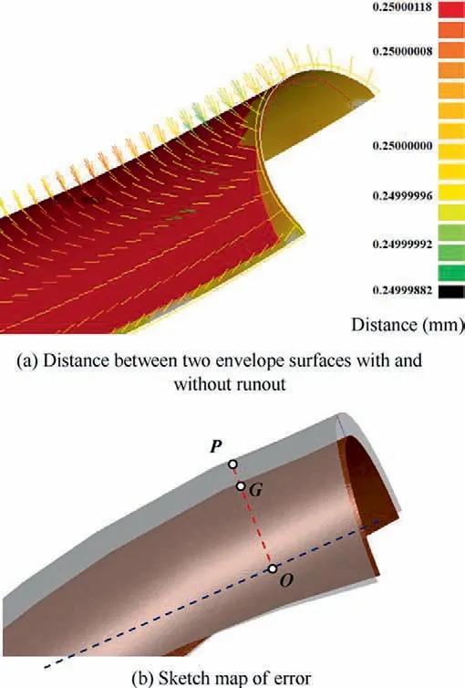
The envelope surface without runout is simulated. The influence of the method is calculated by comparing with and without the runout, the difference between the two is 0.2499-0.25 mm, which is the same as ρ. It is shown as Fig. 13(a).In Fig. 13(b), the definition of ‘‘error” is as follows. The first step is making a line of point P on the envelope surface with runout. This line is vertical to the axis. The foot point is O.This line intersects the envelope surface without runout at point G. The distance between point P and G is the geometric error caused by the wheel runout.
3.4. Analysis and discussion
Firstly, the wheel runout is set artificially in Section 3.1. The runout is calculated using a straight groove in the first experiment. The runout and process parameters are also used in the second one in which spherical inclined groove is adopted.Then, errors are gained and change from -0.0136 mm to 0.0054 mm.This error can satisfy requirement in the high precision grinding process.So,this method can be applied to fiveaxis machining centers because of its high accuracy.
The verification of NSGS is carried out in the software. In Section 3.3, the runout is defined as 0 mm and 0.25 mm. The difference of the envelope surfaces with and without runout is the error.With the wheel runout,the envelope also changes.So, it can be as one of the important factors that cannot be ignored in the five-axis precision machining.

Fig. 13 Schematic of deviation and runout.
Through the comparison of experiment and simulation results, it can be seen the proposed method can meet the precision requirements. At the same time, it can be used to simulate and measure complex surface.
4. Conclusion
Based on the above research,the following conclusions can be obtained:
(1) An algorithm for the grinding envelope surface in the multi-axis grinding is proposed,which is based on envelope theory and considers wheel runout. This algorithm can be applied to any shape of grinding wheel. At the same time, this method can be used to calculate the swept surface of grinding wheel when machining space curved surface.
(2) Two experiments were carried out by using a hemispheric grinding wheel for the DSGS. The wheel runout is artificially set (a 5 mm×1 mm×0.05 mm tape was pasted on the wheel’s mounting handle).The first experimental data was used to calculate the runout, and the accuracy of the algorithm is verified by the second experiment. The error is obtained from -0.0136 mm to 0.0052 mm, which is small enough that the proposed method can meet requirements. At the same time, a NSGS was carried out to verify the accuracy of the algorithm. Different runout deduces different swept surface.In the simulation example, comparing the difference between surfaces with and without runout. It is found that the maximum difference is approximately equal to the runout, which verifies the algorithm’s correctness.
(3) The measurement and extraction of the generatrix for wheels with wear are explained. Therefore, this algorithm is applied to the calculation of the swept surface with runout for the new and worn wheel.
(4) The geometric errors caused by wheel runout are calculated. It is concluded that this kind of error can be understood as systematic errors.
Declaration of Competing Interest
The authors declare that they have no known competing financial interests or personal relationships that could have appeared to influence the work reported in this paper.
Acknowledgements
This research is supported by the National Natural Science Foundation of China (No. 51605147), National Science Fund for Distinguished Young Scholars of Henan Polytechnic University (J2019-2) and Young Backbone Project of Henan Polytechnic University (No. 2018XQG-05).
杂志排行
CHINESE JOURNAL OF AERONAUTICS的其它文章
- Design and experimental study of a new flapping wing rotor micro aerial vehicle
- CFD/CSD-based flutter prediction method for experimental models in a transonic wind tunnel with porous wall
- Prediction of pilot workload in helicopter landing after one engine failure
- Study of riblet drag reduction for an infinite span wing with different sweep angles
- Modulation of driving signals in flow control over an airfoil with synthetic jet
- Strong interactions of incident shock wave with boundary layer along compression corner
