Deformation behaviors of four-layered U-shaped metallic bellows in hydroforming
2020-02-24JingLIUZhiyongLVYngLIULnyunLI
Jing LIU, Zhiyong LV, Yng LIU, Lnyun LI
a Key Laboratory of Materials Processing Engineering, School of Material Science and Engineering, Xi’an Shiyou University,Xi’an 710065, China
b Key Laboratory of Advanced Manufacture Technology for Automobile Parts (Chongqing University of Technology),Ministry of Education, Chongqing 400054, China
c Bime, Bremen Institute of Mechanical Engineering, MAPEX Center for Materials and Processing, University of Bremen,Bremen 28359, Germany
KEYWORDS Deformation behaviors;Four-layered U-shaped bellow;Hydroforming;Numerical simulation;Springback
Abstract Because of the complex constraint effects among layers in multi-layered metallic bellows hydroforming,the stress concentration and defects such as wrinkling and fracture may easily occur.It is a key to reveal the deformation behaviors in order to obtain a sound product. Based on the ABAQUS platform, a 3D-FE model of the four-layered U-shaped metallic bellow hydroforming process is established and validated by experiment. The stress and strain distributions, wall thickness variations and bellow profiles of each layer in the whole process,including bulging,folding and springback stages,are studied.Then deformation behaviors of bellows under different forming conditions are discussed. It is found that the wall thinning degrees of different layer vary after hydroforming,and is the largest for the inner layer and smallest for the outer layer.At folding stage,the wall thinning degree of the crown point increases lineally,and the difference among layers increases as the process going. The displacements of the crown point decrease from the inner layer to the outer layer. After springback, the U-shaped cross section changes to a tongue shape, the change of convolution pitch is much larger than the change of convolution height,and the springback values of the inner layer are smaller than the outer layer. An increase in the internal pressure and die spacing cause the maximum wall thinning degree and springback increase.With changing of process parameters,bellows with deep convolution are easily encountered wall thinning during hydroforming and convolution distortion after springback. This research is helpful for precision forming of multi-layered bellows.
1. Introduction
Due to the advantages of smaller stiffness, greater compensation capabilities and longer lifetime,multi-layered metallic bellows have excellent performance in the complicated working conditions, such as high pressure, high frequency vibration and large axial displacement, and have become important and almost irreplaceable elastic components used in piping,automotive, rocket engine and micro-electromechanical systems,etc.1-4Among various forming methods,such as rolling,electroforming, etc., the hydroforming has become an advanced and preferred technology to form the bellows nowadays because of its advantages of high efficiency and flexibility.5-8A typical bellow hydroforming process is shown in Fig. 1.9
The multi-layered bellow hydroforming is a threedimensional nonlinear physical process with complicated contact behaviors and constraint effects occurred among layers.The deformation behaviors in hydroforming are different for bellows with different material, geometries and the numbers of layers (NoLs, usually from 2 to 6, even more if necessary).It may easily encounter material flows difficulty and stress concentration, which will increase the possibility of defects occurrence, such as wrinkling and cracking. Moreover, the inevitable springback occurs after unloading the pressure and removing the dies. Hence, to avoid the forming defects and realize precision forming in hydroforming, it is necessary to reveal the complicated deformation behaviors of multilayered bellow.
For a four-layered U-shaped bellow used in the rocket engine shown in Fig. 2, the cracking and over-thinning are easily occurred at the crest of bellow in hydroforming. This cause the pass rate less than 40% in manufacturing. To improve forming quality, the deformation behaviors, more specifically, the stress/strain distributions, wall thinning and bellow profiles should be addressed, especially under different loading conditions.In the paper,the deformation behaviors of a typical four-layered U-shaped bellow shown in Fig. 2 are studied.

Fig. 1 A typical bellow hydroforming process.9
Many works were focused on the deformation behaviors of single- or bi-layered bellows/tubes in hydroforming. The researches on the multi-layered bellows with more than two layers were barely reported. To address the deformation behaviors of bellows in hydroforming, some reasonable finite element (FE) models were established. Lee10presented a FE model to simulate the whole single-layered bellow hydroforming process, including bulging, folding and unloading stages.In modeling, an explicit integration method was adopted in bulging and folding stages, while an implicit integration method was used in unloading stage for springback computation.For multi-layered bellows, the main difference compared with the single-layered ones in FE modelling is the constraints between layers. Olabi and Alaswad11established a FE model for bi-layered T-shaped tube hydroforming, and in the model the ‘‘rigid-to-flexible surface-to-surface” contact pair was applied to describe the contact behavior between the outer layer and dies, while ‘‘flexible-to-flexible surface-to-surface”contact pair was chosen for defining the contact behavior between the contacted layers. A similar contact pair was adopted by Islam et al.12in a multi-layered tubular components hydroforming. Also, different friction coefficients were applied to different contact pairs. To improve computational efficiency, a half 3D model is used by Liu et al.13instead of the full model.
Based on the FE models, the influences of geometric and forming parameters on forming results can be addressed so as to reveal the deformation behaviors. The geometric parameters mainly include initial tube thickness, crown and root diameters, convolution shape of the bellow. The forming parameters contains internal pressure, axial force and movement, die stoke, frictional coefficient, etc. Yuan et al.1studied the hydroforming of reinforced s-shaped bellows and pointed out that the internal pressure and the waveform parameters directly affect the hydroforming process. Zhu et al.14investigated the thickness variations under different internal pressures and obtained the forming window in hydroforming an E-seal by employing FE method. Liu et al.15,16addressed the forming behavior of a single-layered bellow in hydroforming considering the effect of bellow geometry, and studied the springback behaviors of a bi-layered bellow.Alaswad et al.17,18obtained the effects of the loading path and geometry parameters on the deformation behaviors.Lee10studied the effects of three main factors, i.e., initial thickness, internal pressure and die spacing on bellow profile and found die spacing is the most influencing one in hydroforming. Bakhshi-Jooybari et al.19studied the effect of internal pressure on forming window and obtained the safe zone.Actually,the geometric parameters have strong influence on the forming parameters in bellow hydroforming. Faraji et al.20-22pointed out that the manufacturing of a metal bellow with high ratio of crown-to-root diameter is very sensitive to forming parameters such as internal pressure,axial movement and die stoke.A similar observation was made by Hashemi et al.23in a CuSn6 bellow hydroforming. They found that cracking may occur with a 3% increase of internal pressure for thin-walled bellows with small diameter.The results demonstrated that with an increase in crown-to-root diameter, the feasible range of forming parameters such as internal pressure decreased significantly.In their works, the deformation behaviors including thickness distribution, crown-point movement and springback behavior were studied through FE analysis.
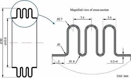
Fig. 2 Dimensions of four-layered U-shaped bellow.
To describe the deformation behaviors in detail,several feature points of the formed bellow are selected in simulation analysis. The displacements of the crown points and the inner points were selected by Lee10to describe the springback of convolution.Except for the two indexes,the maximum convolution width was presented to demonstrate the change of convolution profile in the work of Liu et al.13
Although the research on hydroforming behavior of multilayered bellows with more than two layers was barely reported,the above studies can still provide a profound understanding the multi-layered bellows hydroforming process. In FE modelling,a 1/2 or 1/4 3D FE model can be used and the modelling techniques by Lee10,Olabi and Alaswad11and Liu et al.13can be adopted. In simulation, the stress/strain distributions, wall thinning and bellow profiles under different loading conditions can be investigated combining orthogonal experiment tests and monofactor analysis. The indexes proposed by Lee10and Liu et al.13can be used to describe the deformation behaviors of multi-layered bellows under different loading conditions.
Thus,this study attempts to reveal the deformation behaviors of the 4-layered U-shaped bellow in hydroforming.Firstly,a 3D FE model for the process under ABAQUS platform is explored and validated by comparing the experimental results.Based on the model,the deformation characteristics,including the stress and strain distributions, wall thinning degree and bellow profile variations, are discussed. Furthermore, the effects of process parameters on deformation behaviors for bellows with deep and shallow convolutions are analyzed.
2. FE modelling and validation
2.1. FE model
A 3D-FE model is established to simulate the four-layered Ushaped bellow hydroforming process under ABAQUS platform24, as shown in Fig. 3. The whole simulation contains three stages: bulging, folding and springback (unloading). In the bulging stage, the tube is slightly bulged to ensure it can be fixed between the annular dies;in the folding stage,the tube is formed to the desired shape under the combined action of internal pressure and axial force act on one end of the tubes;while in the springback stage, the pressure is unloaded and the annular dies are removed,the elastic recovery of the material occurs. The explicit algorithm is used in bulging and folding simulation,while the implicit one is employed in unloading computation. To improve computational efficiency, the 1/4 model is used considering the symmetry. The Coulomb’s friction model is chosen to represent the friction behaviors on the interfaces between each contact pair, including the tubedie contact pair and every two adjacent layers. The surfaceto-surface contact algorithm is chosen in computation. The tubes are meshed with four-node doubly curved thin shell elements (S4R), while the four-node bilinear rigid quadrilateral element R3D4 is used in meshing the rigid dies.The Hill’s anisotropic quadratic yield function is used to describe tube material’s yielding behaviors. The strain hardening behavior is described by σ-=K(ε-+ε0)n. The material used in experiment and simulation is AISI304 stainless steel. The length of tube is 94 mm. There are four layers in total and the wall thickness for each layer is 0.2 mm.The geometric dimensions are shown in Fig.2.Tensile tests are performed to obtain the mechanical properties of the tube’s material. The material properties are listed in Table 1.

Fig. 3 FE model for hydroforming of four-layered metallic bellow.

Table 1 Mechanical properties of AISI 304 stainless steel.
It is necessary to produce a successful bellow hydroforming process without wrinkling or fracture occurred in order to analyze the deformation behaviors of bellows in hydroforming.Therefore, the reasonable ranges of forming parameters or a forming window for bellows hydroforming are determined beforehand, such as the works done by Bakhshi-Jooybari et al.19, Faraji et al.20-22, Hashemi et al.23and Gao et al.25.Among the parameters, the internal pressure uniformly applied at the internal surface of tube and the movement of annular dies are important to achieve a qualified bellow10.The internal pressure p is theoretically calculated by Eq. (1)9as following:

where z is the number of layers;t0wall thickness of each layer;σbultimate tension strength; d tube inner diameter.
Actually, the internal pressure used in hydroforming is adjusted based on Eq. (1) and obtained by following steps:
(1) Implementing the bellow hydroforming process applying the internal pressure calculated by Eq. (1);
(2) Calculating or measuring the bellow profile results especially the outer diameter,and comparing with the target value;
(3) Adjusting and obtaining the optimal internal pressure until the outer diameter meets the target value within the error limit.
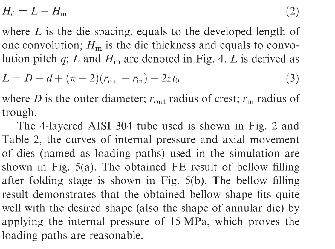
In hydroforming,the two neighboring annular dies contact together finally, the relative displacement of two neighboring annular dies, namely the die stoke Hdis obtained by
2.2. Validation of the FE model
Fig. 4 Parameters denotation in bellow hydroforming.16
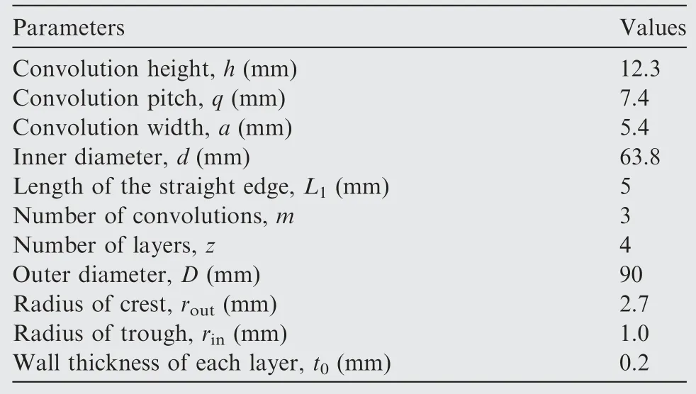
Table 2 Bellow specification in simulation and experiment.
The present FE model is verified using the bellow hydroforming experiment.The forming conditions in the experiment and FE simulation are shown in Table 3, where the internal pressure and die spacing (denoted in Fig. 4) are calculated by Eqs.(1)and(3)and shown in Table 3.The friction coefficients between tube-tube and tube-die are obtained by twist compression test and shown in Table 3.
The experiment is carried out on the hydraulic press CXJ50-320 with nominal force 500 kN and maximum stroke 320 mm. A hydraulic pump with capacity of 63 MPa is used to supply the forming pressure. The four-layered bellow formed by experiment is shown in Fig. 6(a).
The bellow is cut across the center line by electrical discharge machining and the wall thicknesses in cross section are measured by the image measuring instrument Optiv classic 222 designed by Hexagon metrology vision GmbH(Fig. 7). The simulated nodal thicknesses are measured and compared with the experiment at 11 feature points of the four layers (Fig. 6(b)), as shown in Fig. 8. It is found that the simulated thicknesses show a good agreement with the experimental results. Table 4 shows the comparisons between FE results and experiments in terms of convolution pitch and outer diameter. The results show that the predicted convolution pitch and outer diameter deviate from the experiments with relative errors of 5.1% and 1.8%,respectively. Therefore, the FE model is reliable in the prediction of the deformation behavior of the four-layered bellow in hydroforming.
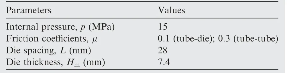
Table 3 Forming parameters.
3. Results and discussion
Knowing the forming quality of bellows is closely related to stress and strain, the distributions of stress and strain of four layers at different forming stages are studied firstly, and then the changes of walling thinning and bellow profile are analyzed. Since loading conditions and deformation behaviors are almost same for each convolution, only one convolution is selected in analysis.
3.1. Stress and strain distributions of different layers
3.1.1. Stress distributions
Figs.9-11 show the equivalent stresses of four layers after bulging, folding and springback, respectively. It is observed that the changing tendency of Mises stress distributions for four layers is almost same; the maximum Mises stress locates at the crest of convolution, and decreases from the crest to the trough. At bulging and folding stages, the maximum Mises stress decreases slightly from the inner layer (the first layer)to the outer layer (the fourth layer). After springback, the Mises stress decreases remarkably, and the residual stresses at the inner layer are larger than the ones at the outer layer.The reason is attributed to the constraint effects between layers. For the outer layer, the springback is free since there is no constraint at the outside. While for the inner layer, there is strong constraint generated from the outer three layers,which limits the springback and leads to the large residual stresses.

Fig. 5 Loading paths used in FE analysis and bellow filling result.

Fig. 6 The four-layered bellow obtained by experiment.
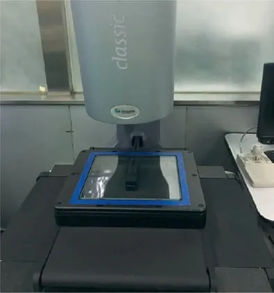
Fig. 7 Image measuring instrument Optiv classic 222.
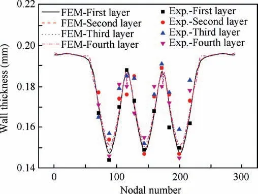
Fig.8 Wall thickness comparison by simulation and experiment.
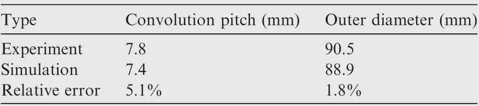
Table 4 Experimental and simulation results.
In order to analyze the change of stress components in hydroforming, the axial and circumferential stress distributions of the inner layer at bulging,50%folding,100%folding and springback stages are studied and shown in Figs. 12 and 13.It is found that,at bulging stage,both the axial and circumferential stresses are tensile, and the maximum axial stress appears at the trough, while the maximum circumferential stress locates at the crest. At folding stage, it is observed that the distributions of the axial and circumferential stresses are complicated in different areas after applying axial force. At the beginning of the folding stage, at the crest of convolution,both the axial and circumferential stresses are tensile, and the circumferential stress is much larger than the axial stress.With an increase in deformation(from 0%folding to 100%folding),the axial tensile stress changes to the compressive stress and is larger than the circumferential tensile stress because of the increase of axial force. While, at the whole folding stage, at the trough of convolution, both the axial and circumferential stresses are compressive stress state, and the axial stress is larger than the circumferential stress. After springback, the axial and circumferential stresses decrease obviously.
3.1.2. Strain distributions
Figs. 14-16 show the equivalent plastic strains of four layers after bulging, folding and springback stages, respectively. It is found that the change tendencies of equivalent plastic strains for four layers are similar to the equivalent stress. However,the values of maximum equivalent plastic strains from the maximum to minimum is the inner layer, the second layer(near to the inner layer), the third layer (near to the outer layer), and the outer layer. After springback, the equivalent plastic strains keep unchanged, which means only elastic recovery occurs without plastic deformation.
Figs. 17-19 show the axial, circumferential and normal plastic strain distributions of the inner layer at bulging, 50%folding and 100% folding stages, respectively. At bulging stage, the axial and circumferential strains are tensile, while the normal strains are compressive. At folding stage, with applying axial force,the axial tensile strain at the crest changes to compressive strain, while the strain state keeps unchanged at the trough of convolution. The axial strain is much smaller than the circumferential and normal ones.
3.2. Deformation behaviors

Fig. 9 Equivalent stress distributions after bulging.
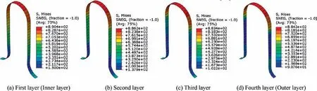
Fig. 10 Equivalent stress distributions after folding.
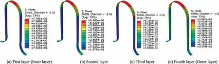
Fig. 11 Equivalent stress distributions after springback.
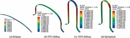
Fig. 12 Axial stress distributions of the first layer (inner layer).
The wall thickness becomes thinning in hydroforming and the springback of bellow profile occurs after unloading (Fig. 20).Therefore,the changes of wall thickness and bellow profile for different layers at different forming stages are discussed in this section.
3.2.1. Wall thinning degree
Fig. 21 shows the wall thinning degree of the bellow after folding stage. It is observed that for the four layers the wall thinning degrees are largest at the crest, and decrease from the crest to the trough; the wall thinning degree decreases from the inner layer to the outer layer, which is similar to the equivalent plastic strain distributions presented in Section 3.1.2. It means that cracking occurs much easily at the inner layer in bellow hydroforming and subsequent usage.
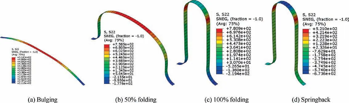
Fig. 13 Circumferential stress distributions of the first layer (inner layer).

Fig. 14 Equivalent plastic strain distributions after bulging.
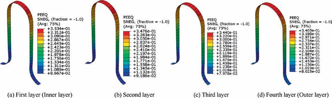
Fig. 15 Equivalent plastic strain distributions after folding.

Fig. 16 Equivalent plastic strain distributions after springback.

Fig. 17 Axial plastic strain distributions of the first layer (inner layer).

Fig. 18 Circumferential plastic strain distributions of the first layer (inner layer).
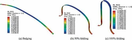
Fig. 19 Normal plastic strain distributions of the first layer (inner layer).
Furthermore, three feature points, the crown point, the middle point of the straight wall and the trough point, are selected to study the changing tendency of wall thickness.Fig. 22 gives the wall thinning degrees at the feature points of four layers during the whole process. It can be found that the wall thinning degrees of the three points increase rapidly at bulging stage; at folding stage, with applying axial force,the increase tendency of wall thinning degrees slows down.At bulging stage, the wall thinning degrees for different layers are almost the same, while at folding stage, the wall thinning degrees of the inner layer are larger than those of the outer layer. From Fig. 22(a), it is observed that the wall thinning degree at the crown point increases linearly at folding stage,and the discrepancy between two layers increases with the process going. Fig. 22(b) shows that the wall thinning degrees at the middle point increase dramatically at the beginning of folding stage and reach to a stable value of 15%after 0.62 s, 59%of total folding time(1.05 s).Fig.22(c)illustrates the wall thinning degrees at the trough point reach a steady value after 0.22 s, 21% of total folding time. It is also can be observed from Fig. 22(c) that the wall thinning degree of fourth layer presents an obvious decline stage at 0.17-0.22 s and a relative small value after 0.22 s compared with the other three.The reason is ascribed to the constraint effect between the annular dies and the fourth layer of bellow. In bulging stage, the annular dies and the fourth layer contact only a tiny region and the wall thinning occurs; In folding stage, as the process going,the contact area of an annular die and the fourth layer increases and the constraint effect at trough point is enhanced.Consequently, the material flow slows and finally induces a decline tendency and a relative small wall thinning degree of the fourth layer compared with the other three.
Since the wall thickness of the hydroformed bellows distributes nonuniformly through the cross section,stress concentration is inevitable occurred in bellow hydroforming which may lead to crack in forming or in subsequent usage under high/low frequency vibration. Therefore, the non-uniformity factor Tdis employed to evaluate the nonuniform deformation. Tdis defined as:
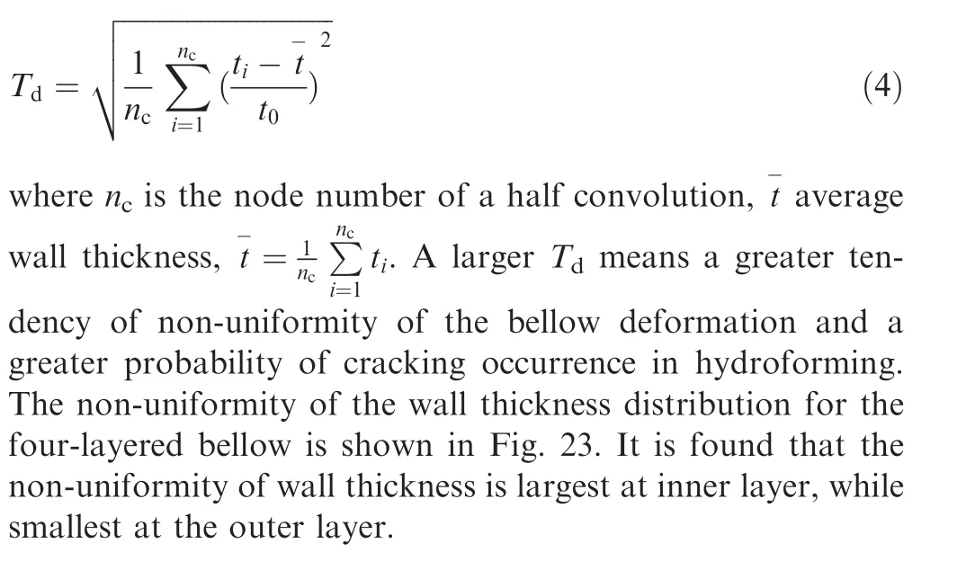
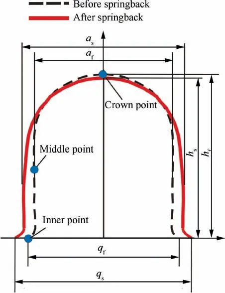
Fig. 20 Sketch of convolution profile before and after springback.

Fig. 21 Wall thinning degree of bellow after folding stage.
3.2.2. Bellow profile
Fig. 24 shows the profiles of the outer layer at different forming stages. It can be seen that the bellow profile is trapezoidshaped at bulging stage, and at folding stage the convolution is formed gradually as the closing of the annular dies.
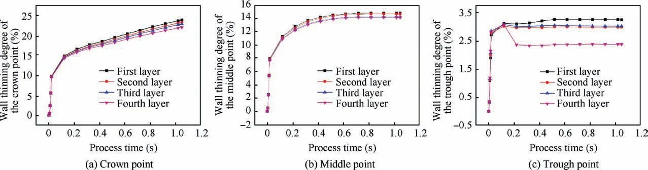
Fig. 22 Wall thinning degree at feature points.
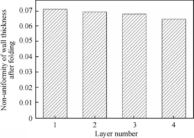
Fig. 23 Nonuniformity of wall thickness for the four layers in hydroforming.
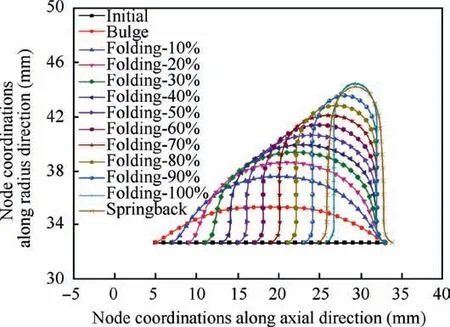
Fig.24 Bellow profiles of outer layer at different forming stages.
The displacements of the crown point at different forming stages are shown in Fig.25.The changing tendencies of the displacements for different layers are similar.At bulging stage(0-0.02 s) the displacement of the crown point increases linearly with the internal pressure increasing. At folding stage (0.02-1.05 s), the movement of the crown point presents a parabolic increase firstly and then a linear increase. At springback stage(1.05-2.05 s), the displacement of the crown point decreases linearly. The changing tendencies at folding and springback stages agree with the results obtained by Lee10in the research of single layered bellow hydroforming, but the changing tendency at the bulging stage are different. In this study, the crown point at bulging stage increases linearly instead of logarithmically indicated by Lee10. The reason is that the simulation times of bulging stage are different for the two studies.In this study,the internal pressure is applied to the inner layer in a relative short time (0.02 s) at bulging stage, thus a linear increase of displacement is observed. Moreover, for the multi-layered bellow, the displacements of the crown points decrease from the inner layer to the outer layer. The displacements of the inner layer and the outer layer are 11.89 mm and 11.76 mm, respectively. This is mainly because the wall thickness becomes thinning after hydroforming and the wall thinning degree of the inner layer is larger than that of the outer layer (Fig. 21).

Fig. 25 Displacement of crown point.
Figs.26 and 27 show the radii of the crest and the trough at different forming stages, respectively. It can be seen that at folding stage the radius of the crest decreases linearly, and the radius of the trough remains unchanged; after unloading,the radii increase slightly.
Owing to the inevitable springback of material,the shape of bellow after unloading always deviates from the designed dimensions, which will have potential influence in subsequent usage. Therefore, the springback of the bellow is analyzed.The convolution shapes before and after springback are addressed in Fig. 28. It is found that after folding stage, the four layers fit closely together and the designed shape and dimensions are obtained;after springback,the U-shaped cross section changes to a tongue shape, the convolution height decreases, while the pitch and thickness increase, and the convolution width is nonuniform along the wave height. To describe the springback characteristics,three indices,including change of convolution height Δh, change of convolution pitch Δq and change of convolution width Δa,are proposed.The Δh,Δq and Δa are defined as:
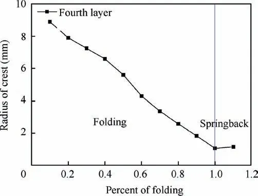
Fig. 26 Radius of crest at different stages of process (1 for 100%).

Fig. 27 Radius of trough at different stages of process (1 for 100%).

Fig. 28 Cross section of four-layered bellow before and after springback.

where hf,qf,afare the convolution height, pitch and width before springback, respectively; hs,qs,asare the convolutionheight, pitch and width after springback, respectively. The six symbols are denoted in Fig. 20.

Table 5 Dimension changes of bellow after springback.
Table 5 shows the changes of convolution height Δh and pitch Δq after springback. It is observed that the Δh is smaller than Δq,which is consistent with the changing tendency of the single layered bellow in Ref. [10]. Moreover, the springback values varies for different layers because of the constraint between layers. The Δh and Δq of the inner layer are 0.01 mm and 0.45 mm, smaller than those of the outer layer.
Fig. 29 shows the change of convolution width Δa after springback. It is found that the Δa decreases with a parabolic tendency from the trough to the crest.The Δa near the trough and the crest are 1.80 mm and 0.45 mm after springback,respectively.
3.3. Deformation behaviors under different forming conditions
The bellows can be divided into two types: deep convolution and shallow convolution according to the difference of expansion ratio k (ratio of outer diameter to inner diameter of bellows). Generally, k∈ (1.3-1.5) is the shallow corrugated bellow, and k∈(1.6-1.9) is the deep corrugated bellow. The expansion ratio affects the performance and forming process of bellows. For bellows with the same inner diameter, the shallow-corrugated bellow exhibits a larger rigidity and smaller displacement compensation,while the deep-corrugated bellow behaves opposite. The forming difficulty of bellows increases with the increase of k. In addition, the literature shows that the internal pressure and die spacing have great influence on the hydroforming process10.Therefore,two kinds of bellows with expansion ratio k=1.4 and k=1.7 are selected in the study, and the wall thickness and profile variations under different process parameters are examined.
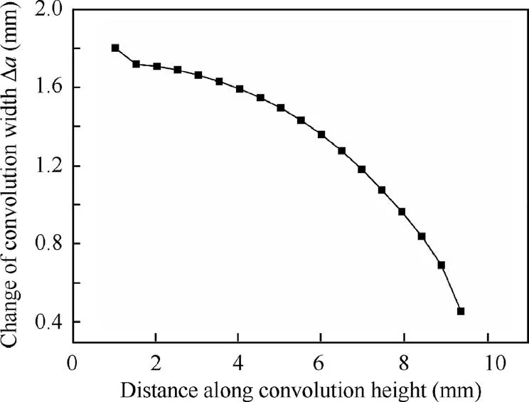
Fig. 29 Change of convolution width after springback.
According to the research in Section 3.2.1,the wall thinning at the crest is most serious for the multi-layered bellows after forming, and the wall thickness of the hydroformed bellows distributes nonuniformly through the cross section, which will affect the service life of bellows. Hence, the maximum wall thinning degree and wall thickness nonuniformity coefficient are selected to study the wall thickness changes of bellows.From Section 3.2.2, it shows that the multi-layered bellows are elongated along the axial direction after springback, and the separation between layer and layer is observed, the big gap between the layers will induce early fracture of bellows under vibration load in pipe systems. Therefore, the change of convolution pitch is selected as an evaluation index to study the profile of bellows after springback.
To evaluate the influence of process parameter sufficiently,five internal pressure and die spacing levels are selected with values of 0%, ±10%, ±20% deviated from the standard values according to the actual forming parameters in Table 3,using monofactor analysis. The simulation experiment arrangement is shown in Table 6.
3.3.1. Wall thickness under process conditions changing
Figs. 30 and 31 show the maximum wall thinning degree with k=1.4 and k=1.7 under different process parameters respectively.It is found that the maximum wall thinning degree increases with an increase in internal pressure and die spacing,and the increased amount of each layer is similar.The reason is that with the increase of internal pressure, the circumferential stress of the bellows increases,which lead to the increase of the bulging height and decrease of the wall thickness. And when the die spacing is enlarged, the material in the deformation area increases, which makes the convolution height increase under the same internal pressure. However, the compensation of the increase of material in the deformation area is less than the loss of wall thickness caused by the increase of radial dimension. Therefore, the wall thinning degree increases.
According to the Chinese standard GB/T 12777-200826which corresponds to EJMA standards,the convolution height deviation of the U-shaped bellows after forming is ±IT18/2.Fig.32 illustrates the convolution height of bellows under different forming conditions.The convolution height of two types of bellows increases linearly with the increase of internal pressure and die spacing.The die spacing has a greater influence on the convolution height than the internal pressure.Whether thedie spacing is too large or too small,it is easy to cause the convolution height out-of-tolerance.

Table 6 Simulation experiment arrangement.
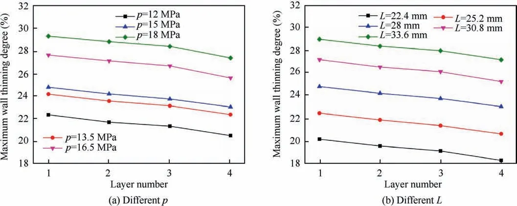
Fig. 30 Numerical results of maximum wall thinning degree for bellows with k=1.4.
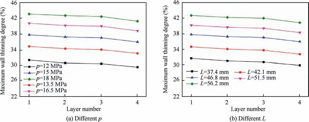
Fig. 31 Numerical results of maximum wall thinning degree for bellows with k=1.7.
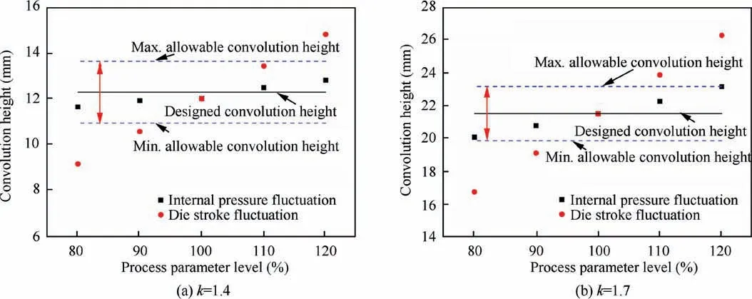
Fig. 32 Numerical results of convolution height for bellows under different process parameters.
For the bellow with k=1.4, the maximum wall thinning degree is 22.3-29.3% when the internal pressure is changing by±20%of the standard value,and that is 20.2-28.9%when the die spacing is changing by ±20%. For the bellow with k=1.7, those are 31.3-43.1% and 31.6-42.7%, respectively.Therefore, it can be deduced that bellows with deep convolution has larger wall thinning degree during hydroforming,and are more sensitive to the change of process parameters.It means that the wall thickness is prone to produce over thinning even cracking easily.
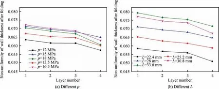
Fig. 33 Non-uniformity of wall thickness for bellows with k=1.4.
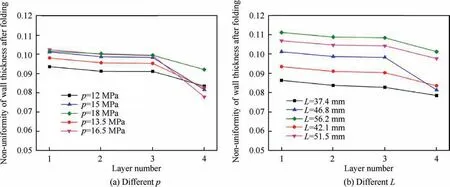
Fig. 34 Non-uniformity of wall thickness for bellows with k=1.7.
Figs. 33 and 34 show the non-uniformity of the wall thickness with k=1.4 and k=1.7 under different process parameters respectively.It is found that with increasing internal pressure and die spacing, the non-uniformity of the wall thickness becomes greater,and the influence of die spacing on wall thickness non-uniformity is greater than that of internal pressure.
3.3.2. Bellow profiles under process conditions change
Figs. 35 and 36 show the change of convolution pitch after springback with k=1.4 and k=1.7 under different process parameters respectively. For two types of bellows, the springback index increases with internal pressure and die spacing,and the change of convolution pitch of the outer layer is slightly larger than that of the inner layer, which means there is a gap between the layers. For bellows of k=1.4, the clearance of the adjacent two layers after springback (obtained by calculating the difference of convolution pitch between two adjacent layers) is within 0.2 mm when the internal pressure changes, and that is within 0.3 mm when the die spacing change s.For bellows of k=1.7,due to excessive bulging,distortion occurs after springback under some process parameters combinations(shown in Fig.37).In the study,the gap between layers less than 0.2 mm is defined as a sound convolution.Apparently,hydroforming a bellow with large expansion ratio will easily encounter forming difficulty, such as distortion,cracking and wrinkling. Therefore, only a small forming window with proper combinations of process parameters can be provided.

Fig. 35 Changes of convolution pitch after springback for bellows with k=1.4.
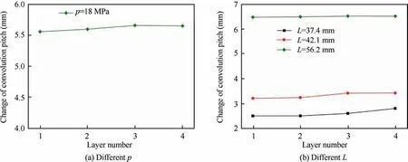
Fig. 36 Changes of convolution pitch after springback for bellows with k=1.7.
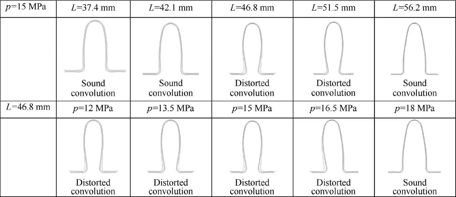
Fig. 37 Cross section profiles after springback for bellows with k=1.7 under different process parameter combinations.
4. Conclusions
(1) The equivalent plastic strain of the inner layer is larger than that of the outer layer. The differences of equivalent stresses of four layers are neglectable small in hydroforming; after springback, the residual stress of the inner layer significantly larger than that of the outer layer.
(2) The wall thinning degrees of different layer varies after hydroforming, and is the largest for the inner layer,and smallest for the outer layer, which means the inner layer is easier to crack in forming and subsequent usage.At folding stage, the wall thinning degree of the crown point increase linearly and the differences among layers become larger as the process going; the wall thinning degree of the middle point increase firstly at the early stage and then keeps stable; the wall thinning degree of the trough point reaches stable at the initial stage of folding and remains same after.
(3) The displacement of the crown point increases linearly at bulging stage, then increases parabolic firstly and linearly at folding stage,and decreases linearly after springback. Moreover, the displacements of the crown points decrease from the inner layer to the outer layer.
(4) At folding stage,the radius of the crest decreases linearly and the radius of the trough remains unchanged; after unloading, the radii of the crest and trough increase slightly.
(5) After springback,the U-shaped cross section changes to a tongue shape,the change of convolution pitch is much larger than the change of convolution height, and the springback values of outer layer are larger than those of the inner layer. The convolution width is nonuniform along the convolution height. The change of convolution width decreases from the trough to the crest zone.
(6) An increasing in the internal pressure and die spacing cause the maximum wall thinning degree and springback increase. With changing of process parameters, bellows with deep convolution are easily encountered larger wall thinning degree during hydroforming and convolution distortion after springback.
Acknowledgments
The authors would like to thank the funds of the National Natural Science Foundation of China (No. 51875456), the Natural Science Basic Research Plan in Shaanxi Province of China(No.2019JM-450),the Young Talent fund of University Association for Science and Technology in Shaanxi, China(No. 20170518), the Key Laboratory of Advanced Manufacture Technology for Automobile Parts (Chongqing University of Technology) , Ministry of Education (No. 2018KLMT03),Materials Science and Engineering provincial-level superior discipline funding project of Xi’an Shiyou University, and the Program for Young Innovative Research Team in Xi’an Shiyou University (No. 2015QNKYCXTD02).
杂志排行

CHINESE JOURNAL OF AERONAUTICS的其它文章
- Design and experimental study of a new flapping wing rotor micro aerial vehicle
- CFD/CSD-based flutter prediction method for experimental models in a transonic wind tunnel with porous wall
- Prediction of pilot workload in helicopter landing after one engine failure
- Study of riblet drag reduction for an infinite span wing with different sweep angles
- Modulation of driving signals in flow control over an airfoil with synthetic jet
- Strong interactions of incident shock wave with boundary layer along compression corner