Robust fault-tolerant attitude control for satellite with multiple uncertainties and actuator faults
2020-02-24LimingFANHiHUANGKixingZHOU
Liming FAN, Hi HUANG,*, Kixing ZHOU
a School of Astronautics, Beihang University, Beijing 102206, China
b Beijing Institute of Electronic System Engineering, Beijing 100854, China
KEYWORDS Actuator faults;Fault-tolerant systems;Input delays;Multiple uncertainties;Satellite attitude control
Abstract In this paper, the satellite attitude control system subject to parametric perturbations,external disturbances,time-varying input delays,actuator faults and saturation is studied.In order to make the controller architecture simple and practical,the closed-loop system is transformed into a disturbance-free nominal system and an equivalent disturbance firstly.The equivalent disturbance represents all above uncertainties and actuator failures of the original system. Then a robust controller is proposed in a simple composition consisting of a nominal controller and a robust compensator. The nominal controller is designed for the transformed nominal system. The robust compensator is developed from a second-order filter to restrict the influence of the equivalent disturbance.Stability analysis indicates that both attitude tracking errors and compensator states can converge into the given neighborhood of the origin in finite time. To verify the effectiveness of the proposed control law, numerical simulations are carried out in different cases. Presented results demonstrate that the high-precision attitude tracking control can be achieved by the proposed fault-tolerant control law. Furthermore, multiple system performances including the control accuracy and energy consumption index are fully discussed under a series of compensator parameters.
1. Introduction
Attitude Determination and Control System (ADCS) is an essential subsystem in most spacecrafts. It has great impact on many space missions like earth-pointing photography,spacecraft formation flying and space rendezvous, etc. Therefore, lots of researches1-5have been done for better attitude control performance. However, in practical engineering, the satellite attitude tracking system is not only nonlinear and coupled,but also subject to parametric perturbations,external disturbances, time-varying input delays, actuator faults and saturation. These disturbance items make the high-precision attitude control still challenging. Meanwhile, the developed controller architecture could not be too complicated to realize.In this background,this paper aims to propose a robust faulttolerant controller in a simple configuration, so that the highprecision attitude tracking control can be achieved under multiple uncertainties and actuator faults.
Generally, the existing Fault-Tolerant Control (FTC)methods can be classified into two types6: Active FTC7-9and passive FTC.10,11The active FTC method attempts to detect and diagnose the actuator failure firstly. Then the controller architecture can be adjusted actively for better system performance based on the detected failure. In some typical systems where actuator failures are detectable, this method is well targeted and effective.However,the Fault Detection and Diagnosis (FDD) mechanism requires on-line and real-time system information.It is difficult to implement this method if actuator failures are undetectable or the system is time-delayed. Differently, the passive FTC method aims to develop a controller robust to actuator failures without changing the controller architecture. There is no need to diagnose the exact time and form of actuator failures. It is desirable in practical engineering. Therefore, in this paper, authors choose to derive the fault-tolerant attitude control law from the passive FTC method.In Refs.12,13,the observer-based H∞control scheme was studied for the spacecraft ADCS with actuator faults. To restrict the influence of actuator and sensor failures, an auxiliary observer was developed to estimate system states and faults.Then a H∞output feedback FTC scheme was proposed for the closed-loop system.12In Refs. 14-16, the Extended State Observer (ESO) approaches were introduced to handle system uncertainties and actuator failures. In recent works,Li et al.15combined the finite-time methodology and ESO to estimate the angular velocity and synthetic failures simultaneously.Then a continuous finite-time robust controller was proposed based on the terminal sliding mode control and supertwisting method for a spacecraft attitude stabilization system.It is commendable that multiple advanced control techniques have been combined to achieve their complementary performances. Due to the great robustness, Sliding Mode Control(SMC) method has been researched widely15,17-20in the fault-tolerant attitude control system of spacecrafts. In Ref.17, the failure mode effect criticality was analyzed to classify different failure types of reaction wheel. Then an adaptive SMC algorithm was developed to estimate the actuator faults and correct their negative effects.In Ref.19,two sliding mode observers were proposed for a satellite attitude stabilization system without rate sensor. They were developed to estimate the attitude angular velocity and reconstruct actuator faults separately. Based on the reconstructed value, a velocity-free sliding mode controller was achieved to stabilize the closedloop system asymptotically.
In practical engineering,input time-varying delays21-24and actuator saturation22,25-28should also be addressed in the controller design. Different with above actuator failures, time delays and actuator saturation are inherent hardware properties of the control system. Generally, the stability of timedelay systems can be guaranteed by the Lyapunov-Krasovskii approach. In Ref. 21, the difference of control inputs caused by time delays was regarded as a disturbance which could be restricted by a proposed robust compensator.In Ref.22,a sliding mode delay-dependent controller was proposed while model uncertainties and disturbances were handled by Chebyshev Neural Networks (CNN). Furthermore,the actuator saturation problem was solved based on command filter and backstepping design techniques. In Ref. 25, a self-modified gain matrix was introduced in the proposed controller to drive actuators within the desired boundaries.In Ref.28,a novel dynamic linearization model was established firstly for a combined spacecraft where external disturbances and linearization errors could be reconstructed by a discrete ESO.Then an adaptive control law and an anti-windup compensator were proposed for the closed-loop system under actuator saturation. Moreover, some novel FTC algorithms were studied based on self-tuning fuzzy Proportional-Integral-Deriva tive (PID) approaches29and Takagi-Sugeno (T-S) fuzzy techniques.30However,it can be noticed that only a few FTC algorithms22,29can restrict the negative influence of input delays and actuator saturation at the same time. In the light of this,this paper aims to propose a robust fault-tolerant attitude control law,which is not only robust to parametric perturbations,external disturbances,input delays,actuator faults and saturation, but also easy to realize in practical engineering.
Compared with other related researches,the main contributions of this paper can be summarized as follows:
(1) The original time-delayed system subject to multiple uncertainties and actuator faults is transformed into a disturbance-free nominal system and an equivalent disturbance.
(2) A robust fault-tolerant attitude controller is proposed in a simple composition consisting of a nominal controller and a robust compensator.
(3) The robust compensator is constructed from a secondorder filter to restrict the negative influence of the equivalent disturbance.
(4) Stability analysis indicates that both attitude tracking errors and constructed compensator states can converge into the given neighborhood of the origin in finite time.
(5) The proposed controller requires no information of actuator faults and keeps parameters time-invariant.These properties are desirable in practical engineering.
The remainder of this paper is organized as follows:In Section 2, the mathematical model of the satellite attitude FTC system is formulated.In Section 3,the robust controller design methodology and the guideline to determine controller gains are presented. In Section 4, stability analysis is conducted in the closed-loop system. In Section 5, numerical simulations are carried out and discussed in different cases. In Section 6,conclusions are drawn.
2. Mathematical model formulation
2.1. Satellite attitude tracking model
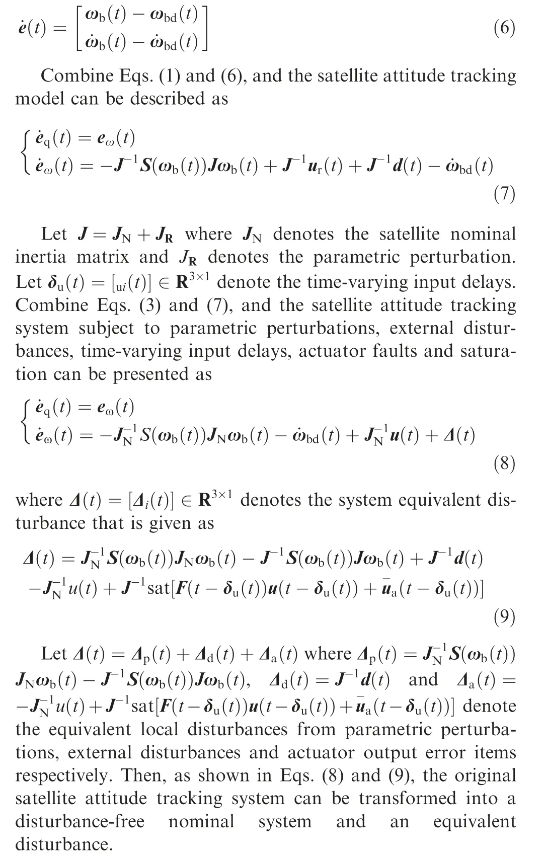
In this paper, the inertial coordinate system and the satellite body-fixed coordinate system are presented as Fiand Fbrespectively. Then the satellite attitude dynamic model can be presented in Fbas follows6:

where J ∈R3×3is a constant symmetric matrix representing the satellite inertia moment, ωb(t)=[ωbi(t)]∈R3×1denotes the satellite angular velocity in Fb, ur(t)=[uri(t)]∈R3×1denotes the real actuator output, and d(t)=[di(t)]∈R3×1denotes the external disturbance. S(ωb(t)) represents the skew-symmetric matrix of ωb(t) and is given as

Before the controller design, the following boundedness assumptions are made:
Assumption 1. The equivalent local disturbances Δp(t)and Δd(t)are bounded.
Assumption 2. The additive actuator fault Δa(t) and the input delays δu(t)are bounded.Let δm=‖δu(t)‖∞denote the boundary of the input delay.
2.2. Control objective
Based on the transformed system (8), the control objective of this paper can be described as: Developing a robust faulttolerant attitude controller u(t) such that:
(1) The high-precision attitude tracking control can be achieved by the proposed controller without information of actuator fault or input delay.
(2) The proposed controller should be time-invariant with a simple architecture.
3. Robust controller design methodology
In this section, the robust fault-tolerant controller design methodology is presented. The control strategy is shown in Fig. 1. The proposed control law contains two modules: (A)a nominal controller uN(t)=[uNi(t)]∈R3×1;(B)a robust compensator uR(t)=[uRi(t)]∈R3×1.
In principle, the nominal controller is designed for the transformed nominal system;the robust compensator is developed from a second-order filter to restrict the influence of the equivalent disturbance. Then the robust controller u(t) can be presented as
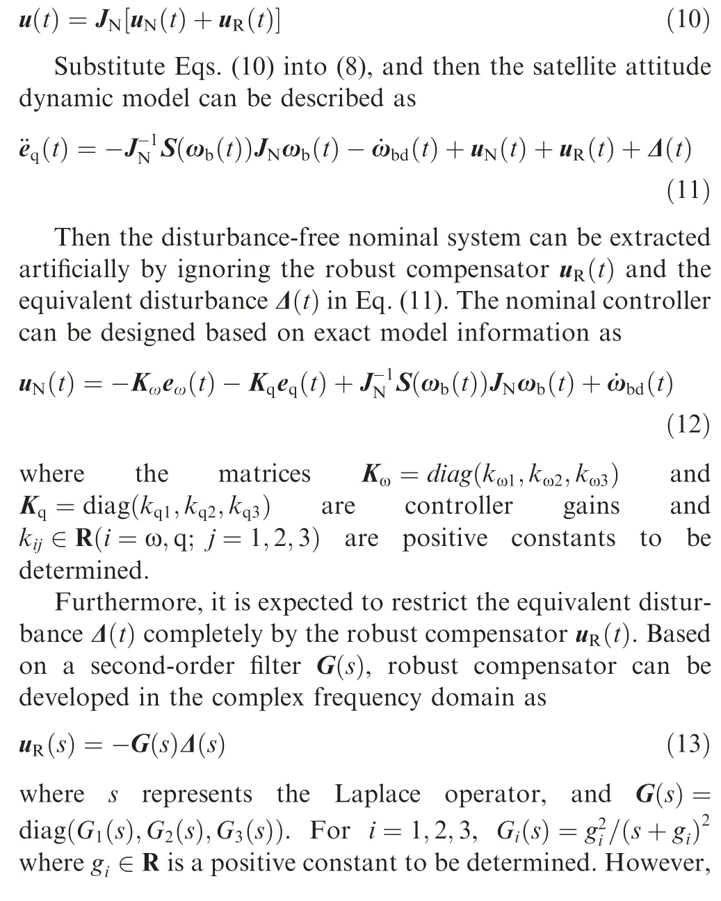

where r1(t)=[r1i(t)]∈R3×1and r2(t)=[r2i(t)]∈R3×1denote the compensator states, andG=diag(g1,g2,g3)is a diagonal constant matrix consisting of compensator parameters. It can be noticed that the parameter G has great influence on both compensator outputs and the stability of the compensating state space. Then the proposed robust controller u(t) can be given by Eqs. (10), (12) and (15).
Furthermore, the guideline to determine the nominal controller gains Ki(i=ω,q) and the compensator parameter G is presented as follows:
Step 1. Extract the disturbance-free nominal system from Eq. (11), and then select the nominal controller gains Ki(i=ω,q) appropriately according to the desired performance.
Step 2. Select the robust compensator parameter G sufficiently large. Generally, the control accuracy of the closedloop system can be improved effectively.
Step 3. In order to save energy, the robust compensator parameter G can be reduced to an appropriate value under the premise of meeting the control accuracy requirement.

Fig. 1 Proposed control strategy of closed-loop system.
Step 4. If the desired control accuracy cannot be achieved by only tuning the compensator parameter G, it is recommended to return to Step 1, select larger nominal controller gains Ki(i=ω,q), and then proceed to Step 2 and Step 3.
Remark 1. It is observed that the proposed controller in Eq.(10) requires no information of actuator fault. Moreover, the nominal controller gains Ki(i=ω,q) and the compensator parameter G are positive constant matrices. Therefore, the proposed controller architecture is simple and time-invariant.These properties are desirable in practical engineering.
Remark 2. Based on the nominal control law in Eq. (12),the nominal system can be simplified as ¨eq(t)+Kω˙eq(t)+Kqeq(t)=0. It evolves into a typical Proportional-Derivative(PD) control system. Obviously, if nominal controller gains Kωand Kqare selected with suitable values, one can assign the poles of the nominal system to any expected value.
Remark 3. It can be noticed that the robust filter G(s) in Eq.(13) indicates a low-pass filter. If parameters gi(i=1,2,3)are chosen large enough, the frequency band-width of the low-pass filter would be sufficiently wide and the robust compensating output uR(s) would approximate to -Δ(s).Furthermore, in the second-order control system Eq.(11),the robust filter Gi(s) can also be promoted as
Gi(s)=gifi/[(s+gi)(s+fi)],(i=1,2,3) where gi∈R and fi∈R are positive constants to be determined. Then the performance of the robust compensator can be adjusted with three more parameters fi(i=1,2,3).
4. Stability analysis of closed-loop system
In this section, the stability analysis of the closed-loop system is conducted. It can be found that the convergence of attitude tracking errors ei(t)(i=q,ω) and compensator states ri(t)(i=1,2) is the key to system stability. Since the robust compensator uR(t) contains the robust controller u(t) as a feedback in Eq.(15),it is difficult to give the state-space equation of the closed-loop system directly.Therefore,it is expected to find an equivalent expression of the robust compensator.


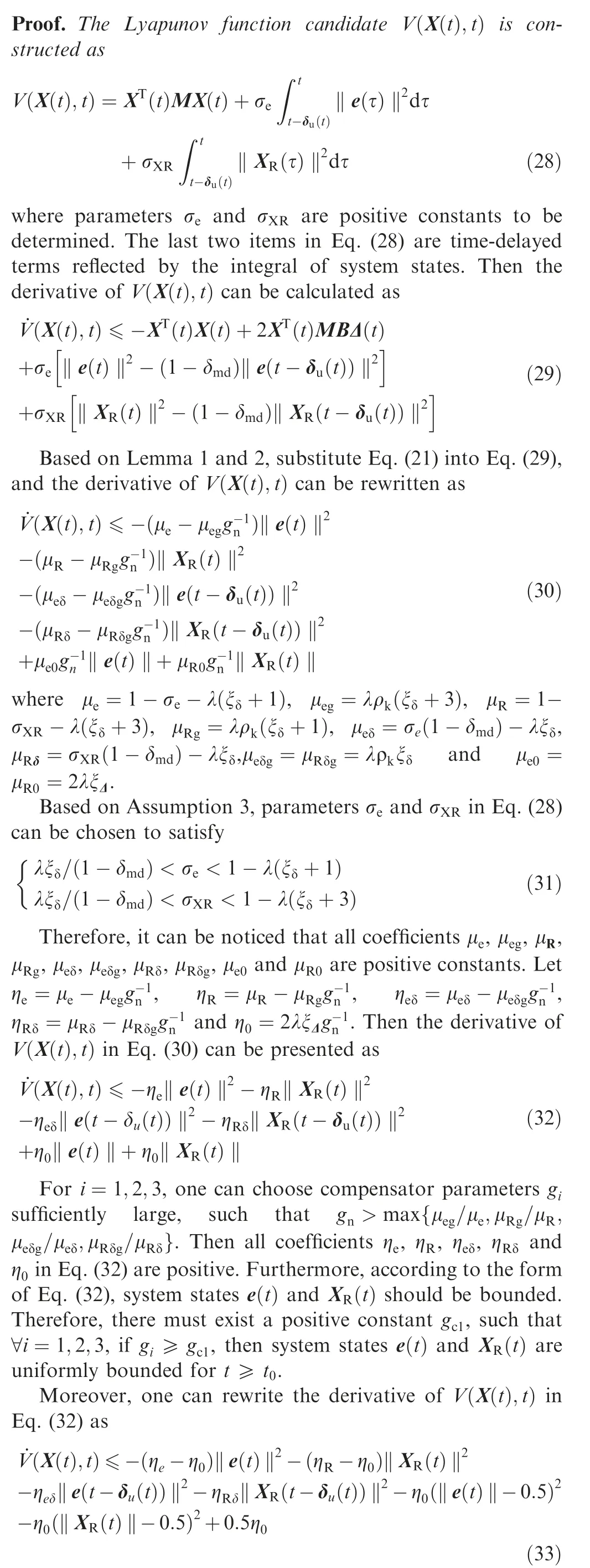
It is noticed that the convergence domain of the closed-loop system is guaranteed to 0.5η0. Since η0=2λξΔg-1n, one can reduce η0as small as desired by choosing gnsufficiently large.Therefore, there must exist a positive constant gc2, such that∀i=1,2,3, if gi≥gc2, then coefficients (ηe-η0) and(ηR-η0)in Eq.(33)are positive.For a given positive constant ε, there exists another positive constant gc3, such that∀i=1,2,3, if gi≥gc3, then η0≪2ε.
Let gc=max{gc1,gc2,gc3}. It can be concluded that: for a given positive constant ε, there exists a positive constant tc,such that ∀i=1,2,3, if gi≥gc, then system states e(t) and XR(t) satisfy that ‖e(t)‖≤ε and ‖XR(t)‖≤ε for t ≥tc.
From Lemma 1, Lemma 2 and Theorem 1, the stability of the closed-loop system can be guaranteed.Based on the definition of XRi(t)(i=1,2,3),the original compensator states r1i(t)and r2i(t)can be presented as a linear combination of Ei(t)andXRi(t) which have been proven to converge in finite time.Therefore, the original compensator states ri(t)(i=1,2) are also converged. Meanwhile, it should be mentioned that if the expected attitude angular acceleration always exceeds the actual acceleration that the failed actuator can produce, no controller can do anything.
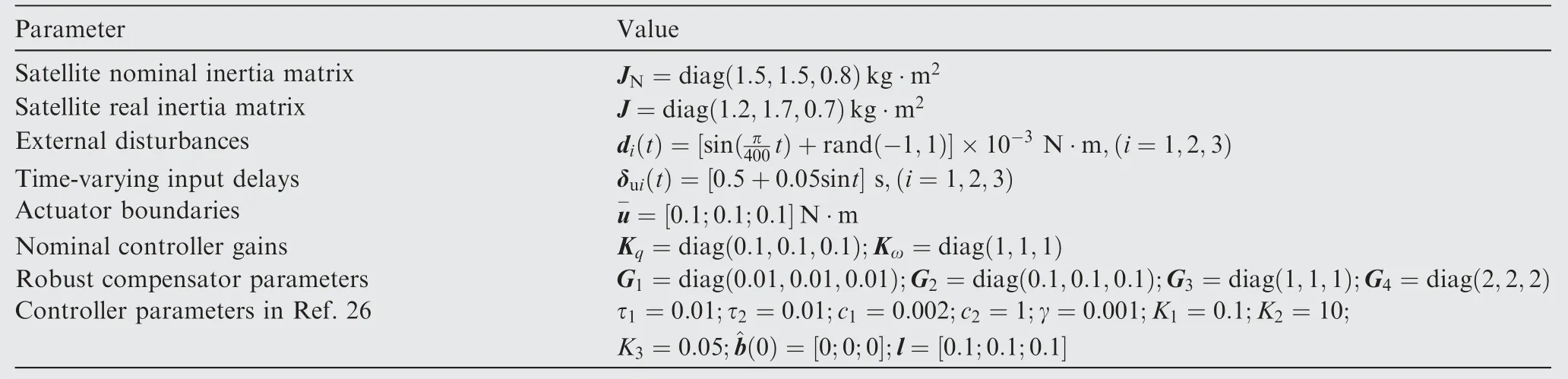
Table 1 Model parameters and controller gains.

Fig. 2 Multiplicative failure scenarios of actuators.

Fig. 3 Error Euler angle eΘ(t) in Case 1.
Remark 4. Actually,the state-space realization in Eq.(16)can also be derived from the robust compensator Eq.(13)directly.It testifies the equivalence and correctness of Eqs. (15) and(16).However,only the state-space realization Eq.(15)can be used in practical engineering because the equivalent disturbances Δi(t)(i=1,2,3) are unmeasurable in Eq. (16).

Fig. 4 Error angular velocity eω(t) in Case 1.

Fig. 5 Combined system state XR(t) in Case 1.
Remark 5. From the stability analysis, if the compensator parameters gi(i=1,2,3)are selected larger,the attitude tracking error e(t) and the compensator state XR(t) of the closedloop system will be smaller. It indicates better robustness to the equivalent disturbance. This is consistent with the conclusion of the frequency domain analysis in Remark 3.
5. Numerical simulations and full discussion
In this section, numerical simulations are carried out to verify the effectiveness of the proposed control law in a microsatellite attitude tracking system. It contains two different cases: (A)ramp signal tracking; (B) sinusoidal signal tracking.In addition, the adaptive fault-tolerant controller in Ref. 26 is referred to as ‘‘comparison”. The control scheme can be given as26
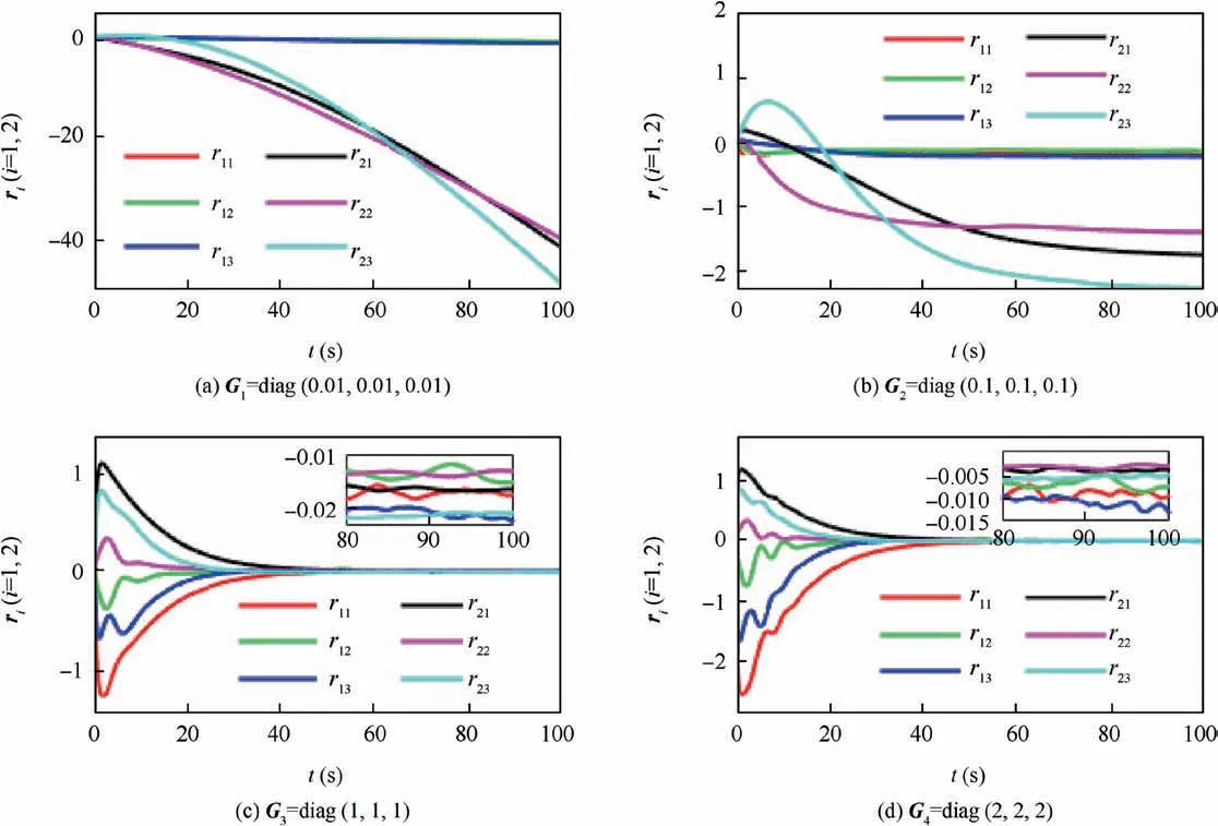
Fig. 6 Original compensator state ri(t)(i=1,2) in Case 1.
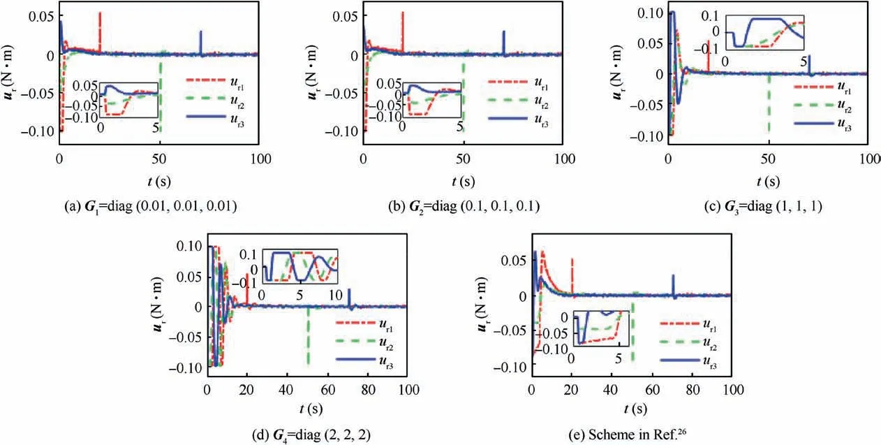
Fig. 7 Real actuator output ur(t) in Case 1.

Fig. 8 Bar graph of energy index in Case 1.

Fig. 9 Time response of total energy consumption in Case 1.

Case 1. The satellite is required to rotate at a constant angular velocity as ωbd(t)=[1;-1;0.5] (°)/s from Θd(0)=[0;0;0] (°).The real initial conditions are set as Θ(0)=[50;-30;75] (°)and ωb(0)=[3;2;-7] (°)/s. Let eΘ(t)=Θ(t)-Θd(t)=[eΘi(t)]∈R3×1denote the error Euler angle. Then the system performance can be discussed fully under four sets of compensator parameters Gi(i=1,2,3,4) and the control scheme in Ref. 26. The error Euler angle and error angular velocity are shown in Fig. 3 and Fig. 4 respectively. It can be observed that larger compensator parameters lead to smaller attitude tracking errors. Specifically, in scenario G3=diag(1,1,1), the steady-state error Euler angle eΘ(t)and error angular velocity eω(t) can be dominated within[0.15;0.07;0.15] (°) and [0.04;0.04;0.05] (°)/s in roll, pitch and yaw axes.They are much smaller than G1and G2scenarios but larger than G4scenario. It is also noticed that the system convergence speeds are close under different compensator parameters. Meanwhile, the control scheme in Ref. 26 can achieve similar performance with G3scenario but not as good as G4scenario. In Figs. 5 and 6, the combined system state XR(t) and original compensator states ri(t)(i=1,2) are presented respectively. In Scenario G1, neither of the above states can converge.It indicates an unstable state of the closedloop system. Furthermore, with the increase of compensator parameters, the above states converge into a smaller neighborhood of the origin and the closed-loop system tends stable.This performance is consistent with the result of stability analysis.
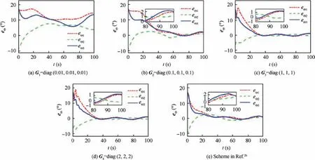
Fig. 10 Error Euler angle eΘ(t) in Case 2.
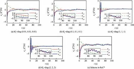
Fig. 11 Error angular velocity eω(t) in Case 2.

Fig. 12 Combined system state XR(t) in Case 2.
Furthermore, the real actuator output ur(t) is presented in Fig. 7. Multiple uncertainties including input delays, actuator saturation and additive failures can be observed. It is also noticed that larger compensator parameters lead to more severe saturation problem.This is logical because larger compensator parameters will drive greater compensation torques. In addition, compared with Gi(i=1,2,3,4) scenarios, the control scheme in Ref. 26 prevents saturation by introducing an arc tangent function in f(u). Then the real actuator output keeps decreasing under the effect of matrix F(t)at initial time.Correspondingly, the actuator power consumption is analyzed. The system energy index and its time response are introduced as31
where E ∈R denotes the energy index and T ∈R denotes the simulation time. As shown in Fig. 8 and Fig. 9, it can be observed that the system with larger compensator parameters consumes more energy. However, the electrical energy is critical but scant for satellites. Therefore, if the desired attitude control accuracy is achieved,there is no need to select compensator parameters too large. Meanwhile, the energy consumption in stable phase is close in all scenarios. This phenomenon is different in Case 2.

Fig. 13 Original compensator state ri(t)(i=1,2) in Case 2.

Fig. 14 Real actuator output ur(t) in Case 2.
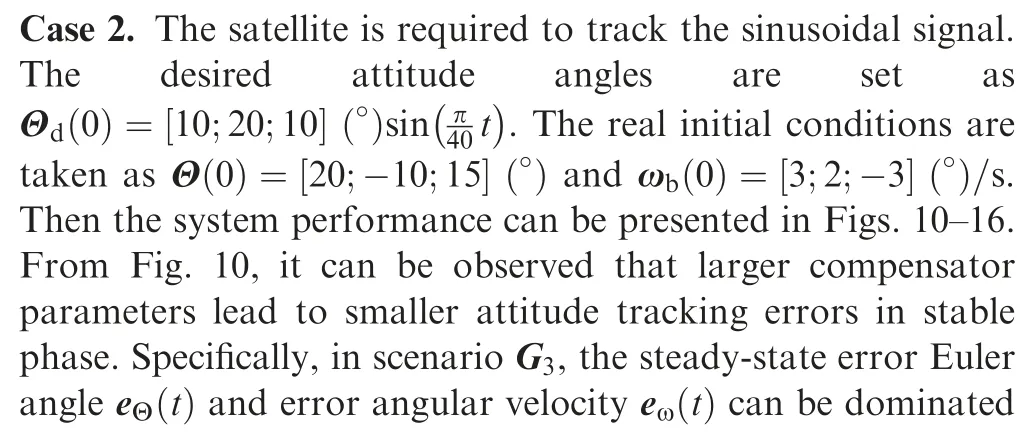
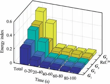
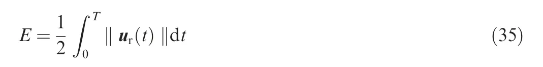
Fig. 15 Bar graph of energy index in Case 2.
Fig. 16 Time response of total energy consumption in Case 2.
Furthermore, the real actuator output ur(t) is presented in Fig. 14. Similar with Case 1, multiple uncertainties like input delays and additive actuator failures can be observed.It is also noticed that the saturation constraint can be satisfied by the proposed controller and the scheme in Ref. 26. Meanwhile,compared with Case 1, the controller output is larger in the stable phase because the steady-state error is larger in sinusoidal signal tracking case. This behavior is also reflected in the steady-state energy consumption and its time response as shown in Fig.15 and Fig.16.Same as Case 1,the system with larger compensator parameters consumes more energy. At the beginning of attitude maneuvering, the system energy consumption is fast and the slope of its time response is close to a constant value. This is because the large system errors at the initial moment excite the actuator to saturation where‖ur(t)‖is constant and maximum.In comparison,the control scheme in Ref.26 costs more energy in the stable phase and its total energy consumption is more than G3scenario. This phenomenon is different with Case 1.
In addition, to make the numerical simulation clearer and more quantifiable, the simulation data of Case 1 and Case 2 are presented in Table 2. Multiple system performances can be observed directly from this table.For example, as the compensator parameters increase, the attitude tracking errors and compensator states converge to a smaller value in both cases.
From a practical engineering perspective, if the desired angular acceleration in Case 2 exceeds the actual acceleration that the failed actuator can produce,no controller can do anything in this period. More powerful actuators are usually selected to avoid this dilemma. Meanwhile,since the sampling time is fixed and cannot be infinitely small, it is impossible to reduce the system error infinitely only by adjusting the controller gains. Therefore, it is not necessary to select the compensator parameters excessively large. On the premise that the desired attitude tracking performance is achieved,it is recommended to select the compensator parameters small to savesystem energy.Compared with the scheme in Ref.26,the proposed controller architecture is simple and easy to realize in practical engineering. In Case 1, similar with G3scenario, the scheme in Ref. 26 can also achieve high-accuracy attitude tracking control in small energy consumption. In Case 2, the proposed control law leads to higher control accuracy and smaller energy consumption in the stable phase.

Table 2 Main simulation data and comparison.
In summary, simulation results demonstrate that the performance of closed-loop system is consistent with the result of stability analysis. Furthermore, the proposed faulttolerant control law is verified to be effective to achieve the high-precision attitude tracking control in a microsatellite subject to parametric perturbations, external disturbances, timevarying input delays, actuator faults and saturation.
6. Conclusions
This paper investigates the attitude tracking system of a satellite subject to parametric perturbations,external disturbances,time-varying input delays,multiple actuator faults and saturation.To realize the high-precision attitude control,the original closed-loop system is transformed into a disturbance-free nominal system and an equivalent disturbance firstly. The equivalent disturbance is a centralized expression of system uncertainties and actuator failures. Then a fault-tolerant attitude controller consisting of a nominal controller and a robust compensator is proposed correspondingly. The nominal controller is designed to stabilize the nominal system. The robust compensator is developed from a second-order filter to restrict the negative influence of the equivalent disturbance. Furthermore, it is proven theoretically that both attitude tracking errors and constructed compensator states can converge into a given neighborhood of the origin in finite time. Finally,numerical simulations are carried out to verify the effectiveness of the proposed control law. The performance of the closedloop system is consistent with the result of stability analysis.Simulation results demonstrate that the desired high-precision attitude tracking control can be achieved by the proposed control law under multiple uncertainties and actuator faults.
Future works will focus on the improvement of the proposed robust compensator. By combining some advanced observer techniques, the authors hope to propose a composite control law to improve the attitude control accuracy in a complex flexible satellite.
Acknowledgements
This study was supported by the APSCO (Asia-Pacific Space Cooperation Organization) Student Small Satellite (SSS) Project (Microsatellite SSS-1, No. APSCO/ET&DM/ SSS/IMP_C_001).
Appendix A.Derivation of robust compensator uR(t)in Eq.(15).
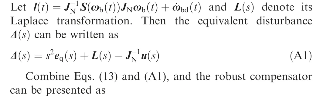
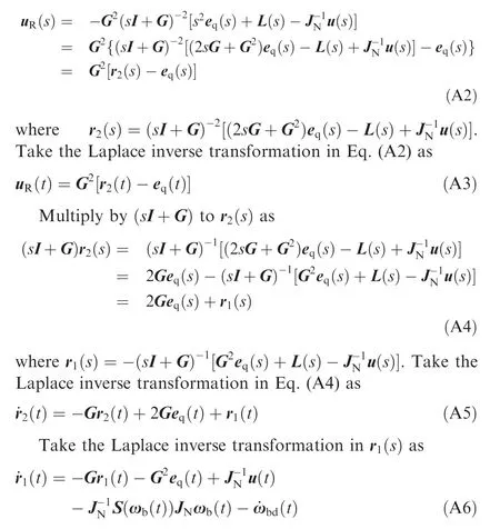
It can be found that the state-space realization Eq. (15) of the robust compensator uR(t) is the combination of Eqs.(A3),(A5)and(A6).In summary,the derivation process from Eqs. (13) and (14) to Eq. (15) is completed.
杂志排行
CHINESE JOURNAL OF AERONAUTICS的其它文章
- Design and experimental study of a new flapping wing rotor micro aerial vehicle
- CFD/CSD-based flutter prediction method for experimental models in a transonic wind tunnel with porous wall
- Prediction of pilot workload in helicopter landing after one engine failure
- Study of riblet drag reduction for an infinite span wing with different sweep angles
- Modulation of driving signals in flow control over an airfoil with synthetic jet
- Strong interactions of incident shock wave with boundary layer along compression corner