Modeling and analysis of solar Doppler difference bias with arbitrary rotation axis
2020-02-24JinLIUYngyngLIXiolinNINGXioCHENZhiweiKANG
Jin LIU, Yngyng LI, Xiolin NING, Xio CHEN, Zhiwei KANG
a College of Information Science and Engineering, Wuhan University of Science and Technology, Wuhan 430081, China
b College of Instrument Science and Optoelectronic Engineering, Beihang University, Beijing 100191, China
c Shanghai Institution of Satellite Engineering, Shanghai 200240, China
d College of Information Science and Engineering, Hunan University, Changsha 410082, China
KEYWORDS Bias;Doppler navigation;Measurement;Modeling;Rotation
Abstract The solar rotation causes the solar Doppler difference bias,which leads to the decline of the velocity measurement accuracy.Modeling and compensation are an effective solution.The limited model with specific geometric direction, where the solar rotation axis is perpendicular to the plane through the Sun, the Earth and Mars, was established. However, in fact, the geometric relationship among the Sun,Mars and the spacecraft is not fully in line with the hypothesis of the model due to the spacecraft orbital angle and the solar rotation axis drift. Thus, this model is not consistent with the fact. In order to solve this problem, a universal solar Doppler difference bias model,which provides the expression with arbitrary rotation axis, is established in this paper. In this method, for any point at the solar surface, four variables including the direction of the solar rotation linear velocity at this point, the distance from this point to the rotation axis, the vector from this point to Mars, and the vector from this point to the spacecraft are calculated. Based on these four variables, the solar Doppler difference bias corresponding to this point is obtained. The theoretical analysis and simulation results demonstrate that the solar Doppler difference bias model with the actual rotation axis is different from that with one of the specific rotation axes.Therefore,it is indispensable to build the proposed model for compensation.Besides,the direction of the solar rotation axis, the spacecraft-Mars-Sun angle and the spacecraft-to-Mars distance are important impact factors for the proposed model.
1. Introduction
The status of the sun in the solar system is self-evident.The use of solar light for autonomous navigation1,2has long been studied.In 1960,Franklin RG of the Franklin Institute of the United States proposed the idea of determining the velocity of a detector by measuring the Doppler shift of the celestial spectrum.3Since the 1990s, the solar Doppler radial velocity has been exploited to navigate for spacecraft.In 1999,Guo et al.4,5has proposed the celestial navigation method using the solar Doppler radial velocity and the direction of the solar vector.Long et al.6has proposed an autonomous navigation method using celestial objects and Doppler measurements in 2000.Since then,to improve the navigation accuracy,the solar Doppler radial velocity measurement information was combined with the sun line-of-sight vector7,8or the X-ray pulsar timeof-arrival.9However, the solar spectrum is extremely unstable and unpredictable.10This leads to high error of velocity measurement.
To address this problem, in 2015, the Sun Doppler difference navigation method was developed.The solar Doppler difference navigation system11is an emerging and promising navigation method.In this navigation method,the direct solar spectrum is compared with the reflected spectrum from Mars.And the Doppler differential velocity as a navigation measurement is obtained.Obviously,the solar Doppler difference measurement effectively eliminates the common error that arises from the solar spectral instability.12-15Besides, the approach phase16of deep space exploration is of vital importance.In this phase,the celestial navigation17is irreplaceable due to its realtime property. Fortunately, the solar Doppler difference navigation is only suitable for the approach phase as it needs to observe the extremely weak sunlight reflected by Mars. Therefore, the solar Doppler difference navigation,18,19as an effective and important navigation method, continues to attract attentions.Hereafter,the research on the solar Doppler difference is in full swing.For navigation scheme,the solar Doppler difference/X-ray pulsar integrated navigation11was developed in 2015. For measurement model, the solar Doppler double measurement model20was proposed to take full advantage of the solar spectrum information in 2017. For estimation algorithm, in 2018, Pantalone and Kudenov21used the Doppler shift of Fraunhofer lines for autonomous navigation.Lanza et al.22has investigated the accuracy of the solar radial velocity. Besides, the solar radial Doppler difference measurement model23for formation flight was also developed.
The analysis of error sources24is critical for the autonomic navigation system as the error characteristics of the navigation system25,26are the prerequisite for the navigation system design.If the error is very high,the accuracy of the navigation system declines greatly, which makes the navigation system unavailable. The error analysis research for the solar Doppler difference navigation system is still in the initial stage. The errors of the solar Doppler difference navigation system can be categorized into three categories such as the optical errors27caused by solar spectral fluctuations and the Mars reflections,the spectrometer noise,and the geometric bias28from the solar feature - a giant rotating sphere. Generally, signal processing algorithms such as Kalman filter reduce the random noise,whilst bias modeling and compensation is an effective solution for system bias. In 2019, Liu et al.29analyzed the geometric bias of the solar Doppler difference navigation system. Three geometric bias sources related to the Sun are identified: (A)the area overlap rate of the direct and the reflected sources;(B) the spread effect of the time difference of arrival; (C) the solar rotation Doppler difference bias.The conclusions drawn from the analysis and simulation are shown as follows:(A)the area overlap rate exceeds 99%,and meets the requirements for the navigation accuracy; (B) the spread width of TDOA is below 0.1 s, and has slight effect on the solar Doppler difference measurement; (C) the solar rotation Doppler difference bias is on the order of 1 m/s, and has to be compensated.
Accurate parameters are the premise for accurately modeling.The solar rotation is one of the factors that affect the Doppler shift of solar spectrum. What’s worse, the solar rotation Doppler difference biases of different positions at the solar surface are different.30Liu et al.29has only established the limited model with specific geometric direction, where the solar rotation axis is perpendicular to the plane through the Sun, the Earth and Mars.29However, the hypothetical rotation axis of the sun is not in line with the one in the actual mission.In deep space exploration missions,this model is not consistent with the fact due to the spacecraft orbital angle and the solar rotation axis’ drift.
To address this problem,we make the solar Doppler difference bias model proposed in Ref.29universal, and deduce the general model for the solar Doppler difference bias. In this paper, using mathematical tools such as integral and solid geometry,we analyze the solar Doppler difference of any point at the solar surface, and establishes a universal solar Doppler difference bias model.In order to improve the navigation performance, this model can be utilized to compensate the difference bias.
This paper is divided into seven sections. After the introduction, we review the limited solar Doppler difference bias model in Section 2.In Section 3,we establish the solar Doppler difference bias models with Y and Z rotation axes, and find that those models are different. In the next two sections, the solar Doppler difference bias model with arbitrary rotation axis is established, and its properties are analyzed. Section 6 shows simulation results. In Section 7, the conclusions are drawn.
2. Review of limited solar Doppler difference bias model
The limited solar Doppler difference bias model with specific geometric direction was established in Ref.29. In this section,we review this specific model.
2.1. Computational coordinate system

Fig. 1 Spatial Cartesian coordinate system.
For ease of calculation, a computational spatial Cartesian coordinate system is established as Ref.29. In Fig. 1, its origin is at the center of the Sun, the center of Mars is in the Z axis,and the spacecraft is at the YZ plane. The orbits of spacecraft and Mars are approximately at the ecliptic plane,and the solar rotation axis is approximately perpendicular to the ecliptic plane. Namely, the solar rotation axis is approximately perpendicular to the spacecraft-Mars-Sun plane. Therefore, the solar rotation axis is close to the X axis.
We can transfer the spatial Cartesian coordinate system shown in Fig.1 to the spherical polar coordinate system shown in Fig.2.P(x,y,z)or P(θ,φ,r)is any point at the surface of the sun. The conversion between the spatial rectangular coordinate system and the spherical polar coordinate is given as

where φ is the angle between the OP and the XY plane,and θ is the angle between the projection of the OP in the XY plane and the positive direction of the X axis.
At the equator, the solar rotation period is named the stellar rotation period, T. That period is about 25.38 days. And the radius of the Sun, R, is about 696000 km.
2.2. Solar rotation around X axis
P(x,y,z)or P(θ,φ,r)is any point on the surface of the Sun.The tangential velocity of solar rotation at the point P,VT(x,y, z, θ, φ), can be given as Eq. (3). θ and φ are the direction angle of the rotation axis. When the rotation axis is X axis, θ and φ are zeros.

We assume that the coordinates of Mars and the spacecraft are M(xM,yM,zM)and E(xE,yE,zE),respectively. The Doppler velocity of the direct light is the projection of VTonto PE,and its value is VT·PE/‖PE‖. The Doppler velocity of the reflected light is the projection of VTonto PM, and its value is VT·PM/‖PM‖. Their difference can be expressed as

Fig. 2 Spherical polar coordinate system.

It is assumed that the mathematical expectation of ΔV(x,y,z,0,0) is Δ0,0), whose expression is shown as

3.Solar Doppler difference biases with two specific rotation axes
In this section, the solar Doppler difference biases with the solar rotation around two specific axes are analyzed.
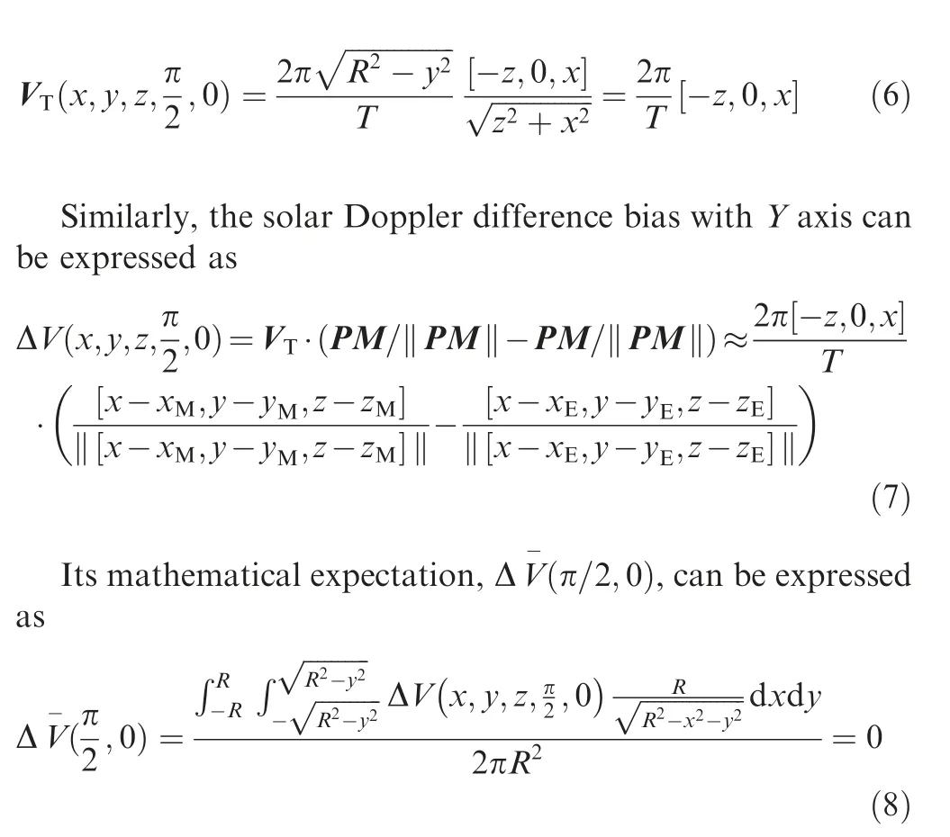
3.1. Solar rotation around Y axis
In this subsection, we investigate the solar Doppler difference biases with Y axis.The tangential velocity of the solar rotation at the point P can be given by Eq. (3) as
3.2. Solar rotation around Z axis
In this subsection, we investigate the solar Doppler difference biases with Z axis.The tangential velocity of the solar rotation at the point P can be given by Eq. (3) as

Similarly,the solar Doppler difference bias with Z axis can be expressed as

From the solar Doppler difference bias models with X,Y and Z axes, we can see that the direction of the solar rotation axis is an important factor.Due to the spacecraft orbital angle and the solar rotation axis drift,the direction of the solar rotation axis is not constant.Thus,it is necessary to build the solar difference bias model with arbitrary rotation axis.
4. Solar Doppler difference bias with arbitrary rotation axis
In the previous section, the solar Doppler difference biases with the coordinate axes are discussed.And the solar Doppler difference bias with arbitrary rotation axis is analyzed in this section.We investigate three variables in the solar Doppler difference bias: the distance from a point at the solar surface to the rotation axis, the direction of the solar rotation linear velocity at this point,and the difference between two direction vectors. And their product is the general model for the solar Doppler difference bias.
4.1. Distance
In this subsection, we investigate the distance from a point at the solar surface to the rotation axis. As shown in Fig. 3, the Sun rotates around one rotation axis. Let P (x, y, z) or P (θ,φ, r) be a point at the solar surface. We make the crosssection C perpendicular to the rotation axis through P and the origin. Let Q be the foot of perpendicular.
The point P at the surface of the Sun satisfies

Fig. 3 Solar rotation around arbitrary axis.

Assume that the point (xr, yr, zr) is the intersection of the rotation axis and the solar surface,and it can also be expressed as(θr,φr,r).The direction vector of the rotation axis is[xr,yr,zr].The line PQ is perpendicular to rotation axis.The foot of a perpendicular, Q (xq, yq, zq), satisfies the system of equations:

The solution to the system of equations is given by

Thus, the intersection point Q (txr, tyr, tzr) of the rotation axis with the plane C can be obtained.
The distance from the point P to the rotation axis is the length of the line segment PQ. Its expression is shown as

4.2. Direction vector
In the subsection, we investigate the solar rotation velocity direction [m, n, p] of the point P. The direction vector of PQ is [x-txr, y-tyr, z-tzr]. Assume that the vector perpendicular to PQ on the plane C is [m, n, p], and the system of Eq. (16)holds.

The following is a discussion on the classification of the p values:
It is not difficult to see that the direction[m,n,p]is perpendicular to the line PQ and the rotation axis,that is,the following equations is satisfied:

From Eqs. (16) and (17) can be simplified to

To make the cross product of[m,n,p]and[x-txr,y-tyr,ztzr] coincide with the direction of the rotation axis [xr, yr, zr],their dot product must be greater than 0. Combining with Eq. (18), we can get
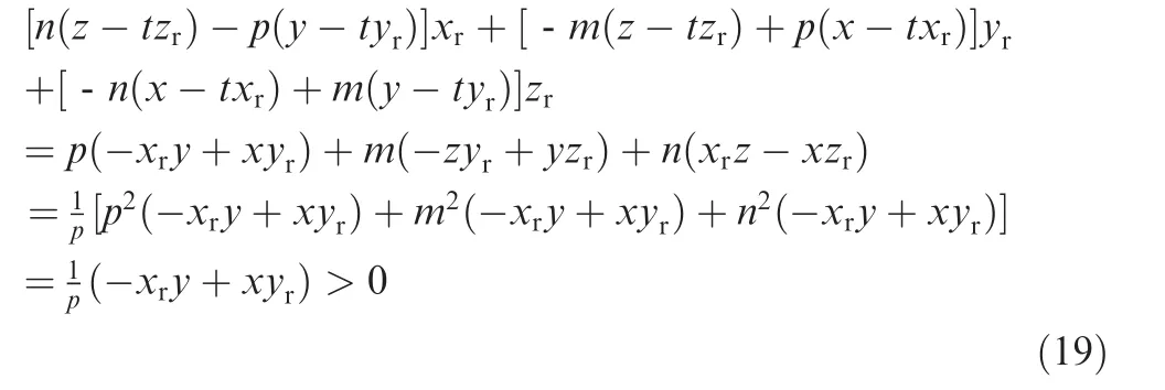
Thus, it can be divided into the following situations:
(1) By Eq. (19), we can obtain

Namely, p=0. Thus, it can be divided into the following situations:

This vector[m,n,0]is the direction of the solar rotation linear velocity at this point P, and then the solar Doppler difference velocity of the point P is

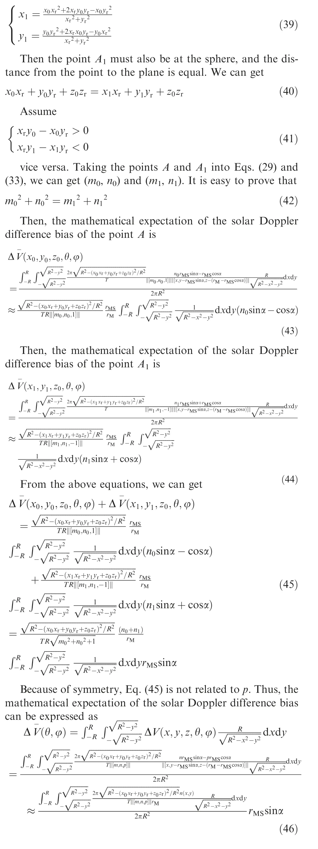
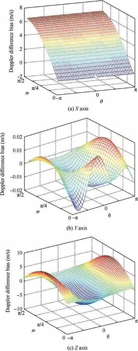
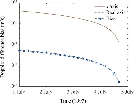
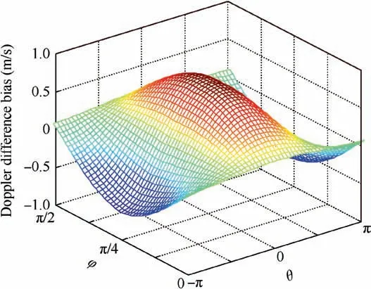
(C) If (a) and (b) conditions are not satisfied, and z The solar Doppler difference velocity of the point P is shown as where the sign function is to take the sign of a certain number(positive or negative). (D) If all of the above conditions are not satisfied, the values of m and n are as in Eq. (24), but (2) By Eq. (19), we can obtain Namely,p=1.Take p=1 into Eq.(16),and then Eq.(16)can be rewritten as This vector[m,n,1]is the direction of the solar rotation linear velocity at this point P, and then the solar Doppler difference velocity of the point P is (3) By Eq. (19), we can obtain This vector [m, n, -1] is the direction of the solar rotation linear velocity at this point P, and then the solar Doppler difference velocity of the point P is In the computational coordinate system, the coordinate of Mars is (xM, yM, zM) and the coordinate of the spacecraft is(xE, yE, zE), so the vector difference between the point P to Mars and the point P to the spacecraft is By combining the discussion in the first three subsections, the solar Doppler difference bias can be expressed as Combining these four subsections, we can summarize as follows: (1) The values are in accordance with Eq. (20), namely p=0, and it can be divided into the following situations: (a) If x =y=0 and xr=yr=0, the Doppler difference velocity of the point P is 0. (b) If only x =y=0, the values of m and n are in accordance with Eq. (21), and the Doppler difference velocity of the point P is in accordance with Eq. (22). (c)If(a)and(b)conditions are not satisfied,the values of m and n are in accordance with Eq.(24),and the Doppler difference velocity of the point P is in accordance with Eq. (25). (d)If all of the above conditions are not satisfied,the values of m and n are in accordance with Eq. (24), and the Doppler difference velocity of the point P is in accordance with Eq.(26). (2) The values are in accordance with Eq. (27), namely p=1. Then, the values of m and n are in accordance with Eq. (29), and the solar Doppler difference velocity of the point P is in accordance with Eq. (30). (3) The values are in accordance with Eq. (31), namely p=-1. Then, the values of m and n are in accordance with Eq. (33), and the solar Doppler difference velocity of the point P is in accordance with Eq. (34). Since the direction of the solar rotation cannot be determined,it is not a specific rotation around the X axis,the Y axis or the Z axis.For this purpose,the solar rotation Doppler difference bias model with arbitrary axis is established. In this section, we analyze the impacts of both the spacecraftto-Mars distance and the spacecraft-Mars-Sun angle. During the approach of the spacecraft to Mars,the position of the spacecraft relative to Mars is crucial and constantly changed. The relative position can be resolved into the spacecraft-Mars-Sun angle, α, and the spacecraft-to-Mars distance,rMS.Thus,the solar Doppler difference velocity model is discussed by using α and rMSas variables. Using α and rMSas variables, zM, yEand zEcan be expressed as Suppose that the symmetry point on the plane xry-xyr=0 of the point A(x0,y0,z0)at the sphere is A1(x1,y1,z0),and we can get As can be seen from the above equations,at a certain point on the sphere, the symmetry point about the plane xry-xyr=0 can always be found. Hence, the mathematical expectation of the solar Doppler difference bias Δ V-(θ,φ) is approximated as a sine function of the direction of the spacecraft relative to Mars, and a linear function of the distance between Mars and the spacecraft. Above results manifest that, when the spacecraft approaches Mars, the solar Doppler difference bias declines.This benefits from the improvement of accuracy in the approach phase. In this section, we investigate the effects of the solar rotation direction on the Doppler velocity difference. The simulation conditions are shown as follows: we take the American Mars Pathfinder as a reference, and the elements of its initial orbit are shown in Ref.30The orbital data of the Mars explorers and planets are generated by STK (Systems Tool Kit). The simulation time is 1 July 1997 00:00:00.000 UTCG as the approach phase of the Mars explorer is in this interval. We investigate the solar Doppler difference velocity biases with three coordinate axes as shown in Fig. 4. As shown in Fig.4,the wave surface profiles of the solar Doppler difference biases with three specific rotation axes are obviously different.Besides, compared with the solar Doppler difference biases of X and Z axes, the one of Y axis is smaller. When the solar rotation axis is Y or Z axis, the mathematical expectation of the bias is equal to zero. These results demonstrate that the direction of the solar self-rotation axis has a great impact on the solar Doppler difference bias. Therefore, it is necessary to establish the solar Doppler difference bias model with solar rotation around arbitrary axis. In previous section,it is found that,for different rotation axes,the wave surface profiles of the solar Doppler difference biases are different. It is difficult to present all wave surface profiles with all axes. Thus, in this section, we only investigate their mathematical expectation values. The mathematical expectations of the solar Doppler difference biases with all axes are shown in Fig. 5. In Fig. 5(a), for different directions of the rotation axes, the mathematical expectations of the solar Doppler difference biases are different.From Fig.5(b),we can see that the mathematical expectation of the solar Doppler difference bias is approximately cosinusoidal with respect to θ. With an increase of φ, the cosine amplitude decreases. When φ=π/2, the mathematical expectation of the bias constantly equals zero. When θ=π/2 or-π/2, the mathematical expectation of the bias constantly equals zero. Above results demonstrate that, when the solar rotation axis is Y or Z axis, the mathematical expectation of the bias is equal to zero. This is in good agreement with the theoretical analysis in Section 3 and the simulation results in Section 6.1. When φ=θ=0, the mathematical expectation of the bias reaches its maximum. This demonstrates that the mathematical expectation of the bias with X axis is the maximal.Besides,the wave surface profile is symmetric with respect to θ=0. Fig. 4 Solar Doppler difference bias with three specific rotation axes. In fact,the direction of the rotation axis of the Sun is relatively fixed, and its right ascension and declination are approximately 286.13° and 63.87° respectively31and the conversion to θ and φ is 6.01°and 4.59°respectively.In the computational coordinate system of this paper, the simulation is performed again with this rotation axis. The simulation time is 1 July 1997 00:00:00.000 UTCG as the approach phase of the Mars explorer is in this interval. The results are shown in Fig. 6. Fig. 5 Solar Doppler difference bias with all rotation axes. Fig. 6 Doppler difference bias of solar rotation. Fig. 7 Comparison of Doppler difference bias between rotation axis and X axis. Fig. 8 Doppler difference diagram of rotation axis and X axis. Table 1 Doppler difference between rotation axis and X axis. Fig. 9 Spacecraft-Mars-Sun angle vs Doppler difference bias. From Fig.7,we can see that,with the increase of the flight time, that is, as the spacecraft approaches to Mars, the Doppler difference bias of the solar rotation decreases with time.In the actual situation, the direction of the rotation axis of the Sun does not coincide with the X axis in the computational coordinate system,but there is a certain angle difference.In the actual situation, the solar Doppler difference bias wave with the real solar rotation axis is similar with that of the X axis as shown in Fig. 6. And their difference is presented in Fig. 8. The difference value is relative with the position at the solar surface. The difference of two biases is also shown in Table 1. The maximum difference is 0.692 m/s, the minimum difference is -0.683 m/s, and the expectation value of the overall difference is 0.054 m/s. This expectation value is not large, but the accumulation over time is also a high error.For Deep Space 1,the velocity accuracy of the celestial navigation system is approximately 0.2 m/s.32However, the maximum bias between two models is 0.7 m/s, and the average value is 0.05 m/s. Compared with 0.2 m/s, these values are not negligible.To make matters worse,the model bias is a constant.A small constant in the measurement estimation leads to the divergence of Kalman filter. It will affect the navigation accuracy, so the model-building of this article is meaningful. In the approach phase,the position of the spacecraft relative to Mars is crucial. In this paper, we investigate two factors including the spacecraft-Mars-Sun angle and the spacecraftto-Mars distance. Fig. 9 presents the solar Doppler difference bias vs.spacecraft-Mars-Sun angle. As can be seen from Figs. 9(a)-(e),for a spacecraft-Mars-Sun angle, the wave surface profile of the solar Doppler difference bias is not changed except for its amplitude. As shown in Fig. 9(f), the solar Doppler difference bias is approximately sinusoidal with the spacecraft-Mars-Sun angle, which is consistent with the property proved in Section 5. And the mean value of the solar Doppler difference bias is approximately 0, and the order of magnitude is 10-5m/s. Fig. 10 Doppler difference bias vs spacecraft-to-Mars distance. In actual situation, the spacecraft-Mars-Sun angle is commonly close to π/2. This leads to a large bias. Therefore, it is necessary to build the solar Doppler difference bias model. In the approach phase, the spacecraft-to-Mars distance reduces as time goes on.In this section,we investigate the solar Doppler difference bias vs. spacecraft-to-Mars distance. The simulation results are shown in Fig. 10. As can be seen from Figs.10(a)-(c),with an increase of the spacecraft-to-Mars distance, the wave surface profile of the solar Doppler difference velocity bias is not changed except for its amplitude. As shown in Fig. 10(d), the solar Doppler difference bias is approximately linear to the spacecraft-to-Mars distance, which is consistent with the property proved in Section 5.These results demonstrate that the solar Doppler difference bias decreases as time goes on. In fact, the importance of navigation information improves with time going on. Thus, this property is beneficial to obtain highly accurate navigation information at the end of the approach phase. In this subsection,the velocity caused by solar surface activity is considered as noise,and the influence of noise and its threeaxis components on solar Doppler differential bias is analyzed.To simplify the problem,the surface of the Sun is divided into2601 cells, and each cell sets a speed noise value. The solar Doppler difference bias is the result of the combined effects of these noises. Table 2 shows the relationship between the noise level and the solar Doppler difference bias without the solar rotation.As shown in Table 2,we can see that the X axis component has no effect on the solar Doppler difference bias;the effect of the Z axis component is negligible;the Y axis component plays a determining role. In addition, the noise level is almost directly proportional to the solar Doppler difference bias. In practice, the typical value of the small-scale solar surface activity velocity is 10 km/s, and the corresponding solar Doppler difference velocity bias is about 0.47 m/s. Compared with the bias (on the order of 1 m/s) caused by the rotation of the Sun,although this value is small,it still has a significant impact on the navigation system. In summary, the estimation of the Y-axis component of solar surface activity will be a problem worthy of study in the future. ? Fig. 11 Solar Doppler difference bias vs. direction variation of rotation axis. An error inevitably exits in the direction of the solar rotation axis. In this section, we investigate the impact of the direction error on the solar Doppler difference bias shown in Fig. 11.From Figs. 11(a)-(d), we can see that, for different directions of the rotation axes,the errors of the solar Doppler difference biases are different.Besides,the error of the solar Doppler difference bias has a linear relationship with the direction error,as shown in Fig.11(e).With the increase of the direction error of the rotation axis, the error of the solar Doppler difference bias increases. The wave surface profile of the solar Doppler difference bias is basically unchanged except for its amplitude. These simulation results mean that the small error is beneficial to the bias compensation.The model of the solar Doppler difference bias established above provides a reference for the bias compensation from its theoretical analysis and experimental simulation results. 7. Conclusions and prospect The solar Doppler difference navigation is an emerging promising celestial autonomous navigation method for approach phase. It makes full use of the relative frequency shift inversion speed between the direct solar spectrum and the planetary reflection spectrum. Besides, it provides highly accurate Doppler velocity information in the case of unstable solar spectrum.The navigation method is robust to solar spectral instability and has practical value. The rotation of the Sun causes the frequency shift of the two spectra. To compensate the frequency shift caused by the rotation, a universal solar Doppler difference bias model is established. By analyzing and simulating the properties of the model, the following conclusions are obtained: (A) the solar Doppler difference bias model also changes with the direction of the solar rotation axis;(B)compared with the traditional method, the solar Doppler difference bias model is closer to the actual situation; (C) the distance between the spacecraft and Mars is approximately proportional to the solar Doppler difference bias;(D)there is an approximate sinusoidal relationship between the direction of the spacecraft relative to Mars and the solar Doppler difference bias;(E)the solar Doppler difference bias decreases continuously during the approach phase. These results can provide reference for the design of the solar Doppler difference navigation system during the approach phase. The modelling of the solar Doppler difference bias is a challenging work. There are many interference factors that affect its model.The direction of the rotation axis is one of these factors. In future, we will analyze these factors such as the solar surface activity, the asteroid rotation and the inhomogeneous reflectivity. Acknowledgements This study was supported in part by the National Natural Science Foundation of China (Nos. 61873196, 61501336,61772187).


4.3. Vector difference

4.4. Bias model

5. Two properties of bias model

6. Simulation results
6.1. Three specific rotation axes
6.2. All rotation axes
6.3. Actual rotation axis




6.4. Spacecraft-Mars-Sun angle

6.5. Spacecraft-to-Mars distance
6.6. Noise interference


6.7. Direction error of rotation axis
杂志排行
CHINESE JOURNAL OF AERONAUTICS的其它文章
- Design and experimental study of a new flapping wing rotor micro aerial vehicle
- CFD/CSD-based flutter prediction method for experimental models in a transonic wind tunnel with porous wall
- Prediction of pilot workload in helicopter landing after one engine failure
- Study of riblet drag reduction for an infinite span wing with different sweep angles
- Modulation of driving signals in flow control over an airfoil with synthetic jet
- Strong interactions of incident shock wave with boundary layer along compression corner
