Physical model for acoustic resonance in annular cavity structure
2020-02-24FengtongZHAOMingsuiYANGXiodongJINGDeyouWANGYundongSHAYujinLIU
Fengtong ZHAO, Mingsui YANG, Xiodong JING, Deyou WANG,Yundong SHA, Yujin LIU
a School of Energy and Power Engineering, Beihang University, Beijing 100083, China
b Liaoning Province Key Laboratory of Advanced Measurement and Test Technology of Aviation Propulsion Systems,Shenyang Aerospace University, Shenyang 110136, China
c Shenyang Engine Research Institute of AECC, Shenyang 110015, China
KEYWORDS Acoustic resonance;Annular cavity structure;Large eddy simulation;Lighthill acoustic analogy;Multistage compressor
Abstract A physical model for acoustic resonance in the annular cavity structure is developed to represent the typical characteristic when acoustic resonance occurs. Firstly, the measurement of sound pressure in the casing and rotor blades vibration is operated in a multistage high pressure compressor. The sharp peak frequency and discrete multi-tone occur in the frequency spectrum of sound pressure in the compressor, and the vibration of the first stage of rotor blades synchronously presents the high amplitude. The frequencies associated with rotor blades vibration can be calculated with rotating sound source theory. It is also confirmed that acoustic resonance occurs in the multistage compressor. With acoustic similarity principle, an annular cavity model is established to simulate the typical characteristics of acoustic resonance in the compressor based on Large Eddy Simulation(LES)and Lighthill acoustic analogy.The coupling relationship between cavity acoustic mode and disc vibration mode shape is expounded when acoustic resonance occurs in the model. And acoustic resonance will be locked in the certain flow rate range. All these characteristics match well with those occur in the multistage high pressure compressor.
1. Introduction
Aeroengine compressor is a high-speed rotating turbomachinery, which usually works in high temperature and high pressure complex environments. Instability pressure disturbance which occurs in specific operating condition in aeroengine can induce rotor blades fracture, result in unbearable sound pressure level, and reduce the performance of aeroengine.Therefore, the strength of rotor blades is the focus of the areoengine development.1,2The high level vibration of rotor blades was detected on a ten stage compressor. The rotating instability was proposed as the noise source which excited the vibration of blades.3The blade tip flow instability excited the cavity acoustic mode and blades vibration occurred synchronously.4,5However, recent researches focused on the well known phenomenon of acoustic resonance.6,7Aeroengine components could be seriously endangered by significant acoustical excitation when acoustic resonance occurred.Sound frequencies induced by periodic vortex shedding of rotor blades were firstly investigated as the excitation of acoustic resonance in the compressor.8Systematic experiments were operated in a four stage compressor aiming at acoustic resonance.Several acoustic modes with equal frequency interval were obtained. The dominant acoustic mode of the sound pressure with a helical structure was cut-off, which were independent of the axial length in the compressor. And it could be confirmed that sound waves energy was trapped in the circumferential direction.9However, the characteristic of acoustic resonance was investigated only through experimental testings in above researches.
It is still impossible to simulate the whole aerodynamic pressure disturbance evolution with unsteady flow method in the multistage compressor for the unacceptable calculation cost. Therefore, the reasonably simplified physical model is necessary to investigate acoustic resonance in the compressor.The acoustic resonance model of flat cascade was first established by Parker.10-13Resonant sound waves occurred in the cascade when the natural frequency of the shedding vortex near the trailing edge of the flat plate is close to the natural frequency of acoustic mode. And the resonant waves fed back to the separate shear layer at the trailing edge,which would modulate the shedding vortex.Then the phenomenon of locked frequencies appeared which enhanced the energy exchange between sound field and flow. A new research direction and basic physical model were pioneered for the investigation of structural damage caused by acoustic resonance. A shedding vortex wake model for a two-dimensional rectangular plate was established.14The shear layer of the flow field was solved through numerical calculation in the model. The evolution process of the vortex wake was obtained over the time by introducing the weak perturbation at the initial stage of the shear layer.The calculated results were in good agreement with the experimental results. It was reported that the interaction mechanism between the flow wake of the flat plate and the acoustic resonance induced by the flow in the hard wall pipe was revealed. The acoustic resonance produced by the fluidinduced wake in the pipe was related to the thickness of the plate, the chord length, the shape of the trailing edge and the internal size of the rigid pipe.15With ignoring the air velocity and assuming the existence of Parker mode in the pipe,another prediction model of the shedding vortex was built.16-18The effect of sound waves on shedding vortices could be depicted qualitatively.And the frequency of the shedding vortex was locked on the frequency of the sound wave. An effective physics-based and simplified model was established in a four stage high speed compressor.19It was proposed that the incidence angle of sound wave in the blade row determined the transmission coefficient and reflection coefficient of the sound energy. In the model, it was assumed that the flow field vortex of the compressor was in the rigid body form, and the prediction of passing and cut-off conditions were considered.The acoustic resonance mechanism associated with discrete frequency peaks in the experiment was explained with that model.20A drive disk model for predicting acoustic resonance in aeroengine was developed based on the global stability theory.21It was presented that the acoustic resonance would occurred in the compressor when the rotor speed, Mach number of the flow vortex,mass flow and other parameters satisfied with specific combination conditions. Most of the above numerical models of acoustic resonance are based on onedimensional or two-dimensional models, and there are few studies on the coupling analysis between the acoustic mode and vibration mode.
It can conclude that the mechanism of acoustic resonance in the compressor is not revealed thoroughly. The influence of instability flow on the resonant sound field and the numerical model of acoustic resonance are still not established in the compressor. The physical model which can expound acousticstructure coupling when acoustic resonance occurs in the compressor is still under discussion. Therefore, there is not yet an effective design guideline for aeroengine structural design targeting acoustic resonance.It is the lack of such a capacity that motivated the authors to establish a physical model for acoustic resonance based on the experiment in the multistage compressor and the numerical calculation, which is the first attempt in open literature to investigate the interaction of the acoustic mode and vibration mode for multistage compressor with the three-dimensional model. Sound pressure with sharp peak frequency occurs in the multistage compressor simultaneously with high level vibration on the first stage of rotor blades which is confirmed as acoustic resonance. With acoustic similarity principle, an annular cavity model is established to simulate the typical characteristics of acoustic resonance in the compressor based on LES and Lighthill acoustic analogy. The coupling relationship between cavity acoustic mode and disc vibration mode shape is expounded when acoustic resonance occurs in the model. And the flow rate range where acoustic resonance appears is confirmed through the massive computation. All these characteristics match well with those occur in the multistage high pressure compressor. The results presented in this paper will provide effective support for structural design in the compressor.
2. Theory basis
2.1. Flow field simulation
The calculation of flow field characteristics in this paper includes the steady state and transient state. And Renormalization-group (RNG) k - ε turbulence model is adopted in the steady state. For the turbulence model, the small scale motion is systematically removed from the governing equation by embodying the influence of small scale motion on large scale motion and viscous motion. Equation k and ε can be expressed as

The key parameters in Eqs. (1) and (2) are

where ρ is the density of the media in the presence of acoustic disturbance.ui,ujare the velocity of the flow.Gkrepresents the turbulent kinetic energy generated by the laminar velocity gradient. τijis the flow viscosity stress tensor.
Compared with the standard k - ε model, the RNG k - ε model takes the rotating and swirling flow into account in the average flow by adding the term of turbulent viscosity.Eijis added into equation ε,which can reflect the time average strain rate of the mainstream. Therefore, the model is more applicable to the flow with high strain rate and large streamline curvature,which is suitable for the turbulence model with high Reynolds number.
For the transient flow field calculation, LES turbulence model is adopted in this paper. Firstly, the sub-lattice scale model of stress term is established. The N-S equation and the continuity equation under the instantaneous state of large vortex are obtained by removing vortices with smaller size than the filter.

where τijis the flow viscosity stress tensor. The terms with overbar in the above equations are the field variable after filtering.And in order to reflect the influence of the motion of small scale vortex group on the motion equation, Subgrid-scale Stress (SGS) can be expressed as

The stress term τijin Eq. (6) is unknown which need to be expressed by other physical quantities. And a basic model for SGS is

Combined Eqs.(4)-(8),the motion of vortex clusters in the cavity is solved by CFD method,and the flow field results can be obtained eventually.
2.2. Sound field calculation
Lighthill acoustic analogy method is adopted to extract the sound source from the calculation results of CFD in this paper. The continuity equation and the momentum equation are respectively expressed as

where p, v are the pressure and velocity of the media in the presence of acoustic disturbance. δijis the Kronecker symbol(i=j, δij=1; i ≠j, δij=0).
Under the condition of low Mach number, and based on the hypothesis of the small amplitude, with ignoring highorder terms above the second order, without considering entropy source and viscous stress, Lighthill stress tensor Tijcan be expressed as

Finally, Lighthill acoustic analogy can be written as

where ρais the density change caused by sound pressure. c0is the sound velocity outside the area of the sound source and the average flow.
Lighthill acoustic analogy is a combination of continuity equation and momentum conservation equation. Tijis an unknown quantity,which can be obtained by solving the complete N-S equation through flow field calculation. The flow field and the sound field are separated artificially in Lighthill acoustic analogy. The right hand side of Eq. (13) can be confirmed as the source,which obtained from the flow field calculation. And the left hand side is the typical acoustic wave equation. The sound source can be adopted from results of the flow field calculation by Lighthill acoustic analogy with sound wave Eq. (14) finally.
3. Experimental results
3.1. Testing parameters
The experiment is implemented in a multistage high speed compressor. The structural diagram of the compressor in the current experiment is shown in Fig. 1. The deflected angle of inlet guide vanes is adjusted to obtain various of inlet flow condition.The experiment is operated along the controlling curve of the compressor which matches well with the real operative condition of aeroengine. The parameters including rotor blades vibration,sound pressure in the casing and the rotating speed of rotor blades are monitored synchronously.Four measurement positions for sound pressure are chosen at the same circumferential direction and the different axial direction in the compressor(see Fig.1).Three mounting holes at circumferential position are selected for vibration status monitoring on the first stage of rotor blades (see Fig. 2).

Fig. 1 Structural diagram of compressor.

Fig. 2 Measurement positions of rotor blades vibration.
3.2. Frequency characteristic and mechanism
When the compressor is operated at various preset deflected angle for IGV and the first three stages of stators. The vibration of R1 is monitored at different rotor speeds. During the testing,the abnormal vibration of R1 occurs in the speed range about 9480 r/min to 10,560 r/min.Especially,when rotor speed reaches around 9960 r/min, the amplitude of rotor blades vibration increases sharply.During the testing,the sound pressure in the compressor is obtained with rotor blades vibration synchronously. When high level vibration occurs on R1, the time-domain wave of the sound pressure is transformed into frequency spectrum by Fast Fourier Transform. It is shown in Fig. 3. The frequency spectrum of the sound pressure with special frequency structure measured at different testing positions is obtained in a pre-arranged structure adjustment and specific rotor speed, which presents typical characteristic for discrete multi-tone when high level vibration occurs on R1.1BPF is the blade passing frequency of R1.And SF is a special characteristic frequency with the highest peak value. That means this characteristic frequency is the dominant component in the frequency spectrum.And the similarity of the wall pressure signatures in a low-pressure compressor which generated high sound pressure levels with a strong tonal component and a high pressure compressor which existed blade vibration problem were also reported.3,21

Fig. 3 Frequency spectrum of sound pressure measured above R1.
As shown in Fig. 4, a set of peak frequencies appear near the special characteristic frequency when high level rotor blades vibration occurs. And these frequencies are centered at the sharp peak frequency about 1410 Hz with equal interval about 166 Hz between different peaks which exactly matches with the rotor speed. It is clear that a hump occurs with combination and discrete frequencies. Relevant literature also mentioned and explained the specific frequency combination relationship.4,22Combining with the results in the previous research,7the propagation state of the characteristic frequency is a helix structure which presents the similarity status when acoustic resonance occurs.19The characteristic frequency appears on the sound pressure spectrum is just the typical characteristic of acoustic resonance.
Because the sound pressure wave in the compressor can be expressed differently with respect to different reference coordinates.3And the vibration frequency is about 746 Hz when high level vibration occurs on R1. Therefore, the frequency of the rotating sound source is evaluated as/2π=746 Hz in the source coordinate frame (S). According to the results in Fig. 4, in the fixed coordinate frame the rotating frequency of the rotating sound source can be set to=166 Hz.And the rotating sound source can modulate multiple acoustic modes with mode number α. Therefore, the frequency of the rotating sound source in the fixed coordinate frame (F)ωFRS/2π which measured in the casing can be calculated with the rotating sound source theory like relative literatures.3,7The calculated results are shown in Table 1.
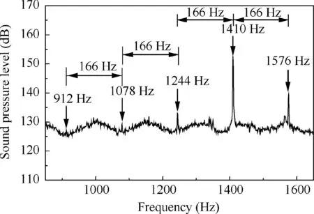
Fig. 4 Zoomed frequency spectrum of sound pressure.
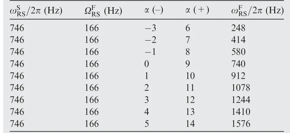
Table 1 Calculated results of rotating sound frequency.

Table 2 Dimension of flow numerical model.
Through the above analysis,it is found that the sharp peak frequency in Fig.4 can be calculated.Therefore,the excitation of the high amplitude vibration of R1 and the sharp peak frequency of sound pressure can be explained. In addition, other frequencies with different acoustic mode numbers shown in Table 2 are not presented obviously in Fig.3.This is probably relatived to the structural size in the compressor, which leads to the frequency cut-off at other acoustic modes. To prove the above conjecture, the circumferential mode distribution in the compressor need to be tested. And the amplitude and frequency of sound pressure should be captured in the rotor blade frame.Thereby,the investigation presented in this paper can be verified furtherly.
3.3. Acoustic resonance characteristic
It is shown in Section 3.2, when high amplitude vibration occurs on R1, the frequency spectrum of sound pressure with sharp peak frequency presents in the compressor at the same time. According to this, the relationship between sound pressure and rotor blades vibration is expounded in Fig. 5. It is expressed that once high amplitude vibration of rotor blades presents, the sharp frequency occurs simultaneously. The displacement amplitude of rotor blades vibration and the Sound Pressure Level (SPL) of the sharp peak frequency alter simultaneously, which reach the maximum level at the same time.The association between sound pressure and rotor blades vibration has been revealed in Section 3.2. Therefore, the source of the sharp peak frequency directly concerns with the vibration excitation of the first stage of rotor blades. So sound pressure with the sharp peak frequency in the compressor should be considered as a criterion for rotor blades vibration in this status.

Fig.5 Relationship between characteristic frequency and blades vibration.
When rotor speed of the compressor is pushed up from 9480 r/min to 10,560 r/min in a specific structural adjustment status, the evolution rhythm of the sharp peak frequency is presented in Fig. 6. It is clear that the sharp peak frequency about 1400 Hz is not the dominant discrete comment, but which is associated with the vibration of R1 according to the analysis in Section 3.2. Therefore, keep the focus on the sharp peak frequency. The amplitude of the sharp peak frequency will synchronously increase with the vibration of rotor blades.And this sharp peak frequency merely occur on the specific rotor speeds, which relates to structural adjustment of the compressor. The sharp peak frequency will be locked in a specific range presenting no variation with the rotor speed.In addition, as far as the author knows, when the sharp peak frequency occurs the vibration shape number of the first stage of rotor blades matches well with the acoustic mode number of the sharp peak frequency.All of these are recognized as typical characteristics when acoustic resonance occurs. It also can conclude that the inlet flow state in the compressor will be an important factor for the cause of the frequency (Fig. 7).
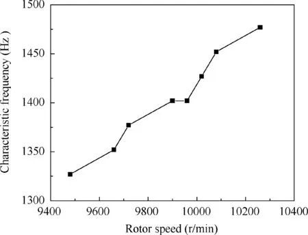
Fig. 7 Locked-in of characteristic frequency with rotor speed.
4. Physical model for acoustic resonance
4.1. Geometric dimension and numerical model
Due to the complex geometry of the compressor,it is very difficult to directly calculate the resonant response of the cavity structure under the coupling status of the flow field,sound field and structure.Therefore,it is very necessary to establish a simplified physical model. According to the results of the above testing, the characteristic of following and locked between the frequency in acoustic resonance and rotor speed, as well as the coupling relationship between acoustic mode and structural vibration mode will appear when acoustic resonance occurs in the compressor.The high pressure compressor is simplified into a annular cavity structure based on acoustic similarity principle. Schematic diagram of the annular cavity structure is shown in Fig. 8. The annular cavity structure is formed by connecting two thin-wall discs with the hub in the circular pipe, according to the cavity structure between rotors and adjacent stators in the compressor.

Fig. 8 Schematic diagram of annular cavity structure.
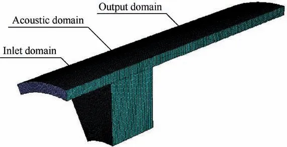
Fig. 9 Flow numerical model.
According to the structural characteristic of Fig. 8, the computational domain is divided into three parts about inlet domain,acoustic domain and outlet domain(see Fig.9).Based on the principle of ensuring the full development of the flow field,the length of inlet domain and outlet domain are reasonably selected by considering the calculation amount. The dimension of acoustic domain is constituted by the clearance,the length and the depth of the cavity.The detailed dimensions of each part of the flow field calculation model are shown in Table 2. On the premise of no affecting the accuracy of the flow field calculation, the periodic boundary with the extraction 30° region is adopted in the flow numerical model to improve the calculation efficiency. Structured mesh is chosen with the maximum mesh size of 1.2 mm. The total number of meshes is about 700000.Firstly,steady state status is calculated to initialize the flow field. In the steady state, the input condition is the inlet flow velocity. RNG k - ε model and the standard wall function are chosen. SIMPLEC (Semi-Implicit Method for Pressure Linked Equation Consistent) algorithm is used to solve the pressure equation with 200 iterations.The treatment of boundary layer is very critical. According to the standard wall function, the value of Y+is reasonably selected based on the empirical formula. And the flow condition in the boundary layer can be calculated with the date of the core region. On this basis, transient state status is calculated with LES method.And in the transient state,PISO(Pressure Implicit Split Operator) algorithm is used to solve the pressure equation. The sampling frequency should be more than two times of the signal frequency according to the sampling theorem. In order to obtain the sound source information within 3000 Hz, the time step in the transient calculation is set as 0.000167 and the time step number is 600.
On the basis of the flow field calculation, sound source is extracted from the flow field with Lighthill sound analogy method. Thereby, the sound pressure induced by flow in the annular cavity structure can be calculated.In order to simulate free field conditions, two hemispherical regions with the infinite element boundary are added to both sides of acoustic domain (see Fig. 10). And the maximum mesh size is 20 mm.In order to effectively distinguish all sound waves within 3000 Hz, the maximum mesh size of the acoustic domain is set as 8 mm based on the principle of distinguishing one wavelength with 8 grids.The maximum mesh size of the disc is also set as 8 mm to investigate the vibration response of the disc under the sound pressure induced by flow (Fig. 11).
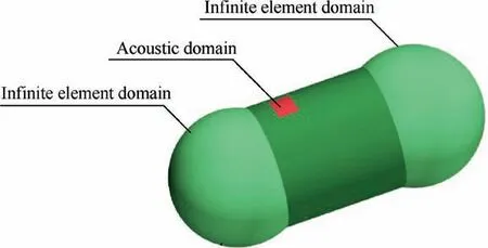
Fig. 10 Acoustic numerical model.

Fig. 11 Sound pressure spectrum in cavity structure.
4.2. Response analysis of cavity under monopole
The acoustic mode in the cavity of the annular cavity structure is obtained by sweeping frequency excitation with a monopole sound source of 1 Pa. The sound pressure spectrum response of the cavity structure is shown in Fig. 10.
According to the result of sound pressure spectrum in the annular cavity structure under the excitation condition of monopole sound source, the first three orders acoustic mode frequencies in the structure are 1130 Hz, 1960 Hz and 2770 Hz respectively. Therefore, the phenomenon of acoustic resonance will occur in the structure when the natural vibration frequency of the disc matches with the acoustic mode frequency in the cavity. Therefore, the disc of the annular cavity structure is designed with the natural vibration frequency of 1130 Hz. And the detailed geometric dimension and physical property of the disc are presented in Table 3. The nephogram of sound pressure response and the disc vibration displacement of the designed annular cavity structure excited by monopole sound source are shown in Fig. 12. The status of acoustic resonance in the structure is shown in Table 4.
In Fig. 12, the first order frequency of acoustic mode is close to the natural frequency of disc vibration.The frequency resolution of the calculation is 10 Hz, which is reason for the frequency difference here. And the acoustic mode number of this frequency is consistent with the vibration shape of the disc.Therefore, It can be judged that acoustic resonance is excited in the annular cavity structure with this geometric condition.It is also confirmed that the occurrence condition of acoustic resonance is not only that the vibration frequency of the structure should be consistent with the acoustic mode frequency of the cavity, but also that the mode number coupling should be satisfied.

Table 3 Dimension and physical property of disc.

Fig. 12 Cavity acoustic mode and disc vibration mode under monopole sound source.

Table 4 Acoustic resonance status in annular cavity structure under monopole sound source.
4.3. Acoustic resonance analysis
Vibration displacement response of the disc and sound pressure in the cavity are calculated with the annular cavity structure confirmed above under different inlet flow conditions.The flow range when acoustic resonance occurs in the annular cavity structure is obtained through massive computations. The sound pressure spectrum response in the cavity of the structure under different inlet flow conditions is shown in Fig. 13. The nephograms of sound pressure response and disc vibration displacement of the structure under different inlet flow conditions are shown in Fig. 14. The status of acoustic resonance in the structure is shown in Table 5.

Fig. 13 Sound pressure spectrum in the cavity structure under different inlet velocities.

Fig. 14 Cavity acoustic mode and disc vibration mode at different frequency and inlet velocity.
From Fig.14,it is clear that the acoustic mode in the cavity can be excited in the various of inlet velocities. The acoustic mode frequency of the cavity and the vibration frequency of the disc are about 1119 Hz, 1129 Hz and 1139 Hz. The acoustic mode number of the cavity is about 2, and the vibration shape number of the disc is also about 2 except in Fig. 14(d).Therefore, the phenomena of the coupling between cavity acoustic mode and disc vibration mode shape will present in several inlet velocities.The frequency resolution of the calculation is 10 Hz,which is also the reason for the frequency difference here.Under different inlet flow conditions,the occurrence condition of acoustic resonance is still that the vibration frequency of the structure should be consistent with the acoustic mode frequency of the cavity, and the mode number coupling should be satisfied meanwhile, which is consistent with the results under monopole sound source. It can be concluded from Fig. 15 that acoustic resonance will be locked in the certain flow rate range,which match well with characteristic when acoustic resonance occurs in the multistage high pressure compressor. However, there is the difference that no frequency modulation occurs in acoustic resonance frequency in the annular cavity model.

Fig. 14 (continued)

Fig. 14 (continued)

Fig. 15 Locked-in of characteristic frequency with flow speed.
5. Conclusions
In this investigation,the measurement of sound pressure in the casing and rotor blades vibration is operated in a multistage high pressure compressor. The sharp peak frequency and discrete multi-tone occur in the frequency spectrum of sound pressure in the compressor, and the vibration of the first stageof rotor blades synchronously presents the high amplitude.The displacement amplitude of rotor blades vibration and the SPL of the sharp peak frequency alter simultaneously,and which reach the maximum level at the same time.

Table 5 Acoustic resonance status in annular cavity structure under different inlet velocities.
The sharp peak frequency will be locked in a specific range presenting no variation with the rotor speed, which confirmed as the typical characteristic when acoustic resonance occurs.And it is also confirmed that acoustic resonance occurs in the multistage compressor. The acoustic resonance frequency and its side-band frequencies modulated by a rotating sound source can be calculated through the frequency transformation at different coordinate systems. And the acoustic resonance frequency can be confirmed as the excitation source of the first stage of rotor blades vibration.
With acoustic similarity principle, an annular cavity model is established to simulate the typical characteristic of acoustic resonance in the compressor based on LES and Lighthill acoustic analogy. The coupling relationship between cavity acoustic mode and disc vibration mode shape is expounded when acoustic resonance occurs in the model. And acoustic resonance will be locked in the certain flow rate range. All these characteristics match well with those occur in the multistage high pressure compressor.
Acknowledgements
This research was co-supported by the Liaoning Natural Science Foundation Guiding Plan of China (No. 2019-ZD-0237), and the National Science Foundation of China (Nos.51576009, 11661141020 51711530036).
杂志排行
CHINESE JOURNAL OF AERONAUTICS的其它文章
- Design and experimental study of a new flapping wing rotor micro aerial vehicle
- CFD/CSD-based flutter prediction method for experimental models in a transonic wind tunnel with porous wall
- Prediction of pilot workload in helicopter landing after one engine failure
- Study of riblet drag reduction for an infinite span wing with different sweep angles
- Modulation of driving signals in flow control over an airfoil with synthetic jet
- Strong interactions of incident shock wave with boundary layer along compression corner
