Theoretical study of ullage washing with mixed inert gas in a non-equilibrium state
2020-02-24ShiyuFENGXiotinPENGLeiSHAOYnYANChenCHENWeihuLIU
Shiyu FENG, Xiotin PENG,*, Lei SHAO, Yn YAN, Chen CHEN,Weihu LIU
a Key Laboratory of Aircraft Environment Control and Life Support of MIIT, College of Aerospace Engineering, Nanjing University of Aeronautics and Astronautics, Nanjing 210016, China
b College of Aeronautics, Chongqing Jiaotong University, Chongqing 400074, China
c College of Mechanical and Electrical Engineering, Xi’an Polytechnic University, Xi’an 710000, China
KEYWORDS Inert gas;Mixed inert gas;Nitrogen enriched air;Non-equilibrium;Washing
Abstract The Mixed Inert Gas (MIG) produced by the novel Green OnBoard Inerting Gas Generation System(GOBIGGS)mainly consists of carbon dioxide,nitrogen and oxygen.Because of the large solubility of carbon dioxide in jet fuel compared with nitrogen, the no gas release or equilibrium model could not be employed any more. In this paper, first, a mathematical model of the ullage washing was set up to predict the variation of the oxygen concentration on ullage and in the fuel, and the gas evolution and dissolution rate were calculated by Fick’s second law. Then,an experimental apparatus was constructed to verify the accuracy of the model.Finally,the numerical comparisons of ullage washing using Nitrogen Enriched Air (NEA) and MIG are presented under various flow rates and fuel loads,and the result reveals that the variation of the oxygen concentration on ullage is nearly identical whatever the inert gas is NEA or MIG. However, the variation of the oxygen concentration in the fuel is disparate, and the oxygen concentration decreases rapidly if the inert gas is MIG,especially when the fuel load is low or the flow rate of the inert gas is high.Besides,MIG could suppress the rising trend of the oxygen concentration on ullage when the aircraft ascends if the fuel tank is fully washed into an equilibrium state on ground.
1. Introduction
Air crash data covering a span of approximately 50 years reveal that fires and explosions of the fuel tank have become the major causes of crashes.1,2The aircraft fuel tank inerting technology using an injection of Nitrogen Enriched Air(NEA) into the fuel tank is the most widely used technology for preventing such events. NEA is produced by an Air Separation Module (ASM) of an OnBoard Inerting Gas Generation System (OBIGGS), which is made of hollow fiber membranes.3-6Unfortunately, there are inherent disadvantages of this technology, such as the low efficiency of the hollow fiber membranes, which leads to a large fuel penalty; the high pressure requirement of the inlet of the hollow fiber membrane,which results in the incapability of its use in many aircraft(such as helicopters); the small fiber membrane and pore size,which causes blockages; the ozone in the bleed air, which degrades the fiber membrane performance; the displaced and discharged fuel vapor, which pollutes the environment.7-9
Nomenclature
c molar concentration
t time
m mass
p pressure
x, y coordinate
D diffusion coefficient
M molar mass
R ideal gas constant
T temperature
V volume
˙m mass flow rate
β Ostwald coefficient
Subscripts
t total
C carbon dioxide
F fuel-phase
N nitrogen
O oxygen
U ullage
Many researchers have begun to study new onboard inerting technologies because of these disadvantages of the OBIGGS. The Green OnBoard Inerting Gas Generation System(GOBIGGS)has attracted considerable attention in recent years because of its simple process, high efficiency, compact size, and light weight.10-12The basic principle of the GOBIGGS is derived from the flameless combustion of air and fuel vapor in the fuel tank ullage through a catalytic reactor. After the water vapor is removed in the separator, the remaining Mixed Inert Gas (MIG), which consists of carbon dioxide, nitrogen and oxygen, is reinjected into the fuel tank ullage,which gradually reduces the oxygen concentration until it reaches below the flammability level, providing the maximum safety margin.
Air readily dissolves in fuel, in which the solubility of oxygen is considerably higher than that of nitrogen. Thus, fuel contains a larger percentage of oxygen by volume than air.The solubility can be calculated using the Ostwald coefficient.The oxygen concentration in fuel is approximately 37%at sea level. When an aircraft ascends to altitude, the pressure in the fuel tank ullage decreases and the dissolved gases will evolve from the fuel until the partial pressures of the oxygen and nitrogen between the fuel and ullage are equal, resulting in an increase in the ullage oxygen concentration due to the smaller solubility of nitrogen.Many studies have been conducted to determine the influence of oxygen evolution on the inerting system.For example,Grenich et al.13established a mathematical model to estimate the quantity of oxygen evolution based on equilibrium theory. McConnell et al.14employed an equilibrium model to simulate the fuel scrubbing process.Cavage15applied a numerical calculation method to compare the equilibrium model with the no gas release model and found that the oxygen concentrations of the two models can be used as the upper and lower limits,respectively.Harris and Ratcliffe16adopted dimensional modeling of fuel outgassing to estimate the mass release rate of oxygen within an A320 aircraft fuel tank. The phenomenon of gas evolution in ullage washing is generally estimated according to the equilibrium or no gas release model.
The aforementioned studies are based on the OBIGGS technology, in which the inert gas is NEA. However, in the GOBIGGS, the MIG contains carbon dioxide, whose solubility in fuel is considerably higher than that of nitrogen or oxygen. In general, the solubility of carbon dioxide is approximately 9 and 21 times higher than that of oxygen and nitrogen, respectively, in a Jet A.17If the equilibrium or no gas release model is still used to estimate oxygen concentration in an ullage,an unexpected error occurs,and thus a more effective mathematical model must be established.
In essence, the dissolution and evolution of gas is a mass transfer process in a non-equilibrium state. When there is a gas concentration gradient in the fuel, the mass transfer that is produced by the thermal motion of the molecules will continue until the gas concentration reaches uniformity. Fick’s second law is widely used to describe the process of gas dissolution in the petroleum and chemical industries. For instance,Li18-20and Civan21et al. established mathematical models to describe the mass transfer process of carbon dioxide and methane in hydrocarbon liquid based on different assumptions.

Fig. 1 Schematic diagram of non-equilibrium state ullage washing model.
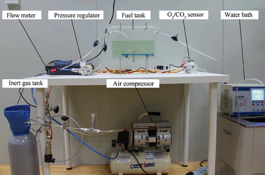
Fig. 3 Experimental system.
Based on Fick’s second law, this study established a twodimensional mathematical model of ullage washing in a nonequilibrium state and verified the accuracy of the model through an ullage washing experiment. On this basis, this paper analyzes the variation of the ullage and dissolved oxygen concentration for different fuel loads and flow rates.
2. Non-equilibrium state ullage washing model
The ullage washing process, as shown in Fig. 1, is modeled with the following simplifications and essential assumptions:

Fig. 4 Calibration of O2/CO2 sensor.
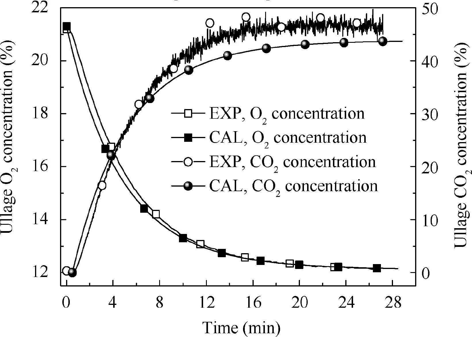
Fig. 5 Comparison of calculation and experimental results under 33.3% fuel load, 0.3 L/min flow rate and 12% oxygen concentration.
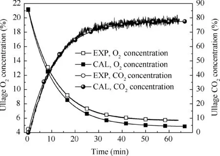
Fig. 6 Comparison of calculation and experimental results under 50% fuel load, 0.1 L/min flow rate and 5% oxygen concentration.
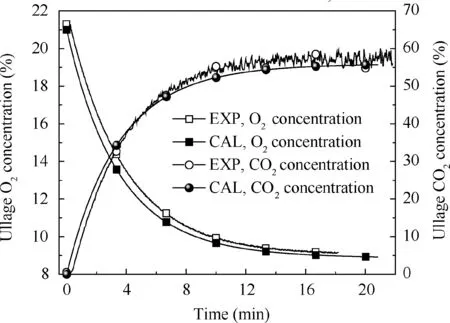
Fig. 7 Comparison of calculation and experimental results under 66.7% fuel load, 0.2 L/min flow rate and 9% oxygen concentration.

Table 1 Experimental equipment and parameters.

Table 2 Experimental conditions.
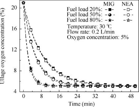
Fig.8 Comparison of ullage oxygen concentration over time for different fuel loads using MIG and NEA.

Fig.9 Comparison of ullage oxygen concentration over time for different flow rates using MIG and NEA.
(1) There is perfect mixing at any time for the gas,and there is no pressure gradient in the gas phase.
(2) Evaporation of fuel into the gas phase is negligible. The width of the fuel tank is 1 m.
(3) The temperature of the gas and fuel phases is equal and remains constant, TU=TF.
(4) Resistance of the mass transfer at the gas/fuel interface can be neglected, the concentration at the interface is the equilibrium concentration, and the dissolved gas at the interface can be calculated according to the Ostwald coefficient.
(5) The fractional proportions of O2, N2and CO2of the outflow equal the gas phase.
At an infinitesimal time interval dt,the respective mass conservation equations of O2, N2and CO2in the ullage are
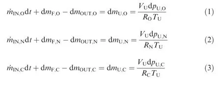
where the mass flow rates of O2,N2and CO2are ˙mIN,O, ˙mIN,Nand ˙mIN,C,respectively,and the mass variations of O2,N2and CO2in the fuel are dmF,O,dmF,Nand dmF,C,respectively.The masses of O2, N2and CO2that flow out of the fuel tank are dmOUT,O, dmOUT,Nand dmOUT,C, respectively. The mass variations of O2,N2and CO2on the ullage are dmU,O,dmU,Nand dmU,C,respectively.VUis the volume of the fuel tank ullage in m3.TUis the temperature of the fuel tank ullage in K.RO,RNand RCare the individual gas constants in J/(kg·K), and pU,O,pU,Nand pU,Care the partial pressures in the gas phase in Pa.
To obtain precise solutions of dmF,O,dmF,Nand dmF,C,the gas diffusion into the fuel can be modeled by Fick’s second law as
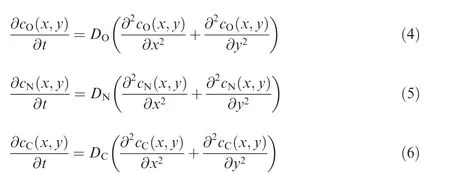
where DO, DNand DCare the diffusion coefficients of O2,N2and CO2, in m2/s, respectively18; cO, cNand cCare the molar concentrations of O2, N2and CO2, in mol/m2,respectively.
The boundary conditions applicable to this model are given by
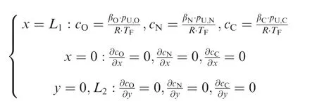
where βO,βNand βCare the Ostwald coefficients of O2,N2and CO2,respectively22;R is the ideal gas constant.The initial gas molar concentration in the fuel phase is assumed to be in equilibrium with the air, and the molar concentration of the gas/fuel interface varies with the gas partial pressure during the ullage washing.
The masses of dissolved O2, N2and CO2are as follows:

where MO, MNand MCare the molar masses of O2, N2and CO2, in kg/mol, respectively. VFis the volume of the fuel in m3.
The total pressure in the ullage is the sum of the partial pressures of O2, N2and CO2, and thus

The fractional proportions of O2, N2and CO2of the outflow equal the gas phase; therefore

The resulting variation of the partial pressures of O2, N2and CO2in the ullage can be determined as

When βO, βNand βCare taken as 0, there are no dissolved gases in the fuel.Therefore,the model converts into the no gas release model. When ˙mIN,Cis taken as 0, indicating that the inert gas does not contain CO2, the model converts into an NEA washing model.
According to the established mathematical model,the noncausal modeling language Modelica is used to program and solve.
3. Experiment and model validation
3.1. Experimental setup and calibration
A fuel tank ullage washing apparatus was constructed,and its flowchart is shown in Fig. 2.
A rectangular fuel tank with dimensions of 250 mm×50 mm×180 mm (L×W×D) is employed, the jet fuel is RP-3, and the ambient temperature is 30°C. The experimental instruments include a high-pressure CO2/N2cylinder, inert gas tank, pressure transducer (HSTL-800), vacuum pump (FY-1H-N), air compressor, pressure regulator(IR2000-02), O2and CO2concentration sensor (MAX250B,COZIR-W), water bath (DC-8030), condensing coil, and oil separator.The parameters and accuracy of the instruments utilized in the experiment are shown in Table 1.The experimental system is shown in Fig. 3.
Each experiment consists of three steps: the preparation of the MIG, ullage washing, and fuel scrubbing using air.
(1) First, the inert gas tank is evacuated with a vacuum pump and then filled with a specific proportion of air and CO2using the air compressor and the CO2highpressure gas cylinder.
(2) After the pressure reading in the inert gas tank stabilizes,the F2 and F3 shut-off valves are opened and the flow rate is controlled to a specified value by adjusting the throttle. Then, MIG is directly introduced into the ullage to vent the ullage air out of the fuel tank, and the outflow goes through the condenser and oil separator and then flows into the O2/CO2measurement device.
(3) After reading the data, the bottom of the fuel tank is connected to the air compressor and the air is used to scrub the fuel to remove the inert gas followed by the preparation for the next experiment.
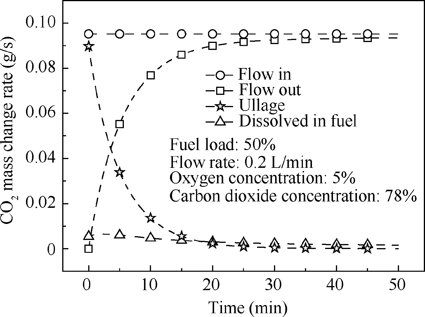
Fig. 10 Mass change rate of CO2.

Fig. 11 Comparison of fuel-phase oxygen concentration over time for different fuel loads using MIG and NEA.
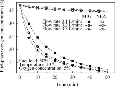
Fig. 12 Comparison of fuel-phase oxygen concentration over time for different flow rates using MIG and NEA.
The O2sensor and CO2sensor are calibrated by sample gases before they are actually used. The CO2concentrations are 0%, 39% and 71%, whereas the O2concentrations are 0%,7.3%,10.8%and 21%.The calibration results are plotted in Fig. 4. The maximum deviation is within 5% for the CO2sensor and 0.7%for the O2sensor,indicating that the accuracy of the sensors is acceptable.
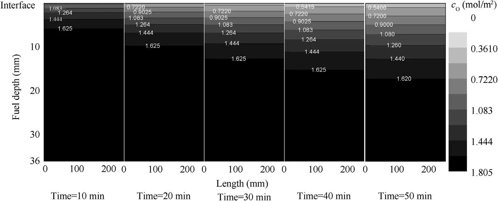
Fig. 13 O2 molar concentration.

Fig. 14 N2 molar concentration.
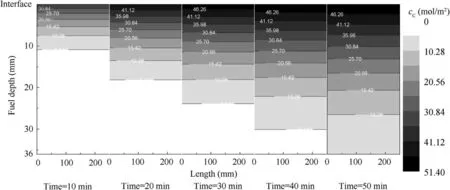
Fig. 15 CO2 molar concentration.
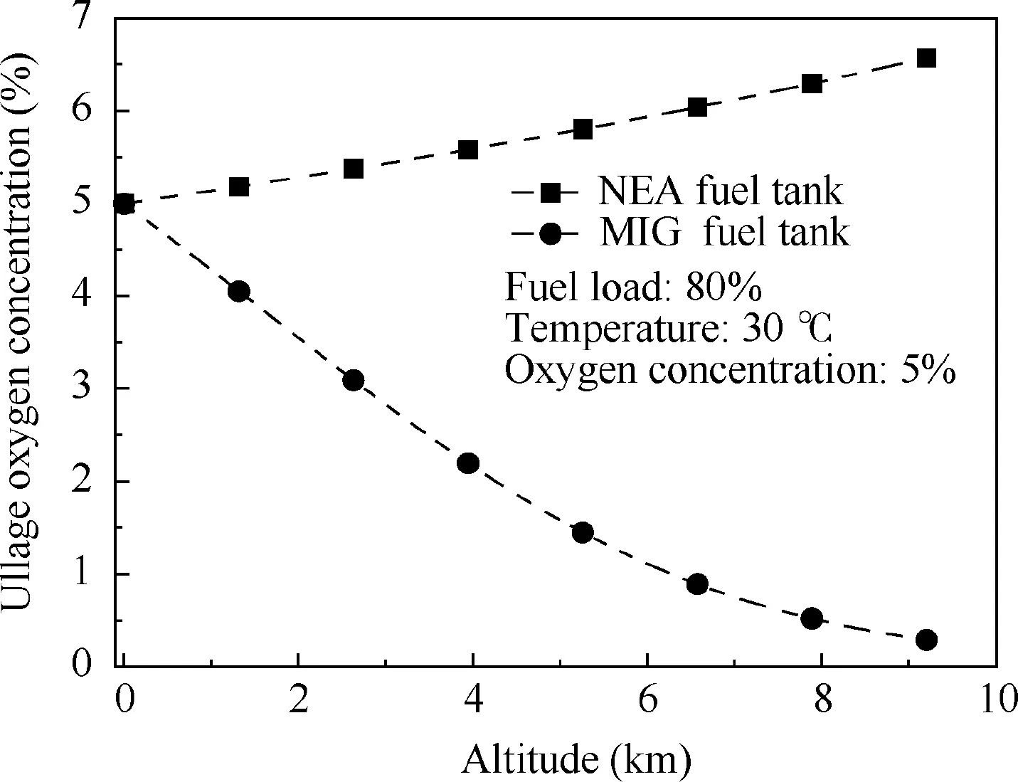
Fig.16 Relationship between equilibrium oxygen concentration and altitude.
3.2. Model validation
Three different experimental conditions were adopted in this study, as shown in Table 2.
Figs. 5-7 illustrate the calculated and measured average ullage oxygen concentrations for different conditions. The mean errors of the oxygen and CO2concentrations between the experimental results and calculation are less than 1%and 4%,respectively,indicating that the non-equilibrium state ullage washing model can be used for further analysis.
4. Results and analysis
The NEA with a 5%oxygen concentration and the MIG with 5% oxygen concentration and 78% CO2concentration are adopted for fuel loads of 20%, 50% and 80% and flow rates of 0.1,0.2 and 0.3 L/min,respectively.The effect on the ullage oxygen concentration is illustrated in Figs. 8 and 9. When using the same oxygen concentration for NEA and MIG, the ullage oxygen concentration curves are not significantly different,with a maximum ullage oxygen concentration difference of only 0.4%. To investigate this phenomenon, the mass change rate of CO2, including the ullage and the fuel phase and the outlet, was calculated in a different location with 50% fuel load and 0.2 L/min flow rate. The results are shown in Fig. 10. In the ullage washing process, the majority of the CO2remains in the ullage or directly flows out, with only a small quantity of the CO2dissolved in the fuel.Thus,for ullage washing on the ground, using MIG or NEA with the same oxygen concentration will have only a slight effect on the ullage oxygen concentration and can thus be neglected in the majority of cases.
However, under the same operational conditions, the fuelphase oxygen concentration has a considerable effect when using MIG or NEA to wash the fuel tank.Figs.11 and 12 illustrate that, for the fuel tank washed by NEA, the fuel-phase oxygen concentration exhibits minor changes under different fuel loads and flow rates.Even at a fuel load of 20%,the maximum fuel-phase oxygen concentration decrease is less than 5%. The main reason for this small change is that O2and N2are rather insoluble in the fuel and the gas evolution from the fuel is slow,resulting in a minimal impact on the fuel-phase oxygen concentration. This conclusion is consistent with the experimental results presented in Ref.23However,when using MIG to wash the fuel tank, the fuel-phase oxygen concentration decrease is more than 20% because CO2is considerably more soluble in the fuel than O2and N2.In addition,CO2dissolves more rapidly in fuel, thus rapidly increasing the CO2molar concentration in the fuel while rapidly decreasing the oxygen concentration by volume in the fuel. Figs. 13-15 show the molar concentration distributions of O2,N2and CO2over time at 20% fuel load and 0.2 L/min flow rate. The initial molar concentrations of O2and N2in the fuel are approximately 1.8 and 3.1 mol/m2respectively,which is in equilibrium with air. Additionally, the O2and N2molar concentrations decrease over time from the gas/fuel interface, but the CO2molar concentration increases over time and the CO2molar concentration is considerably higher than those of O2and N2. This illustrates the reason for the rapid decrease in the fuel-phase oxygen concentration.
Additionally,Fig.11 shows that the fuel-phase oxygen concentration at 20%fuel load is considerably lower than those at 50% and 80% fuel loads at a given time. This trend occurs because the transfer driving force produced by the concentration gradient is insufficient at greater fuel depths when the fuel load increases. The effect of the flow rate on the fuel-phase oxygen concentration is presented in Fig. 12. The fuel-phase oxygen concentration tends to decrease with the increase in the flow rate due to an increasing imbalance between the gas and fuel.
When using MIG to wash the fuel tank, the CO2dissolves into the fuel, causing a decrease in the fuel-phase oxygen concentration and changing the state of gas evolution. To study the influence on gas evolution, NEA (5%O2) and MIG (5%O2and 78%CO2)are used to inert the fuel tank to equilibrium,and the equilibrium theory presented in Ref.15is used to calculate the equilibrium oxygen concentration,which varies with altitude, as shown in Fig. 16. For the fuel tank washed by NEA, the oxygen concentration increases with altitude. This trend occurs because when the total pressure of the fuel tank varies with altitude, the equilibrium between the gas and fuel phases is disrupted,causing the oxygen and nitrogen to escape from the fuel. Because the solubility of oxygen is greater than that of nitrogen,the evolution of oxygen is greater than that of nitrogen,resulting in the gradual increase in the ullage oxygen concentration with altitude. This result is consistent with the experiments conducted by Parker-hannifin Corp.24However,for the fuel tank washed by MIG,the equilibrium oxygen concentration tends to decrease because the solubility of CO2is considerably higher than those of oxygen and nitrogen, and considerably more CO2evolves than oxygen and nitrogen;hence the ullage oxygen concentration gradually decreases.Therefore, the increase in the fuel-phase CO2concentration can restrain the negative trend of the increase in the ullage oxygen concentration when the aircraft ascends,providing a larger safety margin.
5. Conclusions
(1) For ullage washing on the ground, using MIG or NEA of the same oxygen concentration will have only a slight effect on the ullage oxygen concentration and can thus be neglected in the majority of cases.
(2) When washing the ullage with MIG,the fuel-phase oxygen concentration decreases rapidly, and the lower fuel load and higher flow rate result in a rapid decrease in the fuel-phase oxygen concentration. When washing the ullage using NEA, the effect of oxygen evolution on the fuel-phase oxygen concentration can be neglected. In addition, if the mass transfer process is considered, the prediction of the oxygen concentration could be more accurate when the airplane takes off.
(3) Generally, using MIG to inert the fuel tank can restrict the negative trend of the increase in the ullage oxygen concentration when the aircraft ascends.
Acknowledgements
This work was supported by National Natural Science Foundation of China Civil Aviation Joint Fund(No.U1933121),Postgraduate Research & Practice Innovation Program of Jiangsu Province (No. KYCX19_0198), the Fundamental Research Funds for the Central Universities and Priority Academic Program Development of Jiangsu Higher Education Institutions.
杂志排行
CHINESE JOURNAL OF AERONAUTICS的其它文章
- Design and experimental study of a new flapping wing rotor micro aerial vehicle
- CFD/CSD-based flutter prediction method for experimental models in a transonic wind tunnel with porous wall
- Prediction of pilot workload in helicopter landing after one engine failure
- Study of riblet drag reduction for an infinite span wing with different sweep angles
- Modulation of driving signals in flow control over an airfoil with synthetic jet
- Strong interactions of incident shock wave with boundary layer along compression corner