Improved local amplification factor transport equation for stationary crossflow instability in subsonic and transonic flows
2020-02-24JikunXULeiQIAOJunqingBAI
Jikun XU, Lei QIAO, Junqing BAI
a School of Aeronautics, Northwestern Polytechnical University, Xi’an 710072, China
b Department of Mathematics, Imperial College London, London SW7 2AZ, United Kingdom
KEYWORDS Boundary layer transition;Crossflow instability;Linear stability theory;Transition Model;Transonic flows
Abstract Transition prediction is a hot research topic of fluid mechanics. For subsonic and transonic aerodynamic flows,eN method based on Linear Stability Theory(LST)is usually adopted reliably to predict transition. In 2013, Coder and Maughmer established a transport equation for Tollmien-Schlichting (T-S) instability so that the eN method can be applied to general Reynolds-Average-Navier-Stokes(RANS)solvers conveniently.However,this equation focuses on T-S instability, and is invalid for crossflow instability induced transition which plays a crucial role in flow instability of three-dimensional boundary layers. Subsequently, a transport equation for crossflow instability was developed in 2016, which is restricted to wing-like geometries. Then, in 2019, this model was extended to arbitrarily shaped geometries based on local variables. However, there are too many tedious functions and parameters in this version, and it can only be used for incompressible flows.Hence,in this paper,after a large amount of LST analyses and parameter optimization, an improved version for subsonic and transonic boundary layers is built. The present improved model is more robust and more concise, and it can be applied widely in aeronautical flows,which has great engineering application value and significance.An extensive validation study for this improved transition model will be performed.
1. Introduction
Laminar flow technology is very crucial for the research of aerodynamic drag reduction, which satisfies the development target for green aviation.1-3As known, laminar flow has less drag than turbulent flow. Therefore, in order to design an aircraft with less drag, it is necessary to study the transition prediction technology that plays an important role in fluid mechanics. Since there are many factors affecting boundary layer transition,it is difficult to find a general effective method to predict transition. Classifying roughly, for low-speed flows,in low turbulence level environment,Tollmien-Schlichting(TS)instability, crossflow (CF) instability and laminar-separation instability usually dominate transition under the conditions of various pressure gradients, swept angles, Reynolds numbers, Mach numbers, surface roughness, etc. In order to predict various kinds of transition, researchers have conducted lots of work. In recent years, transition modeling has been a hot research topic in the field of fluid mechanics and aerodynamic design. The most representative transition model is Langtry and Menter’s γ-Reθttransition model4which is established using local variables and has been widely applied to engineering transition predictions. Many researchers improved this model for crossflow instability dominated flows.5-7Meanwhile, Langtry8and Grabe et al.9extended this model to predict crossflow instability using local variables in 2015 and 2016, respectively. There are also many other local transition models developed from different points of view,such as Walters’ laminar kinetic energy transition model,10and physical modes described models established by Fu and Wang11,12and Xu et al.13-15for subsonic and hypersonic transitional flows.In a word,these local transition models develop transition predictions to some extent and have shown great advantages of transition model.
Next, an introduction for the development history of eNmethod is given. In the last century, a linear-stability-theorybased transition prediction method, named eNmethod, proposed by Smith and Gamberoni16and van Ingen,17is widely used to predict transition. Malik and Orszag,18Arnal and Casalis,19Krumbein,20Cebeci and Stewartson,21Reed et al.,22Jing and Huang23and Wu et al.24have done lots of work to improve and develop the eNmethod. About the research of laminar flow design and laminar flow control technology, the eNmethod has proven to be the most reliable method for transition predictions in subsonic and transonic boundary layers by Boeing Inc., Airbus Inc., NASA, DLR, ONERA, etc.Therefore, it is very meaningful to conduct the research on the eNmethod. In the traditional standard process of eNmethod based on Linear Stability Theory (LST), pressure distributions should be obtained first, then boundary layer equations should be calculated to obtain the mean flow profiles,guessing initial eigenvalue is needed to compute the eigenvalues of the unstable waves with various wavelengths,and finally the N factor curve can be integrated along the flow direction.When the critical value of N factor is given,the transition position can be located. Therefore, it is difficult to implement the eNmethod to modern Reynolds average Navier Stokes codes with parallelization computations and unstructured solvers,but possible.25-30In contrast, transition models have great advantages in terms of convenience for transition prediction and laminar flow optimization, which have great engineering application value.
Hence,researchers are trying to find a more concise way to simplify the eNmethod.In 1983,the eNmethod was simplified by Drela and Giles31based on linear stability analysis results of Falkner-Skan similarity velocity profiles. This simplified method has been implemented to the soft ‘‘X-Foil” which is very popular for airfoil designers to predict transition. Based on this idea, Coder and Maughmer32,33developed an amplification factor transport equation for Tollmien-Schlichting instability and improved it recently.34It is worth mentioning that all the variables in this semi-empirical transition model can be calculated locally,so it is widely applied in aeronautical flows.2What’s more,the full aircraft drag can be obtained conveniently using transition model, which is very important for aerodynamic optimization.
However, this model is invalid for crossflow dominated transition that is very important to aircraft with large sweep angle wing. According to the research by Bippes35and Reed et al.,22although the travelling waves are more amplified, the stationary crossflow waves usually dominate the crossflow instability in low turbulence disturbance environment. So the stationary crossflow instability induced transition is focused on in this paper, which is common in aeronautical flows.Although Xu et al.36built a transport equation for NCFfactor in 2016,this equation can only be applied to wing-like geometries, because the crossflow velocity is not easy to calculate in complex configurations. In 2019, based on Kroo and Sturdza’s37linear-stability-theory-based correlations for stationary crossflow instability in supersonic flows,Xu et al.38established a local amplification factor transport equation for crossflow instability in low-speed boundary layers, which performs well in several classical transition prediction cases. However, there are too many tedious parameters in this model and it can only be used for incompressible boundary layers. Therefore, in this paper,what we are trying to do is simplifying the formulations of the old version and extending the old version to transonic flows. The description and validation for the improved transport equation will be displayed in the following sections.
2. Model description
Coder’s transport equation for Tollmien-Schlichting instability has the form

where σn,TSequals 1.0, Pn,TSis the source term, μ is the molecular kinematic viscosity coefficient,and μtis the turbulent eddy viscosity coefficient.The source term constructed by functions of the streamwise shape factor H12is modeled based on Drela’s LST analysis results. Details of the local variables and formulations in this equation can be found in Ref. 33.
Based on Kroo and Sturdza’s37linear-stabilitytheory-based correlation for stationary crossflow instability in supersonic flows, Xu et al.38formulated the amplification factor transport equation for stationary crossflow instability
Here, σn,CFequals 1.0 and the source term Pn,CFhas the form

where ρ is the density, S the strain rate magnitude, Fonsetthe switch function, NCFgrowththe development function of growth rate, and TCFthe compressibility effect function. Compared with Xu et al.’s transport equation38in 2019, the tedious formulations for curvature correction and estimations for the crossflow characteristic thickness are removed in the new version which has been recalibrated. Through the Falkner-Skan-Cooke velocity profiles39,40at different pressure gradients and swept angles (ranging from 0° to 90°), the database for parameter analysis can be obtained.All the following relationships between local variables and non-local variables are fitted using this database.
Firstly, the switch function, Fonset, is written as


where γ is the intermittency factor, and the effective intermittency factor γeffis used to trigger transition in turbulence model. The coupling way between transition model and Menter’s Shear Stress Transport (SST) turbulence model from Coder’s paper32in 2013 is selected in this paper,which is given by

Note that γeffis the switch function for the generation of turbulent kinetic energy by the production term Pk,originaland the destruction term Dk,originalin SST turbulence model.42Furthermore, Pγand Eγstand for the production term and destruction term of the transported intermittency factorγ in Eq. (19), respectively. The detailed formulations can be found in Ref. 32. Hence, the new transport equation for stationary crossflow instability has been established completely and several classic flow cases dominated by crossflow instability are simulated, analyzed and discussed in the following.
3. Validation and discussion
In present research, the RANS solver named CFL3D (open source from NASA) is selected, and the newly established transport equation is implemented, coupling with Coder’s NTSequation and Menter’s SST turbulence model. Several classical flow cases dominated by crossflow instability, including the NLF(2)-0415 infinite swept wing, Petzold’s sickleshaped wing, 6:1 inclined prolate spheroid and the transonic DLR-F4 wing-body configuration, were used to validate the predictive qualities of the present model. The results are reasonable and comparatively accurate compared with the experimental data.It should be acknowledged that,in this paper,we focus on establishing the transport equation to replace the standard LST analysis process using local variables. Besides,how to decide the critical amplification factor is not in the research scope of this paper. Hence, the critical amplification factor,NCF,crit,is chosen based on the corresponding standard stability analysis articles for these flow cases.
3.1. NLF(2)-0415 infinite swept wing
The classical NLF(2)-0415 infinite swept wing,measured in the wind tunnel at Arizona State University,43is chosen here for validation. The freestream turbulence intensity of the wind tunnel is about 0.09%, the sweep angle is 45°, and Angle of Attack (AoA) equals-4° for all related transition experiments. This experiment is specially designed for crossflow induced transition, because there is a long region of favorable pressure gradient on the upper surface, T-S waves are suppressed, and crossflow waves grow up suitably. Compared with the standard linear stability results and experimental data,the critical value of NCFfactor is chosen as 7.0.
The mesh refinement study of the present transport equation should be conducted firstly. For the case with Reynolds number of 3.81×10⁶, three scales of mesh were employed,which include the fine mesh with ‘‘401×201×81” cells, the medium mesh with‘‘301×121×61”cells and the coarse mesh with‘‘201×81×41”cells.Note that the numbers in the mesh scales represent the cells in the wall-normal direction, chordwise direction and spanwise direction.Fig.1(a)plots the comparison of skin friction coefficient Cfcomputed by these three meshes.It can be seen that the transition position nearly tends to converge as the mesh is refined, which confirms the robustness of the new transition model. In the following cases, a mesh with similar magnitude of the fine mesh will be selected for transition predictions that the number of grid elements in wall-normal direction is 201 in the O-grid near wall and there are 401 cells in chordwise direction. Meanwhile, 81 cells are distributed in spanwise direction.Here,the mesh is fine enough so that y+(1) of the cell next to the wall is smaller than 1.0.

Fig. 1 Skin friction with different meshes and NCF factor computed by the present model when critical NCF factor equals 7.0.
The maximum values of NCFfactors along the chordwise direction at various Re=2.37×10⁶, 3.27×10⁶and 3.81×10⁶are displayed in Fig. 1(b). Before the NCFfactor reaches the critical NCFfactor of 7.0, the NCFfactor grows up normally, tracking the most unstable crossflow wave with the maximum amplification factor. When the NCFfactor exceeds 7.0,transition occurs and the NCFfactor will decrease rapidly as the turbulence generates. In the case with Re=3.81×10⁶, the contours of the NCFfactor near the wall and the skin friction coefficient distribution on the upper surface are sketched in Fig. 2. Before x/c=0.25, the boundary layer is laminar. After x/c=0.25, the NCFfactor is close to 7.0 and the effective intermittency factor increases rapidly to trigger transition in Eq. (20). Then, the turbulent kinetic energy and skin friction will increase rapidly.From the figure,the development of NCFfactor and the transition process are simulated reasonably and accurately.Fig.3 illustrates the present results compared with the standard LST analysis results and the experimental data. From the figure, NTSmodel is almost invalid for crossflow instability.However,it can be seen that the present results agree well with the measured data and only small deviations exist compared with standard LST results. These encouraging results further prove the validity of present equation for NCFfactor.
3.2. Sickle-shaped wing
Petzold and Radespiel’s sickle wing has sickle-shaped planform and various sweep angles (outwardly in turn with 30°,45° and 55°). This experiment was conducted in the wind tunnel of TU Braunschweig in Germany. The Mach number is 0.16 and angle of attack is -2.6°. Other detailed information about this experiment can be found in Ref. 44.Here, 401 cells are given for boundary layer in the wall-normal direction so that y+(1) of the cell next to the wall is smaller than 1.0.
The predicted contour of skin friction is sketched in Fig. 4(a) compared with the measured transition positions and the standard LST analysis results. Even though the swept angles are varying from the root to the wing tip, the present model can capture the change of crossflow strength and get good agreement with experimental data when NTS,critand NCF,critare set as 10.0 and 7.0 respectively according to the detailed linear stability analysis in Ref. 44. However, there are still some differences near the region of first kink. According to the LST analysis results in Ref. 44, it is difficult to find one fixed critical value of NCFfactor to predict all the transition positions accurately. Therefore, a lower critical value of NCFfactor can get accurate transition locations near the first kink but more advanced transition locations on the outboard wing surface.

Fig.2 Contours of NCF factor and skin friction on NLF(2)-0415 infinite swept wing at Reynolds number of 3.81 million.

Fig. 3 Comparison of transition locations on upper surface of NLF(2)-0415 infinite swept wing.

Fig. 4 Skin friction and NCF factor on upper surface of sickleshaped wing when critical NCF factor equals 7.0.
With a further step,Fig.4(b)illustrates the maximum values of NCFfactor at various spanwise sections along chordwise direction,which produces reasonable results that are in accord with the standard LST analysis data.Extracting the NCFfactor and effective intermittency factor γefffrom the flow field, the corresponding contours at three spanwise sections are demonstrated in Fig. 5 and Fig. 6, respectively. The flow field details are reasonable and the whole process of crossflow induced transition on swept wing boundary layers can be simulated and predicted well using the present amplification factor transport equation. Hence, the goal of this article has been achieved, that is, the standard LST analysis can be approximately replaced by the present transport equation.
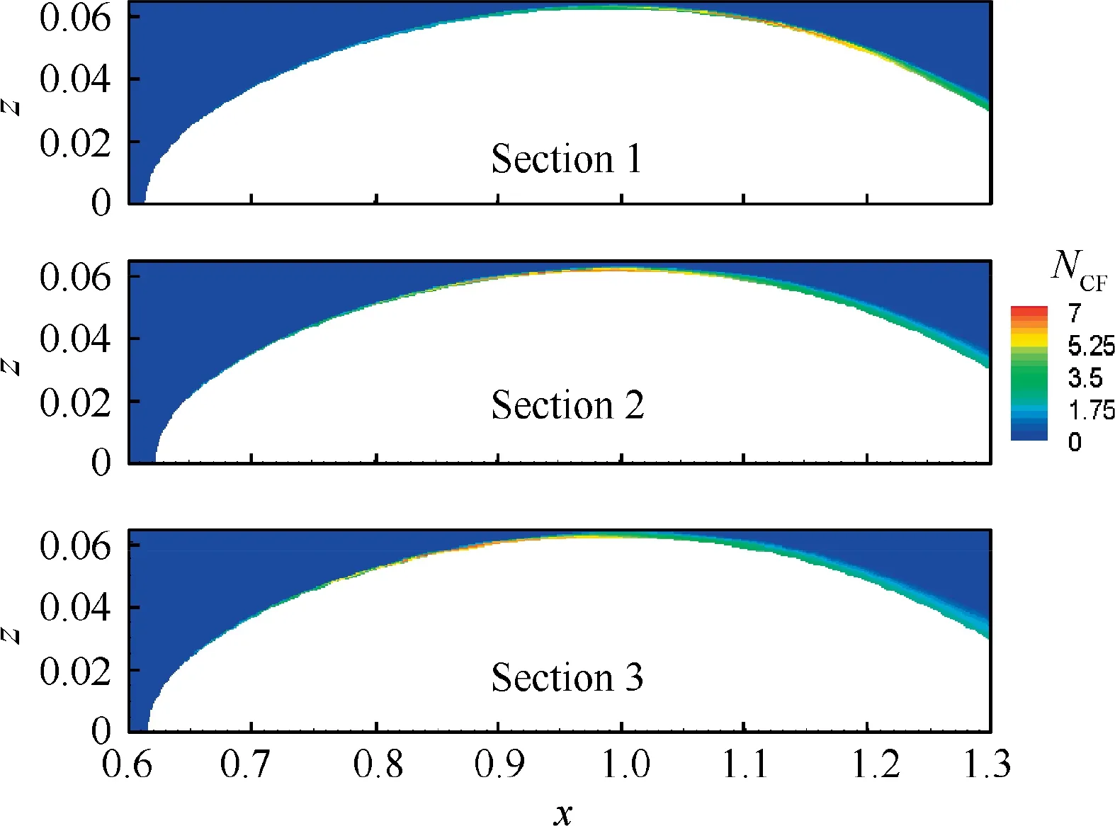
Fig. 5 Distribution of NCF factor at various spanwise sections on upper surface.
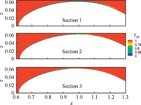
Fig. 6 Distribution of effective intermittency factor at various spanwise sections on upper surface.
3.3. 6:1 inclined prolate spheroid
The third case for validation is the 6:1 inclined prolate spheroid,45,46which exhibits complex flow phenomenon on the curved surfaces. It is very difficult to conduct standard LST analysis on the inclined prolate spheroid using traditional eNmethod.As stated in Ref.46,the boundary layer equations along the streamlines should be solved after the inviscid flowfield is obtained. Then, the two N factor (NTSand NCF) eNapproach is employed for linear stability analysis. This standard analysis is not easy to implement. Therefore, it is necessary to establish the transport equation for T-S waves and crossflow waves, which can replace the standard LST analysis method approximately.
The experiment was conducted in the DLR 3 m×3 m lowspeed wind tunnel by Kreplin et al. and the experimental data can be found in related researchers’ papers.47,48The length L of the spheroid is 2.4 m. The freestream turbulence level is low and Mach number is 0.136. The number of near-wall grid elements in the wall-normal direction is 201 so that y+(1) of the cell next to the wall is smaller than 1.0. According to the standard LST analysis,4610.0 and 6.0 are set as critical value of NTSand NCFfactor for every case in this section, respectively. Fig. 7(a) and Fig. 7(b) display the predictions at Reynolds number of 6.5×10⁶compared with the experimental data at α=15° and α=20°, respectively. From the skin friction contour, a large proportion of transition positions are in good agreement with the experimental data and the predicted position dominated by crossflow is slightly behind the measured data, which can be acceptable.

Fig. 7 Comparison of skin friction coefficient contours between present predicted results and experimental data9 on 6:1 prolate spheroid.

Fig. 8 Comparison of skin friction coefficient contours between present predicted results and experimental data on 6:1 prolate spheroid at angle of attack of 29.5° with different Reynolds numbers.
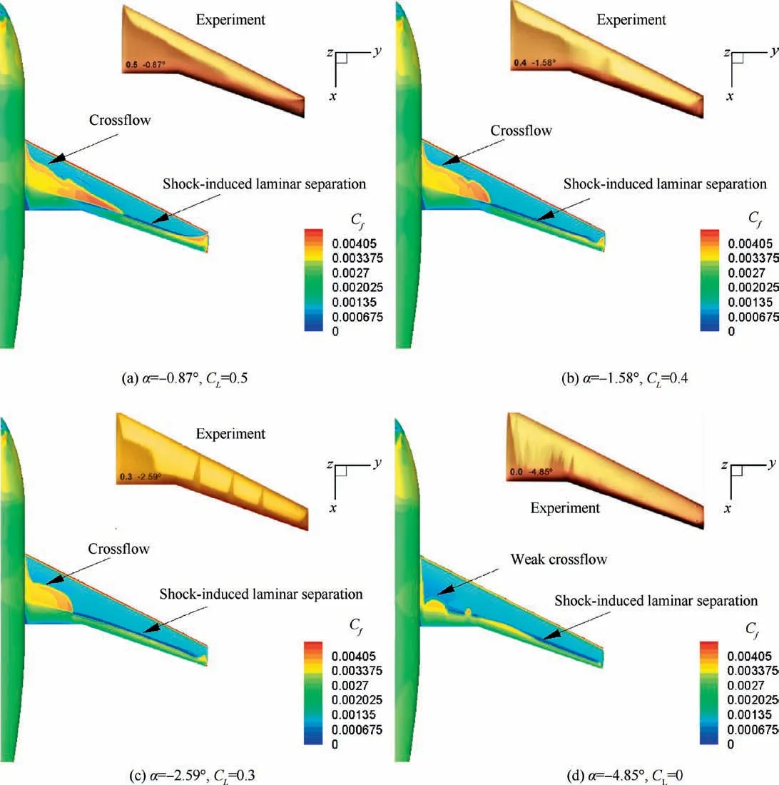
Fig. 9 Skin friction coefficient contour on upper surface of DLR-F4 wing compared with experimental data.
With a further validation,as shown in Fig.8(a)and(b),in the case of Re=4.48×10⁶, crossflow instability triggers the transition in the middle of the prolate spheroid, Φ is the angle in the cross-stream direction measured from windward side of prolate spheroid. Subsequently, the crossflow instability becomes stronger as Reynolds number increases to Re=8.52×10⁶. It should be acknowledged that most parts on the prolate spheroid are in good agreement with the standard LST analysis results as well as the measured transition locations, especially in the strong crossflow instability dominated region (nearly from x/L=0.2 to x/L=0.8). There are some deviations near the head region where the T-S instability is strong.The reason for the deviations between the present results and standard LST analysis results near the leading edge is probably the precision loss from the localization of the non-local variables used in the present transport equation.Therefore, for this inclined prolate spheroid with large angle of attack, the flow phenomenon around it is so complicated that these prediction deviations of the area near the head are acceptable and understandable.
3.4. DLR-F4 wing-body configuration
The transonic DLR-F4 wing-body configuration, measured in the European Transonic Wind tunnel (ETW) through Temperature-Sensitive Paint (TSP) technique,5,49is selected for validation in transonic flows. The experimental data indicates that stationary crossflow dominates transition on the inboard wing and T-S instability or shock-induced laminar separation appears on the outboard wing. The Mach number is 0.785 and the Reynolds number based on the mean aerodynamic chord is 6.0×10⁶. The freestream turbulence intensity is less than 0.05%,so it can be seen as a low-disturbance environment.Song et al.29conducted standard LST analysis on the DLR-F4 wing, which confirms the experimental phenomenon that crossflow instability dominates the inboard region and TS instability or shock-induced laminar separation leads to transition on the outboard region. Moreover, compared with the measured transition position, it points out that the critical value of NTSand NCFcan be set as 10.5 and 7.5, respectively.The number of near-wall grid elements in the wall-normal direction is 401 so that the average value of y+(1) of the cell next to the wall equals 0.95.
Fig.9 illustrates the skin friction on the upper surface of DLRF4 wing-body compared with the measured TSP results at α=-0.87° (CL=0.5), α=-1.58°(CL=0.4), α=-2.59°(CL=0.3)and α=-4.85°(CL=0),respectively.At the former three angles of attack, the crossflow instability on the inboard wing are captured well compared with the experimental data.When the angle of attack is -4.85°, only weak crossflow is predicted,which seems to be in accord with the measured TSP data.Overall,the crossflow instability and the shock-induced transition are both captured well using the present improved transport equation.Both the crossflow instability dominated area and the shockinduced transition area can be accurately identified.Consequently,the improved transport equation for NCFfactor in this paper can be considered as a reasonable and valid transition prediction model for stationary crossflow instability in subsonic and transonic boundary layers.
4. Conclusions
In this paper, an improved local transport equation for stationary crossflow instability has been developed and validated through extensive classical flow cases. The performance of the present equation is encouraging, reasonable and potential. As a whole, after the improvement and expansion of this paper,the model has become more mature. The predicted results by the present transport equation can be applied to replace the standard LST analysis method approximately for stationary crossflow instability in subsonic and transonic boundary layers. In conclusion, this improved model is more robust and more concise, and can be applied widely.
(1) The new helicity Reynolds number ReH,newand the new crossflow strength factor Hcrossflow,newproposed in this paper make the transport equation greatly simplified.Meanwhile, even though the functions of the crossflow characteristic thickness and curvature correction are removed, the prediction accuracy of the improved version is still high.(2) The compressibility effect is taken into account in the present transport equation so that this model can be applied to transonic flows reasonably from the perspective of theoretical research, which shows good application scope. The compressibility correction is more important for supersonic/hypersonic flows. The present model will be extended to high-speed flows in the future work.(3) The next step is to establish the database for the critical value of NCFfactor. This open issue is very important for transition prediction using the eNmethod.
Acknowledgement
This work was supported by the National Science Foundation for Young Scholars of China (No.:11802245).
杂志排行

CHINESE JOURNAL OF AERONAUTICS的其它文章
- Design and experimental study of a new flapping wing rotor micro aerial vehicle
- CFD/CSD-based flutter prediction method for experimental models in a transonic wind tunnel with porous wall
- Prediction of pilot workload in helicopter landing after one engine failure
- Study of riblet drag reduction for an infinite span wing with different sweep angles
- Modulation of driving signals in flow control over an airfoil with synthetic jet
- Strong interactions of incident shock wave with boundary layer along compression corner