A brief review of alternative propellants and requirements for pulsed plasma thrusters in micropropulsion applications
2020-02-24WilliamYeongLiangLINGSongZHANGHaoFUMengchengHUANGJustinQUANSAHXiangyangLIUNingfeiWANG
William Yeong Liang LING, Song ZHANG, Hao FU, Mengcheng HUANG,Justin QUANSAH, Xiangyang LIU, Ningfei WANG
School of Aerospace Engineering, Beijing Institute of Technology, Beijing 100081, China
KEYWORDS CubeSat;Electric propulsion;Micropropulsion;Plasma physics;Propellant;Pulsed plasma thruster
Abstract Technological miniaturization has enabled the development of small satellites weighing as little as 1 kg.Unfortunately,there is still a lack of suitable efficient micropropulsion systems at these scales.The pulsed plasma thruster is a structurally simple form of electric propulsion.This simplicity also makes it ideally suited for miniaturization.Its history can be traced back to applications in satellites that are much larger than micro/nano-satellites. The vast majority of modern pulsed plasma thrusters use solid polytetrafluoroethylene (PTFE) as a propellant. Unfortunately, at lower discharge energy levels such as those necessitated by the power limitations of micro/nano-satellites,PTFE has a tendency to exhibit carbon deposition, which can ultimately lead to thruster failure.In this new era of small satellites,it is important to consider alternative propellants in the miniaturization of pulsed plasma thrusters.This brief review discusses the needs and limitations of small satellites and alternative propellants that may be able to meet these needs.Such propellants may be able to offer advantages such as a longer thruster lifetime,a higher specific impulse,or a higher thrust-topower ratio. This would enable the development of different types of pulsed plasma thrusters that can be tailored towards specific mission requirements.
1. Introduction
The miniaturization of technology has enabled the development of devices such as smartphones that are much smaller than their predecessors but with significantly more computing capabilities. In recent years, this advantage has also been extended to satellite systems.While conventional satellites such as weather satellites and those that make up the Global Positioning System (GPS) can weigh several thousand kilograms,the miniaturization of technology has enabled the development of small satellites that can weigh as little as 1 kg. Of these, the CubeSat architecture is a common miniaturized satellite architecture where 1 unit (1U) corresponds to dimensions of 10 cm×10 cm×10 cm.1The typical weight of a 1U CubeSat is around 1 to 2 kg, and multiple units can be combined together to form progressively larger systems such as 2U,3U, 6U, etc.
It has been estimated in the SpaceWorks 2019 Nano/Microsatellite Market Forecast that around 2000 to 2800 micro/nano-satellites (1 to 50 kg) will require launch over the next 5 years.There has also been a significant increase in commercial adoption, with the most popular weight range being 4 to 6 kg. Such satellites have been used in applications such as downstream data analytics and communications.They are also being used in satellite constellations, with many satellites acting together to deliver a service.
Currently,most of these satellites are delivered to orbit with no propulsion systems.Within the Earth’s orbit,micropropulsion systems can be used to enable spacecraft to maneuver,extend their orbital lifetimes, perform orbital changes, and deorbit at the end of their lifetimes.However,while it has been possible to miniaturize electronic systems to create these small satellites, it has proven to be much more challenging to develop suitable efficient micropropulsion systems. Typical electric thrusters such as Hall and ion thrusters2,3that are used for larger satellites exhibit extremely low efficiencies when scaled down in size.4They also require cathodes and neutralizers for their operation, adding to the system complexity and total power requirements.
Table 15-13includes some examples of the smallest Hall and ion thrusters at the time of writing. The Exotrail miniature Hall thruster experiences a significant drop in performance below a power level of approximately 40 to 45 W.5The ThrustMe miniature gridded ion thruster using iodine propellant also has a minimum tested power level of around 35 W.6While the specific impulses of Hall and ion thrusters at power levels approaching and even exceeding the kW level can easily reach several thousand seconds, miniaturization results in a significant drop in both the specific impulse and the thrust efficiency.State-of-the-art Hall thrusters can achieve a thrust efficiency as high as 75%, but this drops to 15% or less (~3% at 37 W in Table 1)when miniaturized. One source of this inefficiency comes from wall losses that become significant as a thruster’s physical size is decreased, resulting in an increased surface area-to-volume ratio. It is also extremely challenging to push these conventionally high-power thrusters to lower power levels; the cathodes alone that are generally necessary for Hall and ion thrusters usually have heater power requirements in the order of 10 W.Having said that,there is also significant ongoing work on the development of heaterless cathodes with reduced power requirements.14Cathode-less thrusters such as the Radio Frequency (RF) thrusters and the microwave electrothermal thruster listed in Table 1 also exist,7-9but exhibit similar performance levels, with a thrust efficiency of ~2.5 at a power level of around 15 W for REGULUS7and ~0.3% at 35 W for Phase Four’s RF thruster.8In summary, at the time of writing, there appears to be significant limitations in the miniaturization of conventional higher-power electric propulsion systems to operation at sub-50 W power levels.As will be discussed in Section 3,this is the range of the typical power budget of smaller CubeSats.

Table 1 A summary of several cutting-edge low-power (sub-100 W) electric propulsion systems at the time of writing.
Without a propulsion system, satellites will be placed in orbit with no active means of control. On the other hand, a suitable propulsion system can open up significant new possibilities for micro/nano-satellites.15It would be possible to perform the large velocity change (Δv) maneuvers required to reach more distant targets beyond Earth orbit such as the Moon.16It would also enable the exploration of space using swarms of small satellites.17Furthermore, the staging of electric propulsion systems has also been suggested as a way to enable the development of interplanetary CubeSats.18
One promising micropropulsion system for these small satellites is the Pulsed Plasma Thruster (PPT).19,20PPTs are a simple form of space propulsion that have been studied since the dawn of the space age and have also seen actual use in space. As an electric propulsion system, they also have much higher propellant efficiencies(in terms of specific impulse)than those of chemical propulsion systems.19They were the first form of electric propulsion to fly in space (on the Zond-2)and have significant flight heritage due to their structural simplicity.21At input power levels approaching 100 W and higher(relatively high for PPTs), their specific impulses are typically several thousand seconds,and when optimized,thrust efficiencies can reach 30% (see ADD SIMP-LEX10in Table 1). The pulsed operation mode results in instantaneous power levels in the order of MW. Their structural simplicity also makes them ideally suited for miniaturization. When miniaturized to an input power level in the order of W, a typical specific impulse is in the range of several hundred to 1000 s with a thrust efficiency of approximately 10%. This is similar to the performance of the leading miniaturized Hall and ion thrusters at the time of writing, with the exception that PPTs are much easier to miniaturize and can even be operated at input power levels as low as several watts (see Busek MPACS11,12and BmP-22013in Table 1). Therefore, they are a very promising option for sub-50 W thrusters. Above this power level, other systems such as Hall and ion thrusters begin to exhibit their advantages better. More recently, several PPTs have been developed around the world specifically for use in CubeSats.22-24Companies such as Busek Company,Inc.,Clyde Space Ltd.,and Mars Space Ltd.11-13,25,26have also developed PPT Cube-Sat modules. However, all of these thrusters still use typical solid fluoropolymer called polytetrafluoroethylene (PTFE) as propellant. While the vast majority of PPTs in research and development currently use PTFE, gaseous, liquid, and solid propellants have all been studied in the past, and further research is still ongoing. This brief review will discuss the propulsion needs in micropropulsion applications such as on CubeSats. It will also cover a brief history of PPT propellant types that are suitable for micropropulsion applications and give a summary of research trends and results. The use of different propellants can enable further optimization of more performance parameters, such as an increased thrust-to-power ratio, or even an increased thrust efficiency.
2. Pulsed plasma thruster
2.1. History
The earliest known PPT was developed in Russia(formerly the Union of Soviet Socialist Republics (USSR)) and used gas pressure to discharge capacitively stored energy with a converging-diverging nozzle.19Two different designs were developed in the USSR, one electromagnetic and one electrothermal. In the United States (US), PPT development was spearheaded by Guman and Palumbo at Fairchild Republic Company, and by Solbes, Thomassen, and Vondra at the Massachusetts Institute of Technology Lincoln Laboratory.19
As mentioned previously, the first PPT spaceflight was on the Soviet Zond-2, where it was used as the actuators of the altitude control system.21While the mission itself was intended to perform a flyby of Mars,communication was eventually lost with the spacecraft. Nevertheless, the PPTs were successfully tested and operated in space before the loss of the spacecraft.In the US,the first PPT flight was achieved on the LES-6 satellite, where solid PTFE propellant was used instead of gas.19,27This was because the initially conceived gas-fed PPT design failed due to the mechanical metering valve.
Most modern PPT systems today have many things in common with the thrusters used on the Zond-2 and LES-6 spacecraft. However, due to the need for further miniaturization and to improve the thruster efficiency,research into other propellants is currently still ongoing.
2.2. Operation
A typical PPT is very simple structurally,and typically consists of electrodes(a cathode and an anode),a main energy storage capacitor,propellant,and a spark plug to initiate the main discharge process.A schematic of a typical PPT with parallel electrodes is shown in Fig.1.A circuit diagram for the spark plug is omitted for simplicity.
Energy is first stored within the main capacitor, with the charging time being dependent on the power processing circuit and the pulse cycle of the thruster. The charging time is typically in the order of 1 s, with the pulse cycle correspondingly being in the order of 1 Hz. In contrast, the discharge time of the capacitor is measured in the order of μs, meaning that the instantaneous power (~MW) delivered by the thruster is much higher than the average power consumption level(~W).
The discharge is initiated by the ignition of a spark plug.This spark plug can be either a low-energy high-voltage spark gap discharge or a semiconductor spark plug that decreases the required spark voltage.The energy delivered by the spark plug is negligible when compared to the energy stored within the main capacitor. This spark completes the circuit between the electrodes, which then begins the main discharge process through the discharge of the main capacitor. A discharge arc forms between the electrodes that ablates and ionizes the propellant, producing plasma. A kinetic model for material ablation in an ablative controlled discharge has been proposed by Keidar et al., with a triple-layer structure near the surface of the propellant.28This includes a Knudsen layer, which is a non-equilibrium layer, a hydrodynamic non-equilibrium layer dominated by collisions,and the plasma bulk,where ions,electrons, and neutrals are assumed to reach thermal equilibrium.The plasma will be comprised of elemental ions and molecules originating from the breakdown of the propellant.However,if the propellant is chemically reactive, e.g., a chemical propellant that releases energy exothermically, there will also be a release of heat energy related to the thermodynamic properties of the propellant.
The combination of the current passing through the discharge arc and plasma along with the electrostatic force between the electrodes results in a self-induced magnetic field and Lorentz force acting in the downstream direction. The Lorentz force accelerates both electrons and ions in the downstream direction,producing thrust.The neutral components of the discharge arc remain near the surface and expand at the gas expansion velocity, giving it the characteristic shape of an arc in discharge images.Fig.2 shows a time-integrated image of a single PPT discharge showing broadband light emission. The plasma plume is accelerated from the left to the right. Slight canting of the plume towards the cathode is visible,and is typical of PPTs.
There are generally two types of configurations for pulsed plasma thrusters, coaxial and parallel-plate electrodes.12,19The thrust produced from a pulsed plasma thruster is a combination of both electromagnetic and electrothermal thrust.In general, the parallel-plate configuration will have a greater electromagnetic thrust contribution while the coaxial configuration will be dominated by electrothermal thrust.The coaxial configuration is able to better confine and expand heated neutral gas.As the discharge energy of a thruster decreases(i.e.,as the maximum energy of the capacitor decreases), the proportion of electrothermal thrust will increase. This suggests that coaxial configurations may be preferable for low-power lowenergy systems such as those in micropropulsion applications.Furthermore, if exothermic chemical propellants are used, a coaxial configuration can also assist in the expansion and acceleration of the additional thermal component to produce thrust.Further details regarding the characterization and optimization of PPTs can be found in a recent review.20
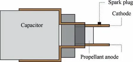
Fig. 1 Schematic of a typical PPT with parallel electrodes.
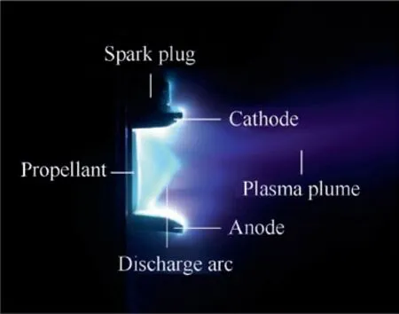
Fig.2 Time-integrated image of a single PPT discharge showing broadband light emission.
3. Micropropulsion requirements
Micropropulsion systems on microsatellites and nanosatellites can be used for spacecraft orientation as well as the main propulsion system. Thrusters that are used only for orientation or station-keeping can have a lower thrust and a lower total Δv capability.However,ifa thruster isto beused as the main propulsion system,this means that the thruster may be needed to perform significant orbital change maneuvers.This then requires a higher total Δv,which can be up to several 100 m/s for significant orbital changes.In order to escape the Earth’s orbit,a Δv capability in excess of 1 km/s is then required.Interplanetary transfers would require capabilities of several km/s. Compared with station-keeping,these applications will require a significantly larger amount of propellant mass,which will then increase the mass that has to be reserved for the propulsion system.
Small satellites such as CubeSats are severely limited in both mass and power. The typical mass of a 1U CubeSat unit is around 1 to 2 kg, and the typical power budget for a 1U CubeSat is 1 to 2.5 W. For 3U CubeSats, this power budget can increase to around 7 to 20 W.29,30However, this is still a very small power budget, severely limiting the propulsion options available. Temporary increases in the peak power can be achieved with onboard batteries,but this further strains the mass limitations of CubeSats.
If we consider the performance of a micropropulsion system,we must consider the balance between the specific impulse and the thrust or impulse bit of the system. Generally, an increase in thrust will decrease the time required to perform any orbital maneuvers, but will result in a decreased performance and a lower specific impulse. This then means that to deliver a given total thrust or Δv, more propellant will be needed due to higher propellant mass inefficiencies. Conversely, if the time required for an orbital maneuver can be lengthened, a micropropulsion system with a lower thrust and a higher specific impulse can then be used, reducing the total propellant mass required.
When considering the severe mass limitations experienced by nanosatellites, it may then be more beneficial to have a system with a higher specific impulse at the expense of thrust.With PPTs, this can be achieved by either optimizing the system towards a certain configuration,or by using alternative propellants, the latter of which will be discussed in this brief review. Different propellant types will produce different specific impulse vs.impulse bit behaviors,and an ideal propellant can then be selected based on specific mission requirements.
4. Pulsed plasma thruster propellants
4.1. Polytetrafluoroethylene (PTFE)
As mentioned in the introduction, the most common propellant in use today is solid PTFE. As such, it can be expected that there has been significant research done regarding it.PTFE is attractive due to its performance in PPTs,ease of storage, and the lack of a need for valves, injectors, heaters, etc.Even if we discount its specific impulse advantage when compared with chemical propulsion, its simplicity still makes it attractive for micropropulsion applications. Conversely, the primary drawbacks of PTFE are the need for a mechanical propellant feeding system (which may become significantly complex for higher propellant masses), carbon deposition on the propellant surface leading to thruster failure, and latetime ablation resulting in particulate emission and a decrease in the propellant utilization efficiency.
With the PPT on the LES-6 satellite,qualification testing of the thruster included accelerated life cycle testing at an operation rate of up to 4 Hz for the flight model prototype.27The number of pulses demonstrated was 107, which was the order of magnitude required by the satellite’s mission. The thruster was later used successfully for station-keeping tasks for over 16 months in space operation.
As mentioned before, one significant limitation with PTFE propellant is that it experiences carbon deposition over longduration operation. With the μ-Lab SAT II (50 kg) at the Tokyo Metropolitan Institute of Technology, tests showed that there was a sensitivity of the carbon deposition process with the pulse energy.31Operation below 3.6 J resulted in the PTFE propellant feeding system being susceptible to instability, causing non-uniform ablation of the propellant. Carbon deposition was found to affect sustained thruster operation at certain conditions.
At the University of Stuttgart in Germany, the ADD SIMP-LEX electromagnetic PPT was stress-tested with PTFE propellant.32The carbon in PTFE propellant has a tendency to build up in structured surface layers, which deposits on both the propellant surface and the electrodes. On the electrodes,it will reduce the effective electrode surface area available for discharge. With the ADD SIMP-LEX electromagnetic PPT at the University of Stuttgart, carbon contamination on the cathode was observed to be more severe than that on the anode, while the area closer to the PTFE propellant was kept cleaner by the discharge current. Furthermore, the mass bit was also found to increase with thruster operation, with the highest measured mass bit surpassing predictions by almost 50%. Sporadic misfires at a rate of 1 in 100 pulses were also observed. Unusual carbon deposition was observed, which was concluded to be due to insufficient PTFE propellant bar alignment, leading to thermal deformation at the propellant tip. This demonstrated a mechanical limitation to the use of solid propellants.
The tendency of PTFE propellant resulting in thruster failure due to carbon deposition was also demonstrated with testing on the coaxial MicroPPT at the Air Force Research Laboratory by Keidar et al.33Here, carbon deposition was observed to develop over time, especially during operation at lower discharge energies. This is especially crucial for applications in micro/nano-satellites where the available power is severely limited.The cause of carbon deposition was suspected to be carbon flux returned from the plasma rather than incomplete decomposition of the PTFE propellant. Particle simulations of the near-field plasma plume predicted that there was a substantial population of ions with a negative axial velocity,resulting in backflow contamination that flowed mainly onto the thruster. In particular, carbon ions have a higher negative velocity due to their higher mobility,resulting in their domination in the backflux on the thruster.It is believed that at higher discharge energies,there is a higher PTFE surface temperature and a higher ablation rate, resulting in the prevention of carbon build-up. However, as micro/nano-satellites are typically limited by available power, this suggests that carbon deposition with PTFE will become a more serious problem as PPTs are further scaled down in size.
It is important to note that the developmental history of PTFE as a PPT propellant has been largely based on applications in larger satellites with more available power.For example, the LES satellite series had a mass of around 150 to 200 kg, and the measured weight of the PPT system was around 7 kg.The discharge energy of the LES 8/9 flight thrusters was around 20 J, and the thrusters were fired at 0.5 to 1 Hz, suggesting an operating power requirement of 20 to 40 W. Another example would be the PPT on the 600 kg EO-1 satellite,which had a discharge energy around twice that of the LES PPT and weighed around 5 kg.34These values are around an order of magnitude higher than what is needed for micro/nano-satellites and CubeSats. Nevertheless, almost all modern PPTs for CubeSats still use PTFE as a propellant by default due to its research maturity. While the PPT has had a long history of research, we must remember that several design choices such as PTFE propellant were made in an era of larger satellites. Although PTFE performs well in such applications, in the current era of miniaturized satellites, it is important to reassess its viability and consider alternative propellants.
4.2. PTFE variations
Due to the research maturity of PTFE compared with other propellants, there have been several prior studies that examined PTFE propellant composited with other materials. This was done in attempts to improve its performance.
(1) Addition of LiOH and InBr to PTFE
During the early stages of PPT research in the US,Palumbo and Guman investigated PTFE seeded with 10% and 30%LiOH and InBr.35With LiOH, a monotonic decrease in the impulse bit was observed with both 10% and 30% samples.These propellants exhibited a negative relationship between the performance and the operation time. The peak current was observed to decrease as the number of discharges increased. This was concluded to be due to the deposition of a high-resistance compound on the electrodes, which then increased resistive losses and resulted in less energy entering the plasma. The original performance was recovered when the electrodes were cleaned and replaced,confirming the negative effect of electrode deposition. On the other hand, there was no noticeable abnormality with InBr but also no significant increase in the performance when compared with pure PTFE.
(2) Addition of carbon to PTFE
The impregnation of PTFE with 2%carbon by weight was tested as a propellant at the NASA Glenn Research Center.36Plasma parameters such as the electron temperatures and the electron number densities were similar to those of pure PTFE,but the ablation rate was approximately 50% that of pure PTFE. This decreased ablation rate was attributed to the fact that the additional carbon molecules in the propellant were able to partially absorb the discharge arc radiation, resulting in a potential reduction in the emission of particulates.Despite the decreased ablation rate, the thrust-to-power ratio was found to be only 3% lower than that of pure PTFE. Consequently, the specific impulse increased by almost 75% when compared with that of pure PTFE. Furthermore, the thrust efficiency was also doubled when compared with that of pure PTFE. However, one matter of concern with the addition of carbon is an increased likelihood of carbon deposition between the electrodes. This may be further exacerbated by operation at low discharge energy levels. Further investigations are required with miniaturized PPT systems to determine if this poses a significant limitation to the thruster lifetime.
(3) Multi-layered laminated propellant
The previously mentioned studies involved a microscale composite of PTFE with other materials. On the other hand,PTFE propellant laminated with other materials has also been tested,i.e.,layers of PTFE separated by layers of other propellant materials.37At the NASA Lewis Research Center, Leiweke et al.37investigated PTFE with High-Density Polyethylene (HDPE) in an attempt to increase the specific impulse of a PPT. This was pursued because PTFE is not an ideal polymer propellant due to its high molecular weight(which tends to decrease the specific impulse).HDPE was studied as a possible polymer to be used in conjunction with PTFE due to its high atomic fraction of hydrogen,with the potential to double the specific impulse of a thruster. Alternating layers of PTFE and HDPE were used to produce a propellant with a lower average molecular weight than that of pure PTFE.However,after less than 1500 discharges, the HDPE started to discolor, indicating that some charring of the propellant was beginning to occur.At the same time,the PTFE surfaces were free of discoloration. After only several thousand discharges,an increased carbon coverage was observed on the HDPE surfaces, after which intermittent problems were observed during thruster operation.In addition,recession of the propellant surface was found to be different between the PTFE and HDPE layers, with the PTFE layers found to have receded below the HDPE layers. Converse to the expected aim, the thrust with pure PTFE was found to be 26% higher than that of the PTFE/HDPE fuel,with similar values of exhaust velocities and specific impulses. Any future experiments that pursue multi-layered fuel must also address the variation in surface properties between different propellant types.
4.3. Non-volatile liquid perfluoropolyether
Several different types of liquid propellants have been studied in the long history of PPT research. Such liquid propellants can be divided into liquid metals (e.g., mercury, gallium,lithium, cesium, etc.) and other liquids (e.g., water, methanol,ethanol, etc.). Unfortunately, these generally require complex propellant systems that run contrary to micropropulsion requirements. However, more recently, an important term of distinction to note with non-metallic liquid propellants is their volatility. This refers to the tendency for a liquid to vaporize from a liquid to a gaseous state at a given background pressure.For example, at atmospheric pressure (1 atm=101,325 Pa),when comparing ethanol and glycerol, ethanol is considered to be a volatile liquid while glycerol is considered to be nonvolatile. This is because ethanol will readily evaporate while glycerol will remain stable in a liquid form up until a boiling point of 563 K (ethanol has a boiling point of 351 K but will slowly evaporate even at room temperature).A useful quantification of liquid volatility is its vapor pressure.This is the pressure produced by a vapor in thermal equilibrium with its solid or liquid state at a given temperature inside a closed system.It is related to the tendency of particles to escape from a liquid or solid, i.e., its evaporation rate. All liquids will boil when the background pressure is equal to their vapor pressures.
However, the previous discussion relates to atmospheric pressure, while PPTs are designed for operation in vacuum.The pressure levels in experimental vacuum chambers are typically in the order of 10-3to 10-5Pa. Furthermore, the background pressure in deep space is even lower, with the local environment around the Rosetta spacecraft having a pressure in the order of 10-9Pa during cruise and 10-8Pa during thruster operation.38In comparison,glycerol,which is considered to be non-volatile at room temperature, has a vapor pressure in the order of 10-2Pa at 25°C. This indicates that even liquids that are generally considered to be non-volatile will in fact be volatile when considered in the context of a PPT propellant.Such liquids will require pressurized vessels for propellant storage.
On the other hand, several promising liquid propellants have recently been examined with extremely low vapor pressures ranging from 10-4Pa to negligible values. In the context of operation in a vacuum,such liquids can truly be considered to be non-volatile as a liquid propellant. Liquid perfluoropolyethers (PFPEs) were first studied as part of the Liquid Micro Pulsed Plasma Thruster FP7 project in Europe.39Fig. 3 shows an image of liquid PFPE in a beaker in comparison with solid PTFE.40PFPEs are non-hazardous,have excellent chemical stability, are stable over a wide temperature range, and have almost negligible evaporation in vacuum at temperatures of up to 100 to 150°C.They are available in various grades, with some having a vapor pressure that is even lower than that of the environment around a spacecraft in deep space.Due to this,there is no need for pressurization,and propellant storage and delivery are dramatically simplified when compared with those of other liquid propellants.

Fig. 3 Liquid PFPE propellant in a beaker with a solid porous ceramic block, andsolid PTFE propellant.40 Reproduced from[Ling William Yeong Liang, Scho¨nherr Tony, Koizumi Hiroyuki.Characteristics of a non-volatile liquid propellant in liquid-fed ablative pulsed plasma thrusters.J Appl Phys 2017;121(7):073301],with the permission of AIP Publishing.
Two feeding approaches for non-metallic non-volatile liquid propellants have been explored experimentally. The first is a capillary feeding method driven by a syringe pump, and the second is a passive flow control method similar to that used with volatile liquid propellants.
(1) Capillary feeding method
The capillary system studied by Szelecka et al. used a micro-pump with a miniaturized step motor coupled to a lead screw driving a 2 mm-diameter piston.39This was envisioned to enable the precise control of the propellant volume injected for ablation.However,the ablation rate was found to be much lower than anticipated. It was also observed that the PPT could be operated as long as a thin layer of PFPE was present between the main electrodes,i.e.,rather than the PPT ablating the entire injected volume, the discharge appeared to occur over a flashover discharge path. Finally, the incorporation of additional mechanical elements increases the complexity of the system compared with those using solid propellants.
(2) Passive flow control method
To simplify the propellant delivery system, a passive flow control method using a porous ceramic has also been investigated.40,41This method further simplifies propellant delivery by removing the need for a syringe pump. The propellant is automatically replenished by capillary forces. These capillary forces dominate gravitational forces and would also be in effect in a microgravity environment. The non-volatile liquid propellant is impregnated within a porous ceramic substrate that is located between the main electrodes. The amount of propellant consumed in each discharge is automatically replenished as the liquid interfaces realign themselves to produce the surface area with minimum energy.
While the passive flow method is superficially similar to that used by Scharlemann and York for volatile liquid propellant,42there are significant operational and physical differences when applied to a non-volatile liquid propellant. With a volatile liquid, there is constant outgassing of the propellant through the porous medium.In fact,it is this outgassing that is ignited as propellant in the main discharge. However, with a non-volatile liquid, no such outgassing will be present due to the extremely low vapor pressure of the liquid propellant.This means that there will be no issue regarding constant venting and propellant loss. Instead, the propellant will be supplied as a thin layer of propellant that spreads across the exposed area between the electrodes. This is then ablated in a process identical to the ablation process in solid-fed ablative PPTs operating with PTFE propellant. However, it is important to note two major distinctions when compared with solid propellant: (A) liquid interfaces are mobile and will always restore themselves within the unablated porous medium, as opposed to a solid propellant that slightly changes in structure as its mass is ablated; (B) feeding the porous ceramic can be performed using passive capillary forces without a need for backpressure or pumps, as opposed to a solid propellant where complex feeding mechanisms may be required for large propellant masses.
An experimental thruster was operated at energy levels of 5 to 45 J,but repeatability was best at energy levels greater than 15 J. Time-integrated images of single discharges with solid PTFE and liquid PFPE respectively can be seen in Fig. 4.40The arrows indicate the propagation directions of the plasma plumes.Red-hot areas of deposited carbon were observed with solid PTFE propellant,while no such deposition was observed with liquid PFPE. The carbon deposition resistance of PFPE was studied over several thousand discharges, with liquid PFPE exhibiting no carbon deposition at all(see Fig.540).This confirms that one of the major failure mechanisms of PPTs is completely absent when using liquid PFPE as a propellant.
4.4. Ethylene tetrafluoroethylene
In addition to PTFE seeded with LiOH and InBr, Palumbo and Guman also examined other thermoplastics as possible alternatives to PTFE very early during the development of PPTs.35However, most of these were found to exhibit significant carbon formation during thruster operation,resulting in a noticeable decrease in the impulse bit as a function of the operation time. These tests were also performed with a significant discharge energy level of 450 J. For some thermoplastics, the exposed surface was completely black after approximately 1000 discharges. The most promising alternative was Ethylene Tetrafluoroethylene(ETFE),which was found to have a specific impulse around 60%higher than that of PTFE.The reason for this was possibly due to the replacement of two fluorine atoms by two hydrogen atoms when compared with PTFE.However, none of the tested alternatives produced a thrustto-power ratio that was comparable with that of PTFE. Nevertheless, depending on the specific mission requirements of micro/nano-satellites, a higher specific impulse may be preferable to a higher thrust-to-power ratio.As ETFE is a solid propellant similar to PTFE, it is simple to implement in existing PPT designs.However,it is likely to exhibit different discharge characteristics and plasma parameters, thus requiring further investigations in the future.
In 2007,Tahara et al.studied ETFE at a lower power level than that used by Palumbo and Guman, finding that the general trends also translated well to lower discharge energy levels(~15 J).43As with the earlier results, the specific impulse of ETFE was found to be significantly higher than that of PTFE(570 s vs. 320 s). The thrust efficiency was also much higher than that of PTFE (17.2% vs. 12.6%). As can be expected from the earlier results, the thrust-to-power ratio suffered a decrease in exchange for this increased performance. Further detailed modern experiments with ETFE are still required to be performed at lower discharge energy levels suitable for micropropulsion systems.
4.5. Solid chemical propellant
The use of solid chemical propellants in PPTs combines a chemical release of energy with electromagnetic and electrothermal accelerations. They are typically used with coaxial designs to supplement the dominating electrothermal acceleration with a chemical release of thermal energy.
(1) Hydroxyl-terminated polybutadiene

Fig.4 Side-view time-integrated discharge images of a PPT with solid PTFE and liquid PFPE at a discharge energy of 40 J.40 The arrows indicate the propagation directions of the plasma plumes.Red-hot areas of deposited carbon were observed with solid PTFE propellant,while no such deposition was observed with liquid PFPE. Reproduced from [Ling William Yeong Liang, Scho¨nherr Tony, Koizumi Hiroyuki. Characteristics of a non-volatile liquid propellant in liquid-fed ablative pulsed plasma thrusters. J Appl Phys 2017;121(7):073301], with the permission of AIP Publishing.
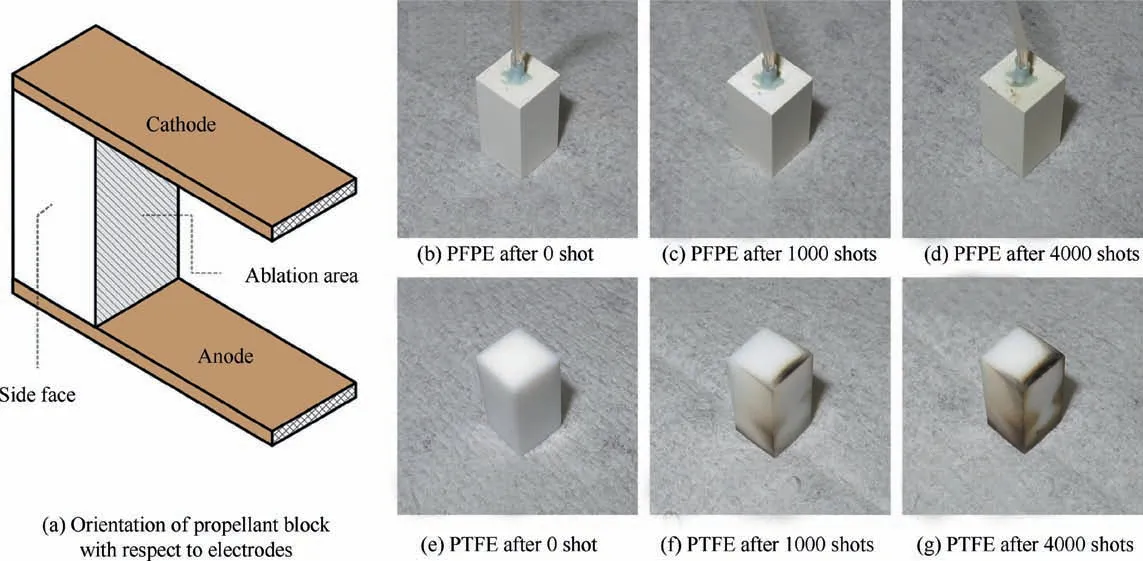
Fig. 5 Carbon deposition resistance of PFPE.40 Reproduced from [Ling William Yeong Liang, Scho¨nherr Tony, Koizumi Hiroyuki.Characteristics of a non-volatile liquid propellant in liquid-fed ablative pulsed plasma thrusters.J Appl Phys 2017;121(7):073301],with the permission of AIP Publishing.
At the Kyushu Institute of Technology in Japan, experiments were performed using a Hydroxyl-Terminated Polybutadiene-Ammonium Perchlorate (HTPB-AP)-based propellants. They are solid chemical propellants and were expected to increase the PPT thrust and thrust-to-power ratio with the help of the chemical energy within the propellants.Consequently,the impulse bits were found to be ~10%higher than that obtained using PTFE as a propellant, with correspondingly higher thrust-to-power ratios. Since the discharge waveforms did not change regardless of the propellant, the increase in the impulse bit was presumed to be due to an increased gas-dynamic contribution.44,45HTPB-AP propellants were also tested in a PPT with a coaxial configuration in order to better utilize the electrothermal component of the discharge energy.45The impulse bit was found to increase with an increasing proportion of AP in the HTPB-AP propellant,with the HTPB/AP=10/90 proportion (which is the closest to the propellant at the stoichiometric fuel-oxidizer mixture ratio) exhibiting the highest impulse bit measured. This impulse bit for 10/90 HTPB/AP was 20% higher than that using PTFE. However, for most cases (with the exception of 10/90 HTPB/AP), the mass shots for the chemical propellant were lower than that of the PTFE propellant, suggesting an increased thrust efficiency. When Al was added, the specific impulse of HTPB/AP/Al=20/80/20(20%by weight Al added to an HTPB/AP composition of 20%/80% by weight) was approximately 1.8 times higher than that of PTFE (1200 s vs.~670 s), and the thrust efficiency was approximately 2 times higher (~20% vs. ~10%).
Zhou et al. also conducted a series of experiments in 2017 using HTPB.46The mass bit was found to be approximately 50%that of PTFE.Regarding plasma parameters,the electron temperature was 0.18 eV lower than that of PTFE, while the electron density was almost double. The results showed that HTPB has a different energy distribution mechanism when compared with PTFE. Furthermore, the ablation process of HTPB is also different from that of PTFE, since HTPB also releases energy during ablation while PTFE absorbs energy.Conversely, HTPB consumes more energy in ionization than PTFE.
(2) Electric solid propellant
Electric Solid Propellants (ESPs) are an emerging area of research with potentially major implications in propulsion.The application of electric power to an ESP results in the solid propellant being ignited and exothermically decomposed.This continues until the power is removed. The continued development of ESPs for rocket propulsion applications resulted in the production of a formula that achieved a higher specific impulse and conductivity compared with earlier formulations. This is referred to as Higher Performance Electric Propellant(HIPEP). It is a Hydroxyl-Ammonium-Nitrate (HAN)-based energetic material. The plasma plume of a PPT using HIPEP as the propellant was recently studied.47,48The impulse bit was found to vary significantly from pulse to pulse and thruster to thruster. Variations of up to 40% over the thruster lifetime and 60% from thruster to thruster were observed, with the main suspected cause being inconsistencies in the propellant production process. The plume was found to be weakly ionized gas consisting of high-temperature electrons in lowrelative temperature ions and neutrals, indicating that the acceleration mechanism was dominated by electrothermal energy. Thermal inefficiency was identified relative to PTFE PPT plasma plumes, despite a stored energy of 40 J that was in the upper range of PPT operation.This suggested that most of the thermal energy from the discharge was deposited into the thruster components instead of the propellant and plasma.In summary, HIPEP behaves similar to PTFE, but with a higher mass bit,with the mass bit per ablation area being more than an order of magnitude above those of typical PPTs(~790 μg/cm2vs. 1 to 50 μg/cm2). However, the electron temperature, electron density, and ionization fraction are lower when compared to those of PTFE.
4.6. Sulfur
Another alternative to PTFE that has been investigated is sulfur. This was tested in a coaxial configuration with the target application being in CubeSats.49The thrust-to-power ratio was found to be several times higher than that of PTFE. This was attributed partially to the relatively low heat of vaporization and ionization energy of sulfur when compared with those of other propellants. The resulting larger ionization fraction would increase the propellant utilization efficiency, but the heavier sulfur ions have a lower plasma velocity, which then takes back some of the gains. The plasma velocity of sulfur was estimated to be between 68% and 81% of the PTFE plasma velocity at discharge energy levels of 10 to 65 J. At~20 J, the thrust efficiency was 25%. The use of sulfur as a propellant may be able to negate the carbon deposition lifetime issues present with PTFE propellant due to the lack of carbon in the propellant.
5. Discussion
The last several decades have seen the use of propellants in PPTs ranging across the entire physical spectrum of gases,solids, and liquids. While initial experiments were performed using gas-fed PPTs, these were eventually limited technologically by the lack of suitable fast-acting valves with reaction times suitable for extremely short PPT discharge times. The addition of required pressurization and a feeding system results in an increasingly complex system. In the context of micropropulsion, the requirement of these additional devices increases the challenges in miniaturization. Eventually, focus shifted to the use of solid propellants, of which PTFE was found to be the most promising due to its higher thrust-topower ratio. Since then, PTFE was and is still considered to be the ‘‘gold standard” propellant for PPTs, and almost all designs and flight models have used some form of PTFE as the propellant.
However, while PTFE better resists carbon deposition and charring compared to other solid propellants,it is still prone to the problem, especially at lower discharge energies at which micropropulsion systems must operate. This is one of the major limitations in the ultimate lifetime of a PPT.Larger propellant masses also require an increasingly complex feeding system due to the solid nature of the propellant. Due to these drawbacks, research was also conducted using liquid propellants.However,the issue of their stability in vacuum and leakage issues had not been resolved until the very recent introduction of non-volatile liquid propellants. These potentially have the capability to replace solid PTFE in certain PPT applications in the near future. In particular, the use of a non-volatile liquid propellant with passive flow control eliminates the need for pressurization and active feeding systems,making a system much less complicated and easier to miniaturize.
With respect to micropropulsion, the fundamental requirement for any system is simplicity and the ability to be miniaturized. When considering this, solid propellants are the most suitable due to their lack of a need for secondary propellant systems.Non-volatile liquid propellants with passive feeding systems also exhibit similar advantages. However, the use of gaseous or volatile liquid propellants will necessitate secondary systems such as pressurized tanks and feeding valves,increasing system complexity and the number of challenges associated with miniaturization.
The most suitable propellant for a micropropulsion PPT system will depend on the mission requirements. While nonvolatile liquid PFPE shows promise,compared with solid propellant designs, it is still early in the development phase, with further studies required to identify the ideal use-case scenarios and implementation process. With solid propellants, several alternatives to PTFE such as ETFE, chemical propellant,and sulfur are available. These have different advantages and disadvantages,and are also not as well studied as PTFE.A list of some of the propellants discussed here is shown in Table 235,36,39,43-45,47,49for easier comparison. However, it must be cautioned that (A) a comparison between thrusters is difficult due to different designs, base performance levels,and measurement methodologies; (B) many of these studies are at the early stages where researchers are trying to understand the behaviors of particular propellants. For example,the ESP thruster has a relatively low specific impulse of~200 s, but is only an initial unoptimized configuration intended to help guide the design of higher-performance variants. Furthermore, some other propellants have not yet had their performances fully characterized, with previous work instead studying their plasma discharge characteristics and other fundamental parameters. Note also that the thrust-topower ratio can vary considerably between thrusters. It is a function of the thruster geometry and capacitor properties.The best examples for comparison in Table 2 are those where PTFE was tested as a reference on the same experimental system. The shading in Table 2 identifies propellant pairs where different propellants were tested on the same system. The thrust-to-power ratio is represented in μN s/J due to the pulsed operation mode of PPTs.
ETFE exhibits a higher specific impulse but a lower thrustto-power ratio when compared with PTFE. As mentioned in the introduction,this trade-off may be advantageous in certain applications since mass is a premium on micro/nano-satellites.For missions with higher Δv requirements,the propellant mass fraction may become a significant part of the propulsion system. In these situations, a higher specific impulse may then become more desirable as it will reduce the amount of propellant required to deliver a given Δv. For applications such as spacecraft orientation or station-keeping, the propellant mass fraction will be significantly smaller, meaning that the specific impulse may not then be a primary concern. Note however that detailed experiments with ETFE are fairly dated and that some were also performed at significantly higher discharge energy levels(~450 J).As such,the specific impulse and thrust efficiency values listed for one particular experiment for this propellant pair were significantly higher than those for the others.35On the other hand, some experiments performed at lower energy levels demonstrated that the general trends were also carried to lower energy levels.43As mentioned previously,more modern experiments at micropropulsion energy levels are needed for further evaluation.
For situations that require a higher thrust-to-power ratio,sulfur propellant shows potential in comparison to PTFE.This may be attractive for cases where a spacecraft is required to perform specific maneuvers in a short amount of time. This is relevant in situations such as orbital transfer to a higher orbit, where a longer duration spent during the transfer process will reduce the usable lifetime of the satellite. Another advantage is that sulfur propellant will negate thruster failure due to carbon deposition between the electrodes, a significant issue with micropropulsion PPT systems operating at low discharge energy levels.
Chemical propellants such as HTPB and electric solid propellants are also attractive in that they combine the chemical release of thermal energy with a coaxial configuration to supplement electrothermal thrust. However, as with the alternatives to PTFE, they are also early in the development phaseand have exhibited significant variations between propellant samples and higher thermal inefficiencies compared with PTFE. Further studies are required to properly characterize their performances and ideal use-cases. As mentioned in Section 2,while other propellants only undergo an ablative breakdown that results in the formation of plasma from propellant components, chemical propellants will also release energy exothermically in addition to the ablative controlled discharge.Unfortunately,to the extent of our knowledge,there has yet to be a detailed study regarding the chemical reactions of particular propellant combinations in PPTs. For most propellants,the relevant physics relate to the ablative breakdown process mentioned earlier. However, if a wider range of propellant types is to be studied in the future, a better understanding of their behaviors through both physical and numerical studies will be required.
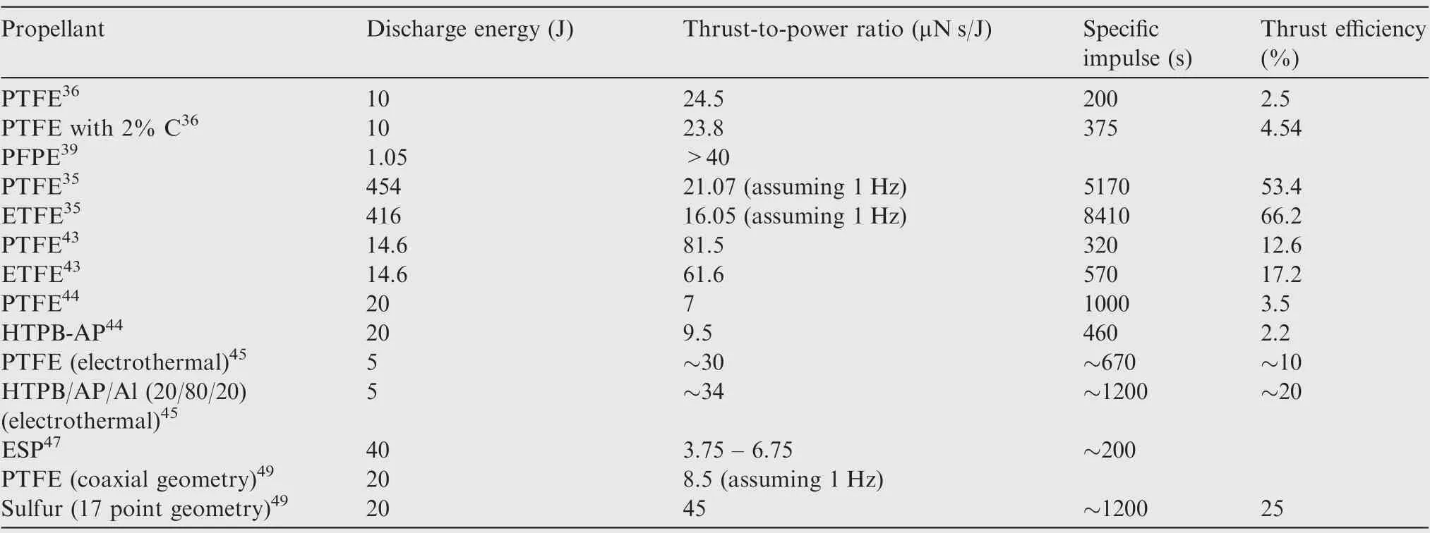
Table 2 Comparison of performances of various propellants.
As PTFE has been the‘‘gold standard”PPT propellant for several decades, it has been studied in much more detail than other alternatives. However, with the advent of micro/nanosatellites, it has become necessary to consider alternatives in the miniaturization of the PPT. As mentioned earlier, several alternative propellants have demonstrated promise in early experiments,but still require further characterization and optimization.It is also possible that a PPT designed for PTFE propellant will not operate efficiently with a direct propellant replacement.Instead,it is necessary to understand the ablation process and plasma parameters of these new propellants in order to best utilize them.
6. Conclusions
The miniaturization of electronics has enabled the development of micro/nano-satellites weighing as little as several kilograms, and the cost of development and access to space has decreased by several orders of magnitude. With the development of suitable micropropulsion systems, the capabilities of these micro/nano-satellites can be significantly extended,possibly even putting interplanetary missions within reach.The long history of PPT development and their inherent simplicity make them ideally suitable as micropropulsion systems. Current research in alternative propellants further opens the door to PPTs that can be tailor-designed for specific mission requirements.With such propellants available,it will then be possible to develop a wide range of micropropulsion systems based on PPTs to meet particular mission requirements, ranging from a high specific impulse to a high thrust-to-power ratio.
From this review, it is apparent that micro/nano-satellites have different propulsion requirements compared with conventional satellites. However, PPTs have been developed over several decades with the primary focus being implementation in larger satellites. With the advent of small satellites in the kilogram weight level, it has become necessary to revisit the adoption of PTFE as the propellant of choice in miniaturized PPT systems.
With conventional PTFE propellant, the most significant restriction towards miniaturization is carbon deposition at low discharge energy levels. This will result in the premature failure of the thruster due to short-circuiting of the electrodes.New alternatives such as non-volatile liquid PFPE and sulfur have demonstrated that they can operate without exhibiting carbon deposition, thus negating this failure mode during the miniaturization of thrusters.
When considering specific performance requirements for micropropulsion,alternatives such as ETFE and chemical propellants have also demonstrated different capabilities compared to PTFE. Chemical propellants are able to provide additional thermal energy from chemical reactions, supplementing the electrothermal thrust that can be obtained from coaxial PPTs. On the other hand, ETFE exhibits a higher specific impulse at the expense of a lower thrust-to-power ratio. This may be important in applications that require the propulsion system to provide a high total impulse and Δv. In such cases,the propellant mass may become a more significant fraction of the total thruster mass, and a higher specific impulse would then be beneficial in decreasing the required propellant mass.
Acknowledgements
This work was supported by the National Natural Science Foundation of China (No. 11802022) and the Beijing Institute of Technology Research Fund Program for Young Scholars.
杂志排行

CHINESE JOURNAL OF AERONAUTICS的其它文章
- Design and experimental study of a new flapping wing rotor micro aerial vehicle
- CFD/CSD-based flutter prediction method for experimental models in a transonic wind tunnel with porous wall
- Prediction of pilot workload in helicopter landing after one engine failure
- Study of riblet drag reduction for an infinite span wing with different sweep angles
- Modulation of driving signals in flow control over an airfoil with synthetic jet
- Strong interactions of incident shock wave with boundary layer along compression corner