Design and characteristics of a new type laminar plasma torch for materials processing
2020-01-10XiuquanCAO曹修全andLinCHEN陈林
Xiuquan CAO (曹修全) and Lin CHEN (陈林)
School of Mechanical Engineering, Sichuan University of Science and Engineering, Zigong 643000,People's Republic of China
Abstract Laminar plasma jet(LPJ)generated by laminar plasma torch(LPT)has a favorable temperature and velocity distribution. Thus, it is superior to the turbulent plasma jet in material processing.However, most of the reported LPTs usually operate at a relatively low output power with a relatively low arc voltage and thermal efficiency,which limits its capabilities.In this context,this paper attempts to design a new type of high-power LPT with a relatively low arc current and a high thermal efficiency. In the first section, the design principle of the main components is studied and discussed in detail,and a new high-power LPT is proposed.Then,the experimental characteristics of the proposed high-power LPT are examined. Experimental results reveal the following characteristics of the proposed LPT. (1) The max jet length of the proposed LPT reaches at 540 mm.(2)Its mean arc voltage is higher than 290 V when the LPT works with arc currents lower than 200 A,leading to an output power greater than 50 kW.(3)The mean thermal efficiency is higher than 50%. Lastly, the proposed LPT has been applied to spheroidize the aluminum oxide powers. The experiment results for the production of spherical powders show that the proposed LPT has a good characteristic for material processing.
Keywords: laminar plasma torch, design principles, high arc voltage with a low arc current,spheroidisation(Some figures may appear in colour only in the online journal)
1. Introduction
Due to the advantages such as low cost and requirements on the working environment, favorable jet characteristics [1],direct current (DC) plasma jet has been applied to waste treatment [2-4], plasma spraying [5-7], synthesis of nanoparticles [8, 9], etc. According to their flow status of the DC plasma jet, it is generally classified as turbulent plasma jet(TPJ) and laminar plasma jet (LPJ). Due to its favorable temperature and velocity distribution, LPJ is superior to TPJ in materials processing [10-12], e.g. synthesis of nanoparticles [13], plasma spraying [14], deposition of materials[15], production of hollow spherical powders [16] etc Thus,device for generating LPJ, termed as laminar plasma torch(LPT), has been invented and its experimental characteristics have been studied. For instance, Pan et al invented a LPT consisting of three main components: a rod cathode, copper inter-electrode and cylindrical anode with a diameter of 8 mm[12]. Its characteristics of different working parameters, e.g.working gas compositions, arc currents, gas flow rates, the diameter of the inter-electrodes, have been examined.Namely, it operates with a working power about 3-12 kW, a corresponding arc voltage only about 40 V and a mean thermal efficiency lower than 35% [17-19]. Osaki et al designed a high thermal efficiency LPT consisting of a rode cathode,four inter-electrodes and an anode with a diameter of 6 mm[20]. Its output power was about 2.35-3.43 kW with an arc voltage about 45 V. The maximum thermal efficiency is only 36.8%. Cao et al proposed a segmented LPT with a compression arc chamber,an anode diameter of 5 mm and a mean thermal efficiency of less than 40%[10].It works with a mean arc voltage merely about 100 V and a corresponding working power less than 12 kW.
Hence, most of the reported LPTs usually operate at relatively low output power with relatively low arc voltage and thermal efficiency, limiting its capability in materials processing.By increasing the arc current,the output power of the LPTs can be increased. Nevertheless, large arc currents tend to accelerate the erosion of the electrodes, thereby shortening the life of the electrodes.
In this case, Solonenko et al invented a high power cascaded LPT having an anode diameter of 18 mm [21]. By increasing the number of inter-electrodes, the output power was increased to more than 50 kW with an arc voltage about 300 V. However, when the distance between the pilot electrode and the anode is greater than 100 mm, it is difficult for the pilot arc to transfer from the pilot electrode to the anode smoothly [22].
This paper aims to discuss the design principle of a new type LPT for materials processing with high output power and relatively low arc current, accompanied with high thermal efficiency.In this paper,the design principles of the proposed LPT are introduced and its experimental characteristics are discussed and comprehensively verified.
2. Design principles of the LPT
According to the relationship between the working power P and the arc voltage U and the arc current I,a LPT can obtain higher working power by increasing the arc voltage U or arc current I. However, as the arc current I increases, the current density of the arc attachment increases, leading to an acceleration of the erosion of the electrodes.On the other hand,the arc voltage U can be increased by increasing the length of arc channel, which has a little effect on the arc density. In addition, the structure of the electrodes and the gas injection angles etc could also affect the erosion of the electrodes and the status of the plasma jet. Thus, the following principles could be considered to design a new LPT.
2.1. Design principles to obtain high working power with relatively low arc current and high thermal efficiency of a LPT
According to previous studies on the influence of the LPT's structures on their characteristics[23],LPT with a segmented anode (referred to as segmented LPT) displays more advantages, e.g. higher arc voltage and better jet stability than conventional plasma torch. The segmented LPT mainly consists of a cathode, a pilot electrode, an anode, some interelectrodes, and insulator rings. The anode and the interelectrodes are called segmented anode. A higher arc voltage of a segmented LPT can be obtained by increasing the number of the inter-electrodes to lengthen the plasma arc. In the case of a higher arc voltage, the segmented LPT can obtain a higher working power under the same arc current,and has little influence on the erosion of the electrodes. In addition, the inter-electrodes only withstand the radiant heat of the plasma arc, which reduces the heat loss. Thereby improving the thermal efficiency of the LPT. Hence, the proposed LPT in this paper adopts a segmented anode structure to obtain high power at a relatively low arc current.In addition, considering the advantages of the expansion arc chamber, e.g. higher thermal efficiency, better temperature,and velocity distribution, an expansion arc channel with an angle of 15° is applied to the proposed LPT.
2.2. Design principles of the cathode and the gas injection angle
As shown in figure 1, there are two different typical cathode structures: the rod-shaped cathode and the button-shaped cathode,which are constituted by inserting a tungsten rod(2)into a copper cover (1). Because of high-temperature resistance of the tungsten (Thoriated tungsten), the tungsten rod is always used to withstand the cathode attachment. According to the previous experimental results, the suitable diameter of the tungsten rod Dc(mm) is 5 mm.
Based on Steenbeck voltage principle, by providing a minimum power, the cathode arc attachment is always attached to the tungsten rod surface when LPT works with a rod-shaped cathode. Without the connection of the cathode attachment, the service life of the copper cover could be extended. However, due to its length and low thermal conductivity, it is hard to take away the heat of the tungsten rod in time by cooling the copper component.Compared with the rod-shaped cathode, the copper cover of the tungsten rod helps the tungsten rod of the button-shaped cathode to cool better by indirectly cooling the copper cover. Thanks to the better cooling effect, the button-shaped cathode could have a longer service life.In addition,button-shaped cathode usually uses tangential gas injection to compress the cathode arc attachment on the tungsten rod to prolong its service life.Based on the previous study [24], the working gas injected into the arc chamber with an angle of 30° could get a longer jet length, which is helpful for LPJ generation. According to our previous experimental study,when the gas injection angle is lower than 30°, the effect of increasing electric energy could be dominant over the effect of the decreasing velocity along the axial direction while the gas injection angle is larger than 30°, the effect of increasing energy and decreasing velocity along the axial direction is conversed. Thus, there could get a longer jet length when the gas injection angle is 30°.Therefore,the button-shaped cathode was adopted in the proposed LPT with a gas injection angle of 30°. After determining the gas injection angle, most of the gas was injected in the arc chamber in the axial direction of the LPT,while a small portion of the gas swirled.
2.3. Design principles of the inter-electrodes
The segmented anode structure could improve the arc voltage and avoid the large-scale shunting phenomenon of a LPT[25]. However, an improper design length of the inter-electrodes could result in a double arc phenomenon, causing an significant fluctuations of the plasma jet and rapid erosion of the inter-electrodes.
To avoid the double arc phenomenon, the length of the inter-electrode l should meet the following relationship [26]:
where E, Va, and Vcrefer to the corresponding electric field intensity,the anode voltage drop and the cathode voltage drop respectively. Thus, combined with experimental study, the inter-electrodes were designed properly.
The number of the inter-electrodes n is determined by the anticipated arc voltage U with the following relationship:
where E is the mean electric field intensity of the plasma arc.According to our experimental results [27], E is about 2 V mm−1when using pure nitrogen as the working gas and a low working gas flow rate for the generation of LPJ. l is the axial length of the inter-electrode. In the proposed LPT, with an anticipated mean arc voltage about 300 V, the number of the inter-electrodes is 11. The inter-electrodes are electrically isolated from each other by insulator rings (Material: Polytetrafluoroethylene)and cooled well in parallel by the cooling water at a set temperature. In addition,the axial length of the insulator rings is 2.1 mm.
2.4. Design principles of the anode
According to previous studies, a large axial length of the anode could cause a large-scale shunting phenomenon [10].The large-scale shunting always results in a pulsation of the plasma jet, accelerating the consumables of the anode. To avoid large-scale shunting phenomenon, the axial length of the anode should be limited. Therefore, the segmented anode construction was adopted to ensure a proper axial length of an anode.
When LPT uses a segmented anode structure, there are usually three typical anode structures:a Laval shape anode,a convergent part of anode, and a cylindrical shaped anode, as shown in figure 2.Using the Laval shaped anode,the velocity of the plasma jet could reach a supersonic level when the gas flow rate arrives at a certain level,thus shortening the time of the material particles in the plasma jet. Due to the compression and expansion construction of the Laval shaped anode,the velocity direction of the plasma jet is not consistent with the axial direction of the LPT well. The convergent part of anode consists of a compressed section with a compression angle about 30°−60° and a cylindrical section. In this case,the plasma jet can be compressed, resulting in a vertical velocity component of the plasma jet with the axial direction.The vertical velocity component of the plasma jet always reduces the length of the plasma jet. The cylindrical shaped anode could combine the advantages of Laval shaped anode and convergent part of anode to appropriately reduce the vertical velocity component of the plasma jet.
According to section 2.1, the proposed LPT uses an expansion arc channel. After the expansion arc channel is adopted, there is a vertical velocity component of the plasma along the axial direction in the arc chamber. Then, considering the favorable characteristics of the cylindrical shaped anode,the cylindrical shaped anode was adopted to rectify the vertical velocity component with a diameter of 16 mm. In addition,some spiral grooves were manufactured on the outer surface of the anode to enlarge the cooling surface to enhance its cooling effect.
Based on the above design principles of the main components, a new high-power LPT is proposed, as shown in figure 3. It mainly consists of a button-shaped cathode (a),two pilot electrodes ((b): (b1) is the first pilot electrode and(b2) is the second pilot electrode), nine inter-electrodes (c)and a cylindrical shaped anode (d). The main design parameters are shown in table 1. The axial lengths of the interelectrodes were decided by the equation (3), and their diameters were decided by the expansion angle of the arc chamber. Hence, No.9 inter-electrode adopted a compress structure to compress the plasma arc to an appropriate size to meet the anode diameter. In addition, in light of the previous study [22], when the length between cathode and anode is greater than 100 mm, two pilot electrodes are necessary for the ignition of the plasma arc successfully. Firstly, the pilot arc is ignited between the button-shaped cathode (a) and the first pilot electrode (b1). Then, the anode attachment of the pilot arc is transferred from the first electrode (b1) to the second pilot electrode(b2)automatically under the control of the power source. Lastly, the anode attachment is transferred from the second pilot electrode(b2)to the anode(d)and then LPT starts to work.
3. Experimental setups
In order to study the characteristics of the proposed LTP at atmospheric pressure, experiments were conducted with the working parameters shown in table 2.The experimental setup consists of a gas supply subsystem (1), a power source subsystem (2), the proposed LPT (3), a cooling subsystem (4)and a measurement subsystem (5), as shown in figure 4. The gas supply subsystem supplies the working gas (Pure nitrogen) to the proposed LPT accurately by using a mass flow controller.The power source subsystem adopts the DC power supply based on the insulated gate bipolar transistor with a conversion efficiency >90% and current fluctuation <1% to provide DC power to the LPT with a specified arc current.An igniting module to ignite the pilot arc with high frequency and high voltage is integrated into the power source subsystem.The cooling subsystem supplies cooling water to the proposed LPT at a specified temperature. The measurement subsystem will be illustrated in detail in the following section.

Table 1.The main design parameters of the proposed LPT (unit: mm).
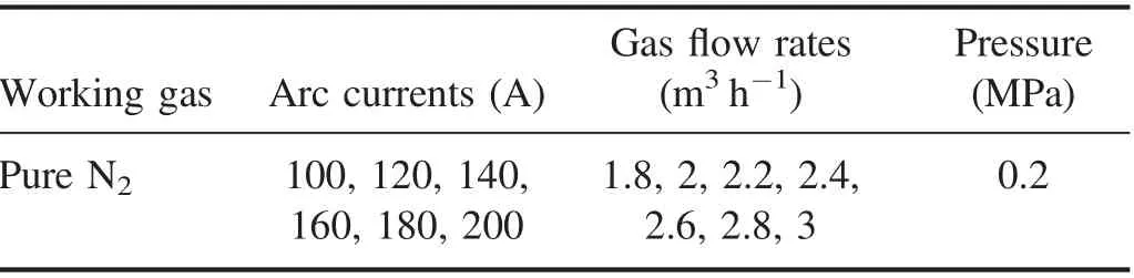
Table 2.Working parameters of the experiments.
The arc voltages of the LPT, working with specified parameters,were measured using a data acquisition module(NI USB-6210). The sampling frequency is 100 kHz. Using the measured voltages,the average arc voltages and the voltage variations of the proposed LPT were obtained by using a MATLAB program.
Two temperature sensors and a turbine flow meter were used to measure the input and output temperatures and the flow mass of the cooling water supplied to the proposed LPT respectively. The temperature sensors adopt thermocouple transducers. The temperature difference of the cooling water Δt can be obtained by using the output temperature minus the input temperature. According to the measured temperature differenceΔt and the flow mass m,the total heat energy taken away by the cooling water can be calculated by using the equation: cmΔt. Then, LPT's thermal efficiency and LPJ's mean specific enthalpy are calculated by using the equations (3) and (4) respectively:
whereη and P (kW) refer to LPT's thermal efficiency and working power at specified working parameters respectively,c(J kg−1°C−1),m(kg s−1),Δt(°C)the specific heat,the flow mass and the temperature difference of the cooling water respectively, ho(kJ g−1) LPJ's mean specific enthalpy,Ggas(g s−1) the working gas flow rate.
A CCD camera is used to automatically record the images of the LPJs generated by the proposed LPT with a sampling frequency of 0.5 Hz. The images were analyzed with a MATLAB program to obtain the average jet lengths with the corresponding working parameters.
4. Results and discussions
Through experiments, LPJ has been generated with the specified working parameters. Figure 5 shows one of the LPJ images generated by the proposed LPT with an arc current of 180 A and a gas flow rate of 2.2 m3h−1. The different jet characteristics of the proposed LPT are discussed in the following section.
4.1. Jet lengths
The jet lengths of the proposed LPT under different working conditions are shown in figure 6.As can be seen in the figure,the jet length increases first and then decreases to a certain level with the increase of the gas flow rate,and then increases as the arc current increases.To illustrate,firstly,when the gas flow rate is less than about 2.2 m3h−1(Excluding arc current = 100 A),the plasma jet is a laminar flow,and the jet length increases with the increase of the gas flow rate due to an increase in the effective working output power.Then,with the increase of the gas flow rate, the plasma jet gradually transforms from laminar flow to turbulent flow. Thus, the jet length decreases as the gas flow rate increases.Therefore,the jet length increases first and then decreases to a certain level with the increase of the gas flow rate.As arc current increases,the effective output power of the proposed LPT increases,resulting in the slight increase in jet length [10].
In addition, there are several outliers in figure 6, e.g. arc current ≥180 A,gas flow rate ≤2 m3h−1.At this point,the plasma jet appears a little green and an obvious fluctuation,possibly caused by a severe erosion of the electrodes.Besides,the error bars shown in the figure 6 were decided by the mean square error of the jet length under the specified working conditions.
4.2. Arc voltages and output powers
The arc voltages and output powers of the proposed LPT are shown in figures 7 and 8 respectively.As shown in figure 7,the arc voltage increases slightly with the increase of the gas flow rate, and decreases slightly with the increase of the arc current, which is consistent with the previous study [10].This trend could arise from the following relationship U = IR. When the gas flow rate increases at a fixed arc current,the arc will be compressed more intensely due to the increased aerodynamic force on the arc column, resulting in a decrease in the arc sectional area. In addition, with the increase of the gas flow rate, the density of the ionized particles would decrease. Thus, the decrease of the arc sectional area and the density of the ionized particles lead to a slight increase of the resistance R of the plasma arc,resulting in a slight increase of U. When the arc current increases at a fixed gas flow rate,the arc temperature,the arc sectional area and the density of the ionized particles all increase slightly. The slight increase of them results in the slight decrease of the resistance R of the plasma arc,thus the slight decrease of the arc voltage U. In addition, the error bars of the arc voltage shown in the figure 7 were decided by the mean square error of the arc voltage under the specified working conditions.
Figure 8 shows that the output power of the proposed LPT increases as the gas flow rate and the arc current increase. According to the calculation equation, the output power is the product of the arc voltage U and the corresponding arc current I. The arc voltage increases with the increase of the gas flow rate, resulting in the increase of the output power. When the arc current increases, its increase ratio is greater than the decrease ratio of the arc voltage,resulting in the increase of the output power. In addition,when the plasma jet is in laminar flow, the largest output power of the proposed LPT is greater than 50 kW with a mean arc voltage about 290 V. The mean arc voltage of the proposed LPT is much larger than that of the most reported LPT.
4.3. Thermal efficiency
The thermal efficiency of the proposed LPT under different working conditions is shown in figure 9.It is shown that the thermal efficiency increases from 47% to about 66% with the increase of the gas flow rate, and decreases slightly with the decrease of the arc current. As the gas flow rate increases,the plasma arc column is compressed more strictly because of the increased aerodynamic force generated by the radial pressure gradient, thus forming a thicker cold layer.The cold layer could reduce the radial heat transfer from the plasma arc to the arc chamber wall.The heat taken away by the cooling water decreases. Therefore, the thermal efficiency of the proposed LPT increases as the gas flow rate increases. As the arc current increases, the sectional area of the plasma arc increases slightly, resulting in a slightly thinner cold layer. With a thinner cold layer, the radial heat transfer becomes more serious, resulting in the increase of the heat transferred from the plasma arc to the arc chamber wall. Thus a slight decrease of the thermal efficiency appeared. Moreover, the mean thermal efficiency of the proposed LPT working with a laminar flow status reaches 50%, which is higher than that of most reported LPTs.
4.4. Specific enthalpy
The specific enthalpy of the LPT under different working conditions is shown in figure 10.The results show that the specific enthalpy decreases from about 39 to 22 kJ g−1as the increase of the gas flow rate, and increases with the increase of the arc current. From equation (4), specific enthalpy is proportional to the product of the arc voltage and thermal efficiency, and inversely proportional to gas flow rate.Although the arc voltage and thermal efficiency increase with the increase of the gas flow rate,the total increase ratio of them is slower than that of the gas flow rate,and thus the specific enthalpy decreases.Although the arc voltage and the thermal efficiency decrease as the arc current increases, the overall decrease ratio is slower than the increase ratio.Thus,the specific enthalpy increases.In addition,the mean specific enthalpy of the proposed LPT working with a laminar plasma flow reaches 33 kJ g−1.
5. Application for the production of spherical powders
In order to test the characteristics of the proposed LPT for material processing, the LPT was used to produce the spherical aluminum oxide powders.
5.1. Experimental setup for the production of spherical powders
As shown in figure 11, a special device for producing the spherical aluminum oxide powders was designed.This device consists of a heat exchange chamber and a cone collection chamber which were cooled by cooling water. A wooden shelf was used to support this device. The LPT was installed on the upper surface of the heat exchange chamber.
The raw aluminum oxide powers were injected into the LPJ with a specified feeding rate VPby using pure argon.Then, the powers were heated and spheroidized in the heat exchange chamber. Sequence, the spherical aluminum oxide powders were cooled and collected in the collection chamber.
5.2. Results and discussions
Using the optical microscope, the images of the raw aluminum oxide powders under 100 times and 200 times are shown in figure 12 respectively.From the images,it can be seen that the sizes of the raw aluminum oxide are 75-150 μm, and the raw powders are polygonal porous particles with irregular shape.
After the spheroidization by the LPJ with specified parameters, the images of the spherical aluminum oxide powders under 100 times are shown in figure 13. It is shown that the raw powders were spheroidized well. The spherioidization percentage is approximate 100%. The spherical aluminum oxide powders have smooth surfaces and good dispersion.The spheroidization has little influence on the size of the aluminum oxide powers.
The above experimental results show that the proposed LPT has a good characteristic for material processing.
6. Conclusions
This paper demonstrates the design principles and experimental characteristics of a new high-power LPT. From this study, the following conclusions can be drawn:
(a) The design principles of the main components of a new high power LPT working with relatively low arc current and high thermal efficiency are considered and discussed in detail to guide the design of the high power LPT.
(b) A corresponding experimental study presents the characteristics of the proposed LPT. The experimental results reveal that: (1) the longest jet length can reach 540 mm,(2)the maximum power is greater than 50 kW with a mean arc voltage about 290 V, (3) the mean thermal efficiency and specific enthalpy can arrive at 50% and 33 kJ g−1respectively.
(c) A corresponding experimental study shows that the proposed LPT has a good characteristic for material processing.
Although a new LPT with a power greater than 50 kW has been proposed, its design principles and experimental characteristics have been studied. Still, a larger power LPT should be designed and simulation studies on the underlying mechanism within and outside the LPT need to be carried out to optimize the design of LPT.
Acknowledgments
The authors appreciate the supports of the major project of Zigong Science and Technology Bureau (No. 2018YYJC13 and No. 2017DZ10), the Talents Introduction Project of Sichuan University of Science and Engineering (No.2017RCL37)and the Sichuan Provincial Key Lab of Process Equipment and Control's Project (No. GK201802).
猜你喜欢
杂志排行

Plasma Science and Technology的其它文章
- Experimental study of current loss of a single-hole post-hole convolute on the QG I generator
- Development of a data acquisition and control system for the International Thermonuclear Experimental Reactor neutron flux monitor
- Effect of the amount of trapped particulate matter on diesel particulate filter regeneration performance using nonthermal plasma assisted by exhaust waste heat
- The effect of atmospheric pressure glow discharge plasma treatment on the dyeing properties of silk fabric
- Spectral characteristic of laser-induced plasma in soil
- Weighted-averaging-based classification of laser-induced breakdown spectroscopy measurements using most informative spectral lines