Motions of the Floating VAWT Considering the Viscous Damping of the Spar Type Floating Foundation
2019-12-10LIULiqinZHAOHaixiangZHAOJingruiGUOYing
LIU Li-qin, ZHAO Hai-xiang , ZHAO Jing-rui , GUO Ying
(1. State Key Laboratory of Hydraulic Engineering Simulation and Safety, Tianjin University, Tianjin 300072, China;2. Technology Research Dept., CNOOC Research Institute Co., Ltd, Beijing 100028, China)
Abstract: The motion performance of a 5MW Φ-type Darrieus VAWT (vertical axis wind turbine)was studied in this paper. The floating foundation was of Spar type with heave plates, the viscous damping of which was calculated by using the CFD (Computational Fluid Dynamics) method. The surge, heave and pitch nonlinear coupling dynamic equations of the floating VAWT were established;three typical cases were used to assess the responses of the floating VAWT, and the effects of the aerodynamic loads on the motions of the floating VAWT were analyzed. The results show that the amplitudes of surge, heave and pitch of the floating VAWT are small for the three cases, while the mean values of surge and pitch for case 2 are relatively large due to the blades bearing large aerodynamic loads and the chord of the blades is large.
Key words: offshore wind power; truss Spar-type floating foundation; VAWT;dynamic response
0 Introduction
Based on the direction of the wind wheel rotation axis in space, the wind turbines are divided into horizontal axis and vertical axis wind turbines. Due to the relatively low cost, the horizontal axis wind turbine has developed rapidly in the last 30 years and occupied most of the wind power market share. With the increase of unit capacity (from 50 kW 30 years ago to the current 5 MW and planned 10-20 MW), the size of the wind turbine is becoming larger.The drivetrain of the horizontal axis wind turbine is placed at the top of the wind turbine. The placement of a large drivetrain at the top of the horizontal axis wind turbine will make it a less stable system, especially for the floating offshore wind turbines. Therefore, researchers recommended the vertical axis wind turbine again, such as the Deep Wind project in Denmark[1]and the Inflow project in France[2]. The drive system of the vertical axis wind turbine is located at the bottom of it, which has little effect on the wind turbine tower. Moreover, compared with the horizontal axis wind turbine, the vertical axis wind turbines have the advantages of working properly without an orientation mechanism, of a higher operation wind speed, of less fatigue failure, etc.
Vita et al[3]designed a preliminary offshore floating vertical axis wind turbine system, with the upper part containing a 5 MW Darrieus wind turbine and the lower part containing a Spartype floating foundation, and analyzed the technical feasibility and economic performance of the wind turbine system. Collu et al[4-5]developed the program FloVAWT for the offshore floating vertical axis wind turbine by using Matlab/Simulink software for the preliminary design.Borg et al[6]verified the reliability of the FloVAWT code by comparing with the Simo-Riflex-DMS code. Their research shows that the aerodynamic characteristics of the vertical axis wind turbine are more complicated than those of the horizontal axis and a more comprehensive model is needed for evaluation. The current program focuses on the motion responses of the floating foundation, the tower, the mooring force and the wind turbine power, and these factors should be further considered; the failure of the mooring cable and the capsizing of the floating foundation should also be studied. Berthelsen[7]improved the HAWC2 software by increasing the DLLS (Dynamic Data Link Library) and made it applicable for aerodynamic load calculation of the floating foundation vertical axis wind turbine. Blusseau[8]analyzed the gyroscopic effect of the vertical axis wind turbine on the motion of the semi-submersible floating foundation in the frequency domain. Owens et al[9]developed a rigid-flexible coupling calculation package which can be used to analyze the effect of rotational motions on the vibration of the flexible structure and the interactions between the blade and the tower. Li et al[10-11]proposed a hybrid numerical wave absorption method for the fully nonlinear fluid structure simulation,and investigated the nonlinear seakeeping problem of a submerged or floating body.
In this paper, a new truss Spar-type foundation was used to support a 5 MW Φ-type Darrieus wind turbine. Compared with the existing floating foundation used to support the same wind turbine, it has a shorter length than the Spar-type floating foundation (such as the floating foundation presented in Vita’s paper), and has a lighter weight than the semi-submersible type floating foundation (such as the floating foundation presented in Collu’s paper[4]). The feasibility of the new floating vertical wind turbine was preliminarily verified by analyzing its motion performances.

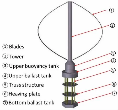
Fig.1 The floating VAWT
1 The parameters of the floating VAWT
The floating VAWT is conceptually designed as shown in Fig.1. The blades drive the tower to rotate, the mechanical energy is converted into electrical energy by the drive mechanism, and the generating device is located in the upper tank of the floating foundation. The wind turbine is a Darrieus-type VAWT, and the main technical parameters are shown in Tab.1[3]. The support foundation is the truss Spar-type floating foundation and the hydrodynamic performance of the floating foundation was studied by Liu et al[12]. The dimensional parameters of the floating foundation are selected as shown in Tab.2.

Tab.1 Parameters of the wind turbine

Tab.2 Parameters of the floating foundation
There are many studies about the Spar-type floating foundation used to support the horizontal axis wind turbine. Karimira et al[13]investigated the influence of wind loads on the motions of the Spar-type floating foundation. Ma et al[14]calculated the dynamic response of the Spar-type wind turbine using the FAST software. Seebai et al[15]analyzed the responses of the Spar platform supporting a 5 MW wind turbine in regular and random waves by experimental and numerical methods. In this paper, the Spar-type floating foundation with heave plates is used to support the VAWT, and the motion performances of the floating VAWT are discussed.
The floating VAWT is moored by three groups and a total of six catenary mooring lines.The angle between each group of mooring line is 120°. The line is designed in the form of chaincable-chain, and they are connected with the floating foundation through the fairleads. The horizontal distance between the anchor and the fairlead is 162 m and the vertical distance is 90 m. The specific parameters of the mooring line are shown in Tab.3.

Tab.3 Parameters of the mooring line

Continue Tab.3
2 The surge-heave-pitch coupling nonlinear motion equations of the floating VAWT
2.1 Establishment of the motion equations
Regarding the whole floating VAWT as a rigid body, considering the inertia force (moment), damping force (moment), restoring force (moment), mooring force, wind and wave loads,the surge-heave-pitch coupled equations of the floating VAWT can be presented as follows,


For the Spar type floating foundation, the nonlinear coupling between the heave and pitch motions is significant. Referring the nonlinear heave-pitch coupling motions equations of the deep sea truss Spar platform[14-15], the restoring matrix can be written as follows:


2.2 Aerodynamic loads and wind pressure
The aerodynamic loads acting on the blades were calculated based on the double-multiple- stream tube theory (Paraschivoiu, 1988). The floating VAWT was dealt as a rigid body,variable interference factors, the dynamic stall (Gormont-Berg model), tower shadow, and Reynolds number variation were considered. The velocities considered the influences of blade rotation, and surge, pitch and heave motions of the floating foundation. The stream tubes were divided into upwind and downwind sectors, the influences of floating foundation motions on the induced velocities of upwind and downwind sectors were considered. Specific derivation process and validation of this model can be found in the work presented by Liu et al[16].
The steady wind pressure and wind heeling moment acting on the tower and the blades(in the parking state) were calculated in accordance with the rules of the API[17], and the formulas are as follows:


The wind pressure is acting on the tower at different heights. By taking the moment about the center of gravity of the floating VAWT, the wind heeling moment acting on the pitch motion of the floating VAWT can be obtained.
2.3 Hydrodynamics and mooring loads
The hydrodynamic calculation is carried out with Sesam/Wadam[18]. This modular is widely used in calculating the hydrodynamics of the offshore structures including the floating foundation. The structure of the floating foundation is divided into the panel model and the Morison model according to the dimensions of the components. The panel model is used to calculate the hydrodynamics of a large-scale structure (upper buoyancy tank, upper ballast tank, heaving plates, and bottom ballast tank) based on the potential flow theory[19].
The fairleads are near the center of gravity of the wind turbine system. The mooring restoring forces acting on the surge and heave of the floating VAWT are considered. The restoring forces of the mooring system are calculated based on the catenary theory[20].
2.4 Damping of the floating foundation
The damping of the floating foundation moved in water is calculated using the CFD method. Liu et al[21]calculated the damping of a truss Spar platform by the CFD method. The same methods are used to calculate the damping of the truss Spar type floating foundation in this paper, including the model establishment and mesh, the free surface tracking and the motion of the structure, etc.
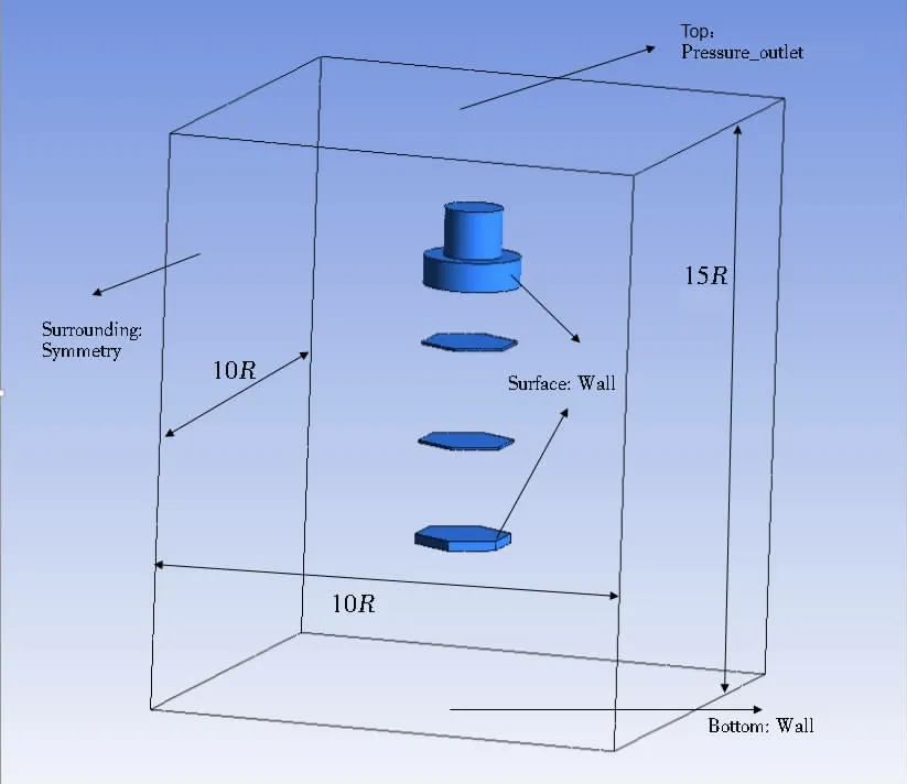
The governing equations are the continuous equations and the Navier-Stokes equation, and to avoid grid quality reduction caused by the large difference in the structure sizes, the truss structures are neglected[21].The incoming and outgoing flow regions of the computational region and the distance from the structure to the left and right walls are all 5 times as much as the maximum radius of the floating foundation. The boundary conditions of the computational region are as follows: the floating foundation surface is set as the wall boundary, the upper part of the tank is set as the pressure outlet boundary, the bottom of the tank is set as the wall boundary, and the surroundings of the tank are set as the symmetrical boundary. The numerical tank model established in the Fluent software is shown in Fig.2.

Fig.2 Numerical tank model
The tetrahedral grids are used to mesh the structure. To improve the calculation accuracy,the size of the grid increases from the structure to the boundaries gradually and the grids are refined around the structure and the free surface. The smallest grids are around the heave plates,and the smallest grid dimensions of 0.2 m and 0.25 m are calculated and compared. It is shown that the calculation results have no obvious difference. Therefore, the smallest grids dimension 0.25 m is selected (around the heave plates), and the total grid number is about one million.The turbulence model is the k-ε model[22], and the free surface is the gas-liquid two-phase flow boundary. The VOF (Volume of Fluid) method is used to track the fluctuation of the free surface where the air is set as the main phase and the water is set as the second phase. The motion of the structures is controlled by using the UDF (the user defined function). The calculations are carried out in the workstation with Intel E5-2687W CPU, 3.4 GHz Turbo, and internal memory with a capacity of 32 GB.
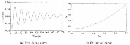
Considering the mass and inertia moment of the upper wind turbine (the wind turbine is in the state of parked), the free decay motions of surge, heave and pitch of the floating VAWT in the calm water are simulated, as shown in Figs.3(a)-5(a).


Fig.3 Free decay curve and extinction curve of surge of the floating VAWT

Fig.4 Free decay curve and extinction curve of heave of the floating VAWT

Fig.5 Free decay curve and extinction curve of pitch of the floating VAWT
The natural periods of surge, heave and pitch are obtained by the average of 7-10 consecutive period cycles of the free decay curves, and the results of natural periods and damping coefficients of the floating VAWT are shown in Tab.4.

Tab.4 Natural periods and damping coefficients of the floating VAWT
Tab.4 shows that natural periods of surge, heave and pitch of the floating VAWT are 46 s,23.5 s and 34.0 s, respectively, and they all avoid the range of 3-18 s within which the main wave energy is concentrated.
3 Results and analysis
3.1 Control strategy
Considering the same directions of winds and waves, Eq.(1) are numerically solved by using the Runge-Kuta method. According to the wind speed, the working goals of the wind turbine can be divided into the following three stages:
(1) When the wind speed is larger than 5 m/s and less than 10 m/s, achieving a higher power coefficient is the goal. The rotation speed of the wind turbine increases until it obtains a higher power coefficient.
(2) When the wind speed is in the range of 10-16 m/s, it is near the rated wind speed and achieving a higher power is the goal. The corresponding rotation rate is adjusted accordingly.
(3) When the wind speed is in the range of 16-25 m/s, to ensure safe operation, the rotation rate of the wind turbine is reduced gradually in order to reduce the aerodynamic loads.
3.2 The response analysis of time histories
Three groups of environmental parameters are considered as shown in Tab.5. Considering the directions of wind and wave are the same, the motion responses of the floating VAWT are calculated and the corresponding power spectrums are obtained by using the FFT (Fast Fourier Transformation) of the time histories. The calculated results are shown in Figs.6-8. The response amplitude, mean values, and frequency characteristics are further analyzed in Tabs.6 and 7.

Tab.5 Calculation parameters

Fig.6 Surge responses of the floating VAWT

Fig.7 Heave responses of the floating VAWT

Fig.8 Pitch responses of the floating VAWT

Tab.6 Analysis of the calculated results

Tab.7 Frequency components (rad/s)
Tab.6 shows that the motion amplitudes of surge, heave and pitch of the wind turbine are small. For the extreme wind speed (case 3), the amplitudes are 5.56 m, 0.29 m, and 1.33 degrees for surge, heave and pitch, respectively. The floating VAWT bears large wind loads as the wind wheel is very high and the mean values of surge and pitch motions are relatively large for the case of cut-out wind speed (case 2), the mean value of the pitch motion is 11.61 degrees and that of the surge is 7.75 m. In the actual design, the diameter of the main hull of the floating foundation and the mooring stiffness can be further increased to reduce the mean values of pitch and surge of the floating VAWT.
The frequency characteristics of the responses of the floating VAWT are different under the three cases. In case 1, the surge frequencies are dominated by the wave frequency (1.26 rad/s). The component of the aerodynamic load frequency (1.15 rad/s) is also included, but the value is small as shown in Fig.6(b). The heave frequency equals the wave frequency; the pitch frequency equals the aerodynamic load frequency. In case 2, the response frequencies of surge,heave and pitch all contain the wave frequency (0.63 rad/s) and the aerodynamic load frequency (0.86 rad/s), where the response frequencies of surge and heave are dominated by the wave frequency, and the pitch frequency is dominated by the aerodynamic load frequency. In case 3, the aerodynamic load is not considered, and the response frequencies of the three degrees of freedom all equal to the wave frequency (0.48 rad/s).
4 Conclusions
The motion responses of a 5 MW floating VAWT are studied considering the wind and wave loads. The viscous damping of the floater is calculated by the CFD method. The nonlinear coupling motion equations of surge, heave and pitch of the floating VAWT are established and the motion responses are analyzed. The conclusions are as follows:
(1) The natural periods of surge, heave and pitch of the floating VAWT are 46 s, 23.5 s,and 34.5 s, respectively, and all avoid the range of 3-18 s where the main wave energy concentrates.
(2) In cases 1 and 2, the response frequencies of the pitch of the floating VAWT are dominated by the aerodynamic load frequency; the response frequencies of surge are dominated by the wave load frequency and a little component of the aerodynamic load frequency is included; the heave frequencies are dominated by the wave frequency. Therefore, aerodynamic load significantly affects the pitch of this floating VAWT.
(3) The response amplitudes of surge, heave and pitch of the floating wind turbine are small for the three typical cases. The mean values of the surge and pitch responses of the floating VAWT are relatively large for case 2 as the height of the wind wheel is very high and the large chord of the blades. In the actual design, the diameter of the floating foundation and the mooring stiffness can be further increased to reduce mean values of pitch and surge of the floating VAWT, and the chord of the blades can be further optimized.
Acknowledgments
This project is supported by the Natural Science Foundation of China under Grant No.51579176, the Natural Science Foundation of Tianjin (No.16JCYBJC21200), and the Fund of the State Key Laboratory of Ocean Engineering, Shanghai Jiao Tong University (No.1501).
杂志排行
船舶力学的其它文章
- Numerical Simulation of Flow-induced Noise of Two Circular Cylinders in Tandem and Side-by-side Arrangements Using a Viscous/ Acoustic Splitting Method
- Transient Pipe Tension Influence on Dynamic Positioning Control During S-Lay Installation
- Dynamic Response of Shipbuilding Sandwich Plate System Subjected to Impulsive Loading
- A Phase Modification Methodology in Modelling Deterministic Freak Wave Train
- Improved Moving Particle Semi-implicit Method with Large Eddy Simulation for Determining Water-entry Impact and Damage to Flat-bottomed Structures
- Numerical Simulation of Cavity and Hydrodynamic Force of the Sphere Water Entry in Consideration of Surface Wettability
