Simulation of Heat Transfer Characteristics in Channel with Square Rib Under Uniform and Turbulent Inlet Conditions
2019-12-03LIHengYUTingWANGDuoZUYingqingXUHongyi
LI Heng,YU Ting,WANG Duo,ZU Yingqing,XU Hongyi
Department of Aeronautics and Astronautics,Fudan University,Shanghai 200433,P. R. China
(Received 25 August 2018;revised 17 September 2018;accepted 2 July 2019)
Abstract: The detailed flow structures and closely-related heat transfer characteristics are investigated along the wall of a cooling channel with rib tabulator by computation. Three typical Reynolds numbers defined by the rib height are set at 200,500,1 300,and the Mach numbers is 0.2,respectively. Two inlet boundary conditions,including the uniform and the fully-developed turbulent conditions,are used to study the turbulence effects on the characteristics of heat transfer in the vicinity of rib and wall. Results show that the local Nusselt number increases when the Reynolds number rises from 200 to 1 300. At lower Reynolds number,the turbulent inlet condition generates more tangible heat transfer enhancement. At higher Reynolds number,however,the uniform inlet condition contributes more to the convective heat transfer effects. The paper discovers that the high Nusselt number has a consistent correlation with the positive and negative sign alteration of the shear layer on the wall,which satisfactorily explains the mechanisms of heat transfer enhancement due to the flow.
Key words: convective heat transfer; turbulent inflow condition; rortex method; shear layer
0 Introduction
To improve the heat transfer efficiency in a cooling channel of turbine blade in modern aero-engine,some wall structures,such as protuberances or pin-fins,were popularly used to increase the heat transfer areas in the devices. On the other hand,the fields of velocity and temperature are affected by these structures,making the convective heat transfer more efficient. Therefore,it is important to give the data of the velocity and thermal fields near the wall.
Recently,Fouladi et al.[1]experimentally investigated the flow and convective heat transfer on a flat plate with a square rib at four typical Reynolds numbers. Compared with the smooth plate,heat transfer is significantly enhanced in the ribbed plate.
Several numerical simulations were conducted to obtain more detailed information of rib flows.Heat transfer and flow in a single-rib mounted channel were investigated by Miura et al.[2-3]. All cases used the fully-developed turbulent inlet conditions.They found that,the mean Nusselt number on the ribbed wall was about 1.3 times larger than the one on a smooth wall. Single rib mounted on the wall was concluded as a useful technique for heat-transfer enhancement[2]. Besides,it was found that the fully-developed turbulence in the separated shear layer correlated well with the higher Nusselt number.Therefore, they concluded that the high performance of heat transfer in the ribbed channel was attributed to the mechanisms of the induced strong fluctuation[2]. Besides,riblet surface structures were also investigated[4].
Due to the fact that most of the previous simulations were based on an incompressible model,the paper considers the compressibility of fluids by solving the compressible Navier-Stokes equations,which is more accurate to reflect the density variations in real flows. In fact,the temperature differences are remarkable between the cooling fluid and the hot turbine blade surface,and therefore the density variations of cooling gas are significant near the hot wall even if the Mach number is not very high.Hence,it is more valid to accurately resolve the density and temperature fields with the current density-based compressible algorithm. In addition,the paper also investigated the effects of inlet turbulence on the heat transfer by comparing the uniform and fully-developed turbulent inflows. Particularly,the next generation of vortex identification method[5]is applied to this papaer to analyze the phenomena of vortical flow structures and their effects on the heat transfer. The flow configuration of cooling channel with a rib tabulator is considered and the Navier-Stokes equations are solved in its two dimensional form. Detailed thermal flow fields are investigated and some strongly-coupled flow and heat transfer phenomena are analyzed.
1 Mathematical Model and Governing Equations
The non-dimensionalized Navier-Stokes equations for compressible fluid are written in Cartesian coordinate as

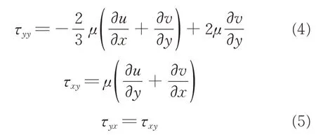
where ρ denotes density. u and v are the velocity components in x and y Cartesian directions,respectively. p and T represent pressure and temperature.μ and k are molecular viscosity coefficient and thermal conductivity,respectively. Etis the total energy defined as ρ( cvT +( u2+ v2)/2 ) ,and Cvis the specific heat at constant volume .
All above parameters are nondimensional variables defined as

where the superscript symbol(')represents a primitive parameter in its dimensional form,and the subscript symbol (∞) denotes dimensional reference variable such as the quantity at inlet. Lrefis the reference length. In the paper,the rib height e is the reference length Lref. The ideal gas equation of state is given by

where R is the specific gas constant,and above equation can be reduce to

where γ is the ratio of specific heat and Ma is the Mach number. The Reynolds number is defined as

The spatial derivatives in convective terms were discretized with the third-order MUSCL scheme[6-7],and the spatial derivatives in viscous term were solved with forth-order centered finite-difference scheme. The third-order TVD Runge-Kutta scheme[8]was used in time advancement. The computational codes are developed based on the above methods.
2 Computational Parameters and Solution Conditions
2. 1 Computational parameters
To study the turbulence effects on the heat-transfer performance,the uniform and fully-developed turbulent inlet conditions are used at three typical Reynolds numbers defined by rib height,Re = 200,500,1 300. As shown in Table 1,the Mach number and Prandtl number are set at 0.2 and 0.71.
The non-dimensional time step Δt is given at 2.0 × 10⁻⁴to satisfy the Courant-Friedrich-Levy(CFL)condition. The turbulence statistics are accumulated up to 1.0 × 10⁶time steps.

Table 1 Computational parameters.
The grid resolutions are measured by Δy+,which is defined as Δy+= Δyuτ/υ,where Δy is the distance of the first point away from the wall,and υ is the kinematic viscosity coefficient. The local friction velocity uτis defined as

where ρwis the fluid density nearest the wall,and τwis the wall shear stress defined as

where μwand ( ∂u/∂y )ware the molecular viscosity coefficient and the normal velocity gradient nearest the wall. The grid resolutions,based on the local friction velocity uτ,meet the condition of a maximum of Δy+<0.5 along the x direction. The local Nusselt number is defined as

where Twis the wall temperature,Tbthe bulk mean temperature, and ∂T/∂n the normal temperature gradient on the wall.
2. 2 Boundary conditions
For the no-slip wall,a ghost-cell immersed boundary method[9-10]is used in the paper with the Dirichlet boundary condition is applied and the fluid velocity on the wall is set equal to zero. On the wall,the normal pressure gradient is zero and then the density can be obtained by the perfect-gas state equation. For the inlet,uniform incoming flow conditions or fully-developed turbulent conditions are applied. For the outlet,the backpressure is set to the environmental pressure and all other variables are based on the zero gradient condition in streamwise direction, namely, the Neumann boundary condition.
2. 3 Computational grid generation
Fig.1 shows the computational domain and the Cartesian coordinate system. The channel dimensions are L = 42e and H = 10e. A square rib with a distance L1= 11e is set at the wall of channel. The temperature at no-slip wall is kept as 1.5 and the incoming flow temperature is 1.0.
The grids are refined towards the channel and rib walls. Such a grid arrangement is used in order to accurately resolve the boundary layers near the walls.

Fig.1 Computational domain and coordinate system
3 Validation and Grid-Dependency Study
3. 1 Model validation
In order to validate present flow model and code,a classical case of the flow over a fixed circular,is studied. The computational domain is 20D ×10D, where D is the cylindrical diameter. The Reynolds number based on D is set at 40 and 1 000.The grid number is 600×600 in x and y directions and the grid resolution is chosen to satisfy Δx ≈Δy ≈1/150D near the cylindrical wall.
Fig.2 shows the cylindrical surface pressure coefficient defined as Cp=( p - p∞)/(1/2ρU2∞).From the comparison,it can be seen that the good agreements are obtained between the present results and the reference data given by Luo,et al.[9]and Ghais,et al.[11].
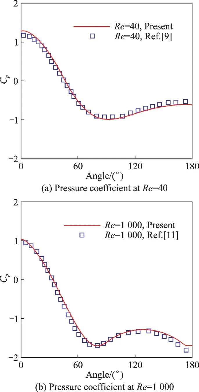
Fig.2 Comparison of pressure coefficient Cp
3. 2 Grid dependence study
The simulations are performed on three levels of coarse,medium and fine grids inydirection,as shown in Table 2. Similarly,the computations are implemented on medium and fine grids inxdirection.

Table 2 Four grid arrangements
Fig. 3 shows that no significant difference is found between the medium and fine grids in x direction. Similarly,there is no significant difference between the medium and fine grids inydirection.Therefore,as a compromise of the grid resolution and computational work,all present studies are conducted on the fine grid in x direction and on the medium grid in y direction.

Fig.3 Comparison of velocityuand temperature T between coarse, medium and fine grids
4 Result Analyses and Discussions
4. 1 Time-averaged characteristics with uniform and fully-developed turbulent inflows
The turbulence fluctuations play a vital role for the downstream flow. Therefore,a fully-developed turbulence in a channel was resolved by a separated Direct Numerical Simulation[12]. The instantaneous turbulence data along a line inside the channel are extracted out and are imposed onto the inlet of the channel with a rib at present cases.
The re-attached point locations are determined based on the average streamwise velocity. For the first-layer grid point nearest the lower wall, the signs of velocity of u are contrary on the both sides of the re-attached point. Therefore,we determine the re-attached point location based on the signs of streamwise velocity.
At lower Reynolds number of Re=200 with the turbulent inlet condition,the Nusselt number increases slowly,and reaches the peak value around the location of 11e.
At lower Reynolds number(Re=200)with the uniform inflow,the phenomena are similar. Compared with turbulent inflow,however,the Nusselt number increases slowly,and the peak is pushed further back to a distance of about 19e location(Fig. 4(a)). Compared with turbulent inflow,the maximum of local Nusselt number is a little smaller with uniform inflow, which is attributed to the smaller temperature gradient near reattached point.As shown in Fig.4(b),the location of Nu/Nu0>1 is near at X=8e for the case with turbulent inlet,while it is near at X=13e for the case with uniform inlet. In Fig.4(b),Nu and Nu0are the local Nusselt numbers on rib-wall and smooth wall. Overall,the turbulent inlet provides more significant heat-transfer effects compared with the uniform inflow.
At medium Reynolds number(Re=500)with the turbulent inlet condition,as shown in Fig.5,the Nusselt number increases rapidly,and reaches its peak at a location around X=8e.Compared with the case of Re=200, the current case has a smaller-sized wake vortices. As the separated region is reduced,the averaged Nusselt number is larger,and the overall heat transfer is more effective than that on the smooth wall. From Fig.5,it can be seen that the present results coincide well with the data from Miura et al.[2-3]. Please note that the equivalent Reynolds number based on rib height is 455 in the computation given by Miura et al.[2-3]. Besides,the reattaching length is similar to the experimental data[3,14],as shown in Table 3.
At medium Reynolds number(Re=500)with the uniform inlet,as shown in Fig. 5,the trend of the Nusselt number is similar to the case with the turbulent inlet. However,the peak is larger and is pushed further back to a location around 10e in Fig.5(a). Besides,compared with turbulent inflow,the maximum of local Nusselt number is larger with uniform inflow,which is attributed to the larger temperature gradient near the reattached point. As shown in Fig. 5(b),the location of Nu/Nu0>1 is near at X=4e for the case with turbulent inlet,while it is near at X=5.5e for the case with uniform inlet. But,the maximum of Nu/Nu0is larger for the case with the uniform inlet. Overall,compared with the turbulent inlets,the uniform inlets provide more significant average heat transfer effects.
At high Reynolds number (Re=1 300) with the turbulent inlet condition(Fig. 6),the Nusselt number increases rapidly, with a local peak at around X=1.5e and then reaches the maximum at around X=5e.
At high Reynolds number (Re=1 300) with the uniform inlet condition(Fig.6),the trend of the Nusselt number is similar to the case with the turbulent inlet condition. However,the peak is larger and the peak location is more forward downstream at around 4.2e location (Fig. 6(a)). Compared with turbulent inflow, the maximum of local Nusselt number is larger with uniform inflow,which is attributed to the larger temperature gradient near the reattached point. As shown in Fig. 6(b),the location of Nu/Nu0>1 is near at X=1.1e for the two case. While,the maximum of Nu/Nu0is larger for the case with the uniform inlet. Overall,compared with the turbulent inlet conditions,the uniform inlet conditions generate the more effective heat transfer effects.
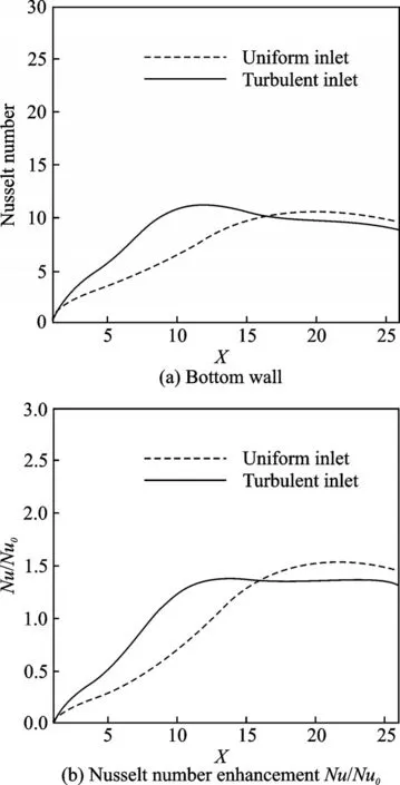
Fig.4 Local Nusselt number of Re=200

Fig.5 Local Nusselt number of Re=500
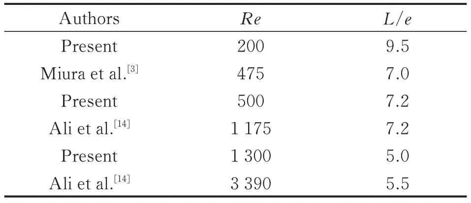
Table 3 Summary of the present reattaching length with the turbulent inlet conditions

Fig.6 Local Nusselt number of Re=1 300
Figs. 7—9 show the mean temperature contours and stream lines at Re=200,500 and 1 300.There is a larger-sized stabilized eddy behind the rib in Fig. 7. However,there are two vortices behind the rib at Re=1 300,including a small and a large one,as shown in Fig.9.
Generally, at low Reynolds number (Re=200),the turbulent inlet provides more significant heat transfer effects. At medium Reynolds number(Re=500) and at higher Reynolds number(Re=1 300),the uniform inlet conditions provide more significant heat transfer effects.

Fig.7 Mean temperature contours and stream lines at Re=200
Generally,with the increase of Reynolds number,the separated region decreases and the reattachment length becomes shorter. This qualitative conclusion can be found in previous data[14]. As shown in Tables 3,4, the reattaching length decreases from 9.5e to 5.0e with the increase of Reynolds number from 200 to 1 300,which coincides well with the experimental data[14]and the numerical results[3].Those phenomena of wake region variation are connected with the convective heat transfer behind rib.With the Reynolds number increases,the wake becomes smaller. As a result,the local Nusselt number peak increases near the reattachment point and the overall heat transfer effects are enhanced. Please note that all the reference data used here are based on the equivalent Reynolds number defined with rib height,and the reattaching length is computed from X=1 to re-attached point location.
4. 2 Structures of instantaneous field
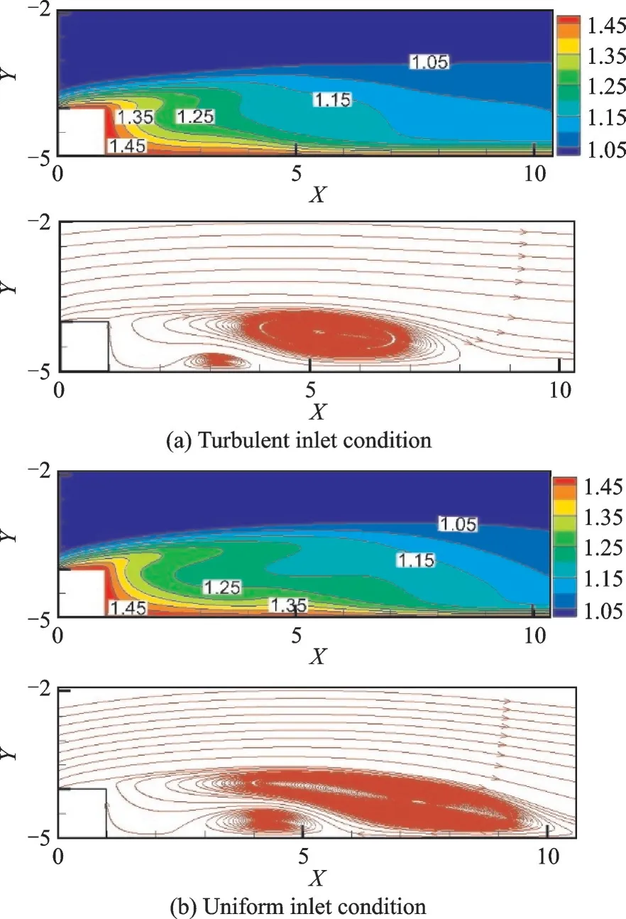
Fig.8 Mean temperature contours and stream lines at Re=500
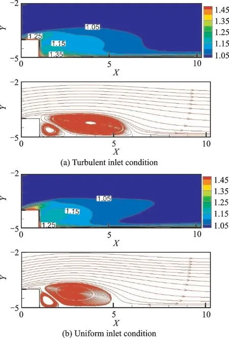
Fig.9 Mean temperature contours and stream lines at Re=1 300
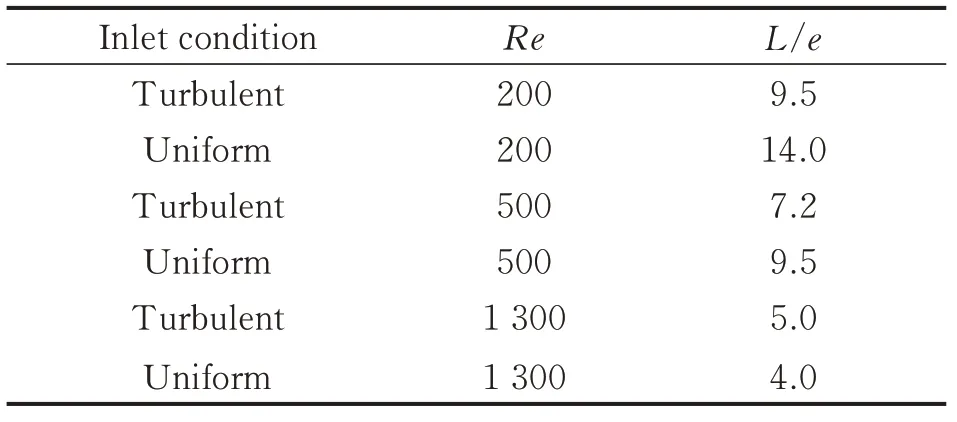
Table 4 Summary of the reattaching length with two inlet conditions
In order to further understand the convective heat transfer,the turbulent structures are analyzed.Traditional methods of the vortice identification,such as vorticity method[15],Q-criterion[16]and λ2-criterion[17],are commonly used. Recently,a novel and more precise approach named as Rortex method was presented by Liu et al.[5,18]. To precisely identify the vortex,the main idea of this method is that,the vorticity vector ∇× v is decomposed into a rotational vector R which is called the Rortex and a non-rotational vector S representing the shear effect

where the rotational vector R is defined as

where r indicates the rotational axes of vortices,and R presents the magnitude of rotational vector.The definitions of R can refer to Liu,et al.[5,18].
In Refs.[5,18],the mathematical definition of Rortex were provided and the validations were conducted based on the late-transition DNS data of semi-flat plate,which well presented the effectiveness of Rortex function in representing the characteristics of vortical flow. Therefore,the paper is based on Rortex to analyze the vortical structures and the its effects on the convective heat transfer on the ribbed wall.
There,the typical cases with the turbulent inlet at Re=500 are illustrated. After the fields are fully developed,the evolutionary process of rotational vector and non-rotational vector are extracted with dimensionless time interval Δt=6, as shown in Fig.10.

Fig.10 Evolution of rortex R and shear S at Re=500 with turbulent inlet condition
The magnitude of Rortex variable R represents the vortex strength,as shown in Figs. 10(a,c,e).As the time evolving,several small-scale vortices are generated on the upper side of rib. With a strong shear near the top surface of rib,those small-scale vortices starte shedding and evolve into the more intensive large-scale eddies,as shown in Fig.10. Particularly,the counter-rotating tail vortices indicated by the red region in Figs. 10(a,c,e)are observed downstream. It is noteworthy that the counter-rotating eddies are generated, strengthened and then gradually weakened,eventually disappeared downstream.
Besides,the prominent strong shear along the upper edge of the separated region and along the channel wall are observed in Figs.10(b,d,f). From a time-sequential frame of the shear variableS,it can be seen that the distinctive positive and negative shear regions alternate when evolving downstream along the wall. Specifically,after a distance of 3e behind the rib,the strong shear banded regions are alternatively changed,which well explains the phenomenon of strong heat transfer effects.
Several cases are extracted to find out the correlation between the high heat transfer characteristics and the alternation of positive and negative shear regions. The shear S is extracted in the case of Re=200 with turbulent inlet condition. As shown in Fig.11,there are alternations of positive and negative shear regions after the location of X=8. Similarly,at higher Reynolds number of Re=1 300 with turbulent inlet condition,the shear S is shown in Fig. 12. It is obvious that the positive and negative shear regions alternate after the rib,especially for the region of 1<X<10,where the Nusselts number is larger(as shown in Fig.6).
Another case of Re=500 with uniform inlet condition is extracted to further confirm the conclusion that the high heat transfer characteristics are relevant with the alternations of positive and negative shear regions. As shown in Fig.13,for the region of 7<X<15 where Nu number is larger(as shown in Fig.5),the positive and negative shear regions alternate. Therefore,it is reasonable to conclude that the alternate regions of the positive and negative shear layer on the wall are consistent with the locations of high Nusselt number.

Fig.11 Evolution of shear S at Re=200 with turbulent inlet condition
5 Conclusions
The paper investigates the convective heat transfer on the channel wall attached with a square-shape rib by resolving the two-dimensional Navier-Stokes equations. Two types of inlet boundary conditions,including the uniform and the fully-developed turbulent conditions, are applied to study the turbulence effects on the characteristics of heat transfer in the vicinity of rib and wall. The study is conducted at three typical Reynolds numbers of Re=200,500,1 300,respectively. Some important conclusions are summarized in the following:
(1)With the increase of Re from 200 to 1 300,the local Nu increases and the overall heat transfer effects are enhanced. Compared with smooth wall,the ratios Nu/Nu0are also increased with the increase of Re.
(2) At lower Reynolds number (Re=200),the turbulent inlet conditions give more effective heat transfer results than the uniform inlet conditions. The turbulent inlet boundary conditions provide stronger disturbance. The separated regions are smaller than the case of the uniform inlet. Accordingly,the local Nu peak positions are advanced,and the overall heat transfer effects are enhanced.

Fig.12 Evolution of shear S at Re=1 300 with turbulent inlet condition

Fig.13 Evolution of shear S at Re=500 with uniform inlet condition
(3)At higher Reynolds number(Re=1 300),the uniform inlet conditions give more effective heat transfer results than the turbulent inlet conditions.Smaller wake eddy regions are observed. In the uniform inlet conditions, the local Nusselt number peak value is larger and the overall heat transfer effects are better than those in the case with turbulent inlet conditions.
(4)Based on the instantaneous field of vortices evolvement,vortices appear near the top surface of the rib with strong shear effects. Then the vortices shed and their intensities increase downstream. Particularly,the alternate regions of the positive and negative shear layer on the wall are consistent with the locations of high Nusselt number.
杂志排行
Transactions of Nanjing University of Aeronautics and Astronautics的其它文章
- Thrust Characteristics Analysis of Long Primary Double Sided Linear Induction Machine with Plate and Novel Shuttle Secondary Structure
- A Nonlinear Control Strategy for Vienna Rectifier Under Unbalanced Input Voltage
- Interleaved-Connected Split Planar Resonant Inductor Design in 1 kV SiC LLC Converters
- A Modified Cohesive Zone Model for Simulation of Delamination Behavior in Laminated Composites
- Effect of Particle Size Distribution on Radiative Heat Transfer in High-Temperature Homogeneous Gas-Particle Mixtures
- Analysis and Calibration of Internal Flow Force of Ejector-Powered Engine Simulator System in Wind Tunnels
